to two widely different distributed systems: the Cooperative File System [1], and ...... and J. Stein, âClass modification in the GemStone object-oriented dbms,â in.
Simplifying Distributed Application Upgrades with Simultaneous Execution Mukesh Agrawal Suman Nath Srinivasan Seshan November 2005 CMU-CS-05-190
School of Computer Science Carnegie Mellon University Pittsburgh, PA 15213
Abstract Developers and operators of distributed systems today face a difficult choice. To provide for the evolution of their systems, they can either require that the software running on all nodes be interoperable, or they can shut down the entire system when an upgrade is required. Requiring interoperability complicates the life of system developers, while shutting down the system annoys users. We propose simultaneous execution, a middle ground between these approaches: an upgrade methodology that reduces the extent of support required for interoperability, while also providing system availability during upgrades. We demonstrate the benefits of our approach by applying it to two widely different distributed systems: the Cooperative File System [1], and I RIS L OG [2]. Our proposal enables easy upgrade of these systems while maintaining system availability, and requiring only minimal support for interoperability.
This work was supported by the Army Research Office under grant number DAAD19-02-1-0389.
Keywords: Distributed systems, upgrades
1 Introduction Many networking researchers have bemoaned that the difficulty of upgrading the Internet infrastructure has lead to the ossification of both Internet research and Internet functionality [3]. Several promising technologies, such as IP Multicast, IntServ, DiffServ, RED, and Fair Queuing, have all failed to be widely deployed at least partly due to the difficulty of changing or upgrading router functionality. Recently, researchers have proposed a number of new application-layer infrastructures for distributed applications [4, 5], distributed storage [1, 6, 7], and sensor systems [2]. However, these infrastructures may share the Internet’s weakness since few (if any) of these infrastructures accommodate easy upgrades. In this paper, we present techniques that simplify the upgrade of many distributed applications, including these critical application-layer infrastructures. With respect to upgradability, the fundamental design choice faced by developers of distributed applications is whether to require versions to inter-operate directly, or to require that the application be shut down as part of the upgrade process. However, we believe that a better alternative is available for many cases: one that maintains system availability, while minimizing the support required for interoperability. In our simultaneous execution approach, we execute multiple versions of an application simultaneously, on the same hardware. We then treat these different versions as separate deployments. Two versions of an overlay network service, for example, are treated as separate overlay networks. To enable multiple application versions to run on the same physical infrastructure, we must prevent interference between multiple versions on a single node, and carefully manage communication between nodes. We prevent interference within a node through the use of virtual machines (VMs). With respect to inter-node communication, we isolate versions, so that only nodes of the same version communicate with each other. We manage messages between clients and the application using application proxies, which mediate client access to the service, masking the existence of two versions. In this paper, we argue for the general applicability of our approach, by describing how a prototype implementation of our design, called the Version Manager, supports two recently proposed distributed infrastructures that differ substantially in their designs: the CFS distributed storage system [1] and the I RIS L OG distributed infrastructure monitoring system [8]. As an example of their differences, CFS relies on an underlying DHT to organize and store write-once data, whereas I RIS L OG uses an underlying tree-based structure to store read-write sensor data. Our experimental results with this prototype show that with our parallel execution approach, we are able to upgrade both applications without disrupting availability. The Version Manager dramatically reduces, but does not eliminate interoperability requirements. The specific components that Version Manager requires are the application proxy, and a tool to copy state from one version to another. Using a proxy framework which we provide, along with existing CFS library routines, the application proxy for CFS is about 500 lines of C++ code. The state copying tool is another 500 lines of C++. For I RIS L OG, the application proxy and state copying tool require 300 lines of C++, and 50 lines of scripts (bash and perl) respectively. In addition to simplifying the complexity of upgrades and eliminating downtime, the Version Manager is also able to propagate new versions of software relatively quickly. For example, with 1
Figure 1: Targeted Application Architecture
a 48 MB software update, Version Manager upgrades a 12 node I RIS L OG system in 7-8 minutes. With CFS, and a 6 MB software update, Version Manager completes an upgrade of 48 nodes in under 6 minutes. The primary cost of using our system is the additional overhead from the virtual execution environment, and from inter-positioning on inter-node communication. During normal execution, when only a single version is running, CFS and I RIS L OG incur overheads of up to 300% and 14% respectively. The overhead for CFS is, admittedly, large. However, we believe this overhead can be reduced through optimizations or architectural changes to the implementation, as we discuss in Section 7. The remainder of this paper is structured as follows: we explain the obstacles to distributed application upgrades in Section 2. In Section 3, we present the design and implementation of our system. In Section 4, we describe our experience in applying our methodology to two existing applications. Section 5 presents experimental results about the performance of our system. Section 6 presents related work, and Section 7 discusses the benefits of our system, and possibilities for performance improvements.
2 Upgrade Obstacles We consider distributed applications with the architecture depicted in Figure 1. Such applications consist of a number of servers, possibly widely distributed, which cooperate to implement a service. Clients utilize the provided service, but do not concern themselves with the server-to-server interactions. Upgrading such applications is difficult due to the numerous hurdles that developers and operators of such systems must overcome. The most significant of these are: designing and implementing inter-operable software; testing upgrades before deployment; planning for recovery, in case the 2
upgrade fails; and deploying the new software. Interoperability The state of the art presents a stark choice for distributed application developers and operators. Either developers must design and implement mechanisms for interoperability, or the operators must shut down the system completely when upgrades need to be made. Given only these options, new software is generally designed to inter-operate with old software, which is replaced in-situ. However, this approach to system evolution suffers from two significant problems. First, it severely constrains the nature of feasible changes. Second, it imposes a heavy implementation and maintenance burden on software developers. With respect to precluded changes, requiring interoperability prohibits changes to important distributed algorithms such as those that control message routing, load-balancing, and cooperative caching. With regard to the developers’ burden, it may be possible to make small changes without significant difficulty. But for large changes, interoperability may essentially require the developer to implement two very different programs in a single process. Testing and recovery The essence of the testing problem is coverage. While simulation and testbed testing may uncover some problems, it is overly optimistic to expect such testing to anticipate problems that will occur “in the wild.” The recovery problem consists of two parts: replacement of faulty software with a new version, and “undoing” the consequences, such as data corruption, of the buggy software. This paper does not focus on these challenges. However, we briefly discuss how the Version Manager could be used to address these issues in Section 7. Deployment process Conceptually, the deployment process might be quite simple. An operator simply logs on to each machine, downloads the new software, and runs some installation script. For large systems, however, this simple process is complicated by the reality that, at any given time, some nodes will be offline. Furthermore, given recent studies which show that operator error is a significant source of outages in Internet services, it is essential to automate the deployment process [9, 10]. Today, automation is hindered by the complexity of error handling. For example: what should be done if a new version fails to start, after the old version has been overwritten?
3 Design and Implementation The key idea behind our design is simultaneous execution. We borrow and adapt the idea from the deployment of IPv6 (and other protocols) in the Internet. Figure 2 provides a logical view of simultaneous execution. The essence of the technique is to allow multiple versions of an application to run simultaneously on a single server node (without interference), and to route client traffic to the appropriate version or versions. The arrows in the diagram indicate the server-to-server communication, highlighting the fact that inter-server routing need not be consistent in old and new versions. Simultaneous execution addresses the interoperability problem by eliminating the need for servers to inter-operate amongst versions. This enables more radical changes in server to server 3
Figure 2: Logical View of Simultaneous Execution
designs. Simultaneous execution simplifies deployment as well. Because new versions do not interfere with old ones, an automated deployment system can simply kill a failed new version, without needing to provide elaborate recovery mechanisms. Figure 3 illustrates the realization of simultaneous execution in the Version Manager architecture. While simultaneous execution simplifies distributed application upgrades, it does require some application specific components, such as the Application Proxy. Next, we explain the details of our Version Manager implementation, and the demands it makes of distributed application developers. We present case studies that quantify the costs of meeting these demands in Section 4.
3.1 Isolating Versions on a Node via Virtual Machines In order to enable different versions of an application to run on a single physical node, as in Figure 3, we must prevent different versions of the application from interfering with each other. To prevent this interference, a number of well-known isolation techniques, ranging from the use of multiple processes to full-blown hypervisors, might be used. At one extreme, processes provide the least isolation, with the lowest performance impact. At the other, hypervisors provide strong isolation, with a greater performance cost. We believe the more limited isolation techniques such as multiple processes, or chroot() environments are insufficient. The multiple process approach suffers from the inability to readily support applications that are themselves structured as multiple processes. Moreover, neither the use of multiple processes, nor chroot() supports multiple user ids, which might be needed by applications that employ “privilege separation” to protect against malicious users. They also do not permit the multiple versions of an application to listen on the same transport protocol (e.g., TCP or UDP) port. A more promising possibility is to use BSD jail() environments, or Linux vservers, as both of these facilities eliminate the user id and listening port limitations. However, both preclude 4
Figure 3: Version Manager Architecture. Colors designate distinct Virtual Machines.
software upgrades that require new kernels. A new kernel might be desired, for example, due to improvements in filesystem or virtual memory algorithms. To support the broadest set of possible changes, we choose the Xen hypervisor as our isolation environment. The Xen hypervisor runs directly on the hardware, and provides an x86-like interface to which operating system kernels are ported. Under Xen, each kernel is executed in a separate domain, consisting of resources such as memory and (possibly virtualized) disks and network interfaces. The system is partitioned into a root domain, used for managing the system, and a number of user domains, which host applications. Typically, physical devices are managed by the root domain, while user domains see virtual disks and network interfaces. We run each application version in a separate Xen domain, with a private virtual disk (backed by storage in the root domain), and a virtual network interface connected to a counterpart in the root domain. The user domains are configured with unique private IP addresses. They are provided with access to the public network via the network address translation feature of the root domain. This approach isolates the application versions by providing near-complete isolation of namespaces. One remaining resource, however, is not isolated: communication channels used by the application. Specifically, these are the channels used for inter-server, and client-server communication. Our inter-node isolation strategy, implemented by the version router (Section 3.2) and application proxy (Section 3.3), provide isolation for these resources.
3.2 Routing Inter-Server Messages with a Version Router The need to manage inter-server communication arises from the fact that the server-to-server protocols for new versions of an application are likely to use the same TCP or UDP port as prior versions. Thus, when a packet arrives from a remote system for the application’s port, it is not clear to which version of the application the packet ought to be delivered. 5
To resolve this contention for transport-layer ports, we interpose a transparent proxy, which we call a version router, on the communication between an application and its peers on other nodes. To guarantee that application traffic is routed to correct versions at peers, the Version Router prepends a header to each outbound request, identifying the version number of the sender. This header is examined and stripped by the proxy on the peer node, which routes the request to the appropriate application version. To accommodate the fact that the application may also communicate with services that do not use version management (e.g. public web servers, mail servers, etc.), the proxy does not interpose on such services. In order to facilitate this differentiated treatment of managed and unmanaged traffic, we require the application to register the network ports used to implement the application’s protocols. This is accomplished with a simple protocol, similar to portmap. We provide a tool that is run as part of the bootstrap process in the isolation environment, which accepts the application port numbers as a command-line argument, and registers the application with the version router.
3.3 Mediating Client Access through an Application Proxy The role of the application proxy is two-fold. First, if the client protocol has changed, the proxy may need to translate client-to-server and server-to-client messages. Second, the proxy must provide a unified view of the system to clients, masking the existence of multiple versions. The translation of requests and responses will necessarily be application specific. We hope that separating message translation and the implementation of the new server will simplify both. However, we acknowledge that the requirement for translation will discourage changes to the client protocols. The task of making multiple independent systems appear to behave as a single consistent system seems, at first blush, to be quite arduous. To provide this illusion, we must solve three subproblems. First, any data available in the system at the time the upgrade is initiated must remain available to all clients during and after the upgrade, regardless of which version of the system they access. Second, any changes made to the client-visible state must be made to all versions. Third, despite the fact that state may be changing even during the upgrade, clients of the old and new versions should be able to agree on what the system state is. As daunting as all this seems, for the applications we have studied, we have accomplished these tasks using very simple approaches. To provide access to old data in new versions, we have written migrators that copy data from old versions to new1 . To ensure that clients of new versions can access this data before migration is complete, we have the application proxy resubmit failed reads to older versions. To guarantee that all changes are visible in all versions, the application proxy submits writes to all versions, returning success to the client if (and only if) all running versions return success. To provide meaningful semantics across clients accessing different versions, we exploit the self-certifying nature of the results returned by the applications. We discuss the implementation costs of these solutions in Section 4. 1
These are run from the upgrade script described in Section 3.5.
6
typedef int (*data_cb_t) (vers_t, databuf&, conn_handler&); struct proxy_callbacks { data_cb_t handle_request; data_cb_t handle_reply; }; Figure 4: Framework/application Interface
3.4 Supporting Application Developers with a Proxy Framework Developing an application proxy is a non-trivial task, particularly for stream protocols (such as TCP) that do not preserve message framing. To assist the developer, we provide a proxy framework in C++, which manages network communications and data buffering, calling into application specific code for message translation and dispatch. Specifically, the framework manages each client connection, and its associated server connections, using a connection handler. The connection handler interfaces with the application specific code via two callbacks: handle_request(), and handle_reply(). The former is called when a message is received from a client connection, the latter is invoked on receipt of data from a server connection. The arguments supplied in these callbacks are the version number of the sender, a buffer containing the data, and a reference to the invoking connection handler. Figure 4 gives the C++ declaration for this callback interface. In addition to the standard read and write operations, databuf supports a peek() operation. This operation returns data from the buffer, without consuming it. Subsequent calls to peek() will return the data following the peeked data. Peeked data is consumed when the handler returns, with the return value of the handler indicating the number of bytes to be consumed. The effects of intermingling read() and peek() calls are undefined. The motivation for peekable buffers is to support parsers that need to examine arbitrary amounts of data before they can determine if the message is complete. Without peekable buffers, the parser would have to support incremental parsing. With peekable buffers, if the message is incomplete, we can simply discard the parser state, and try again when more data is available. Figure 5 details the buffer API. The last argument to the callback is a reference to the connection handler. The connection handler provides calls for enqueuing data either to a server (by specifying the protocol version implemented by the server), or to a client. Ownership of enqueued buffers passes to the connection handler. The connection handler also provides the application code access to a list of running versions. We list the connection handler interface in Figure 6. The version list is required so that the application code can decide where to dispatch a request, and what translation (if any) is necessary (similarly for replies). The versions list provides min(), and max() methods, which return pointers to the least and greatest available server versions. vers_list also provides the usual calls (e.g. operator++(), operator--(), etc.) used 7
class databuf { public: databuf(const databuf& orig); databuf(const databuf& orig, size_t len); int read(char *buffer, int len); int peek(char *buffer, int len); void reset_peek(); void append(char *buffer, int len); }; Figure 5: Buffer API
class conn_handler { public: void enqueue(vers_t version, databuf *buf); void enqueue_client(databuf *buf); vers_list& versions(); }; Figure 6: Connection Handler API
to iterate over lists.
3.5 Upgrade Discovery, Distribution, and Installation As part of the upgrade process, nodes must learn that a new version is available, and they must retrieve the software for the new version. We solve the first problem by using the Version Router to piggyback version advertisement messages on server-to-server communication, and solve the second problem using the BitTorrent file transfer protocol. To support upgrade discovery, the Version Router adds a second field to the header it prepends on outgoing server-to-server messages. Whereas the first field of the header identifies the sending application version, the second field advertises any one of the other versions (randomly selected) running on the same host as the sender. This enables the Version Router on other nodes to learn of new versions from the sender, or to inform the sender that one of its running versions is obsolete. When a receiving Version Router learns of a new version, it executes an upgrade script. The script’s arguments include the address of the Version Router that advertised the new version. The script is responsible for retrieving the new software, and creating a new domain to host the new 8
H(D) public key
directory block
root−block
D .
H(F)
inode block
data block
F .
.
.
..
H(B1)
signature
H(B2)
B1 data block
B2
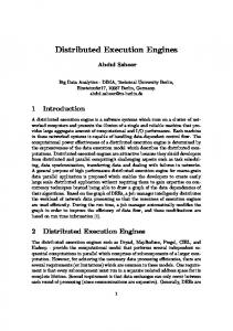
Figure 7: A simple CFS file system structure example. The root-block is identified by a public key and signed by the corresponding private key. The other blocks are identified by cryptographic hashes of their contents. FS DHash Gateway lsd
Chord, finger DHash, merkle−sync
CFS Client
lsd CFS Server
lsd CFS Server
Figure 8: CFS software architecture. Vertical links are local APIs; horizontal links are RPC APIs.
application version. The specific steps taken by the upgrade script are as follows: Download The script copies a .torrent file from the node advertising the new version, and starts a BitTorrent client to transfer the file. Prep FS The script creates a filesystem image for the new application version. Create VM The script creates a Xen domain to host the new version. A boot-time script executed in the new VM manages the remaining tasks: Copy to VM Copies new software from root domain to application domain. Config app Unpack the software and run any installation procedure. Running Run the application.
4 Case Studies In this section, we describe our experience in applying our Version Manager methodology and tools to two applications: CFS and I RIS L OG.
4.1 Cooperative File System (CFS) 4.1.1 Application Overview CFS implements a distributed filesystem over the Chord DHT. Conceptually, when a user writes a file into CFS, the file is broken into blocks 2 . Each block is stored in the DHT, with the hash of the block’s content used as the storage key. The filesystem directory is also stored in the DHT. 2
Physically, blocks are further broken into fragments, which are actually stored on the DHT nodes. The fragmentation of blocks improves fault tolerance [11].
9
Figure 7 illustrates the structure of the CFS filesystem in more detail. All blocks (whether belonging to a file or a directory node) are pointed at via content hashes, with the exception of the root block for a filesystem. A filesystem root is named using a public key from a public/private key pair. The root block is signed using the private key corresponding to the public key under which the root block is stored in the DHT. The use of content-hashes and public-key cryptography provides a self-certifying filesystem. Note that because any modification of a filesystem requires changing meta-data all the way up to the root block, only a holder of the private-key for a filesystem can modify the filesystem’s content. As illustrated in Figure 8, a node participating in CFS typically runs two daemons: the CFS user-space NFS server, and the CFS block server (lsd). Additionally, the node runs an NFS client, to mount the filesystem. The operation of the complete system is as follows: when a process attempts to read a file from CFS, the kernel’s NFS client issues RPCs to the CFS user-space NFS server. The NFS server, in turn, requests blocks from lsd. lsd issues RPCs to its Chord peers, to retrieve the requested block from the DHT. After lsd receives the block, it returns the result to the NFS server, which replies to the NFS client. The kernel then returns the requested data to the reading process. Figure 8 diagrams the protocol interactions between lsd and other entities. From this diagram, we note that lsd communicates with the NFS server using the dhashgateway protocol, which is implemented as RPCs over either a Unix socket or a TCP socket. lsd communicates with its peers using the chord, fingers, dhash, and merkle_sync protocols, typically as RPCs over UDP. The chord and fingers protocols implement Chord routing, while the dhash and merkle_sync protocols provide block insertion/retrieval and block availability maintenance in the face of node join/leave 3 . With this understanding of CFS in hand, we proceed to describe how we apply our methodology to CFS. 4.1.2 Applying Version Manager to CFS For CFS, we choose to provide version management for the protocols implemented by CFS, but not for the NFS protocol, as it is expected to remain stable over different versions of CFS. Below, we describe the tasks required to use Version Manager for CFS. Application Proxy As described earlier, the application developer must provide a proxy which mediates client access during simultaneous execution. Using our proxy framework, and library routines from the CFS source code, we have written a proxy which implements the mediation strategy described in Section 3.3. This proxy is approximately 500 lines of C++ code. State migration To use Version Manager, a developer must also provide a mechanism for copying state from old versions to new. To meet this requirement for CFS, we have implemented a simple program to copy the blocks from one version to another. The program uses the merkle_sync 3 In practice, these protocols are encapsulated in CFS’ transport protocol, which multiplex/demultiplex-es messages between virtual nodes. We omit this detail in further discussion.
10
protocol to query the old version of the application for a list of blocks stored locally. The copy program then attempts to read the same block from the new version. If the read fails, the copier reads the block from the current version, and writes the block to the new version. This program is also about 500 lines of C++ code, making use of the CFS library routines. Consistency As noted in Section 3.3, clients of old and new versions should be able to agree on the system state, even though the state may be changing. Given that clients may be modifying the filesystem at the same time that our state migration tool copies blocks from the old version to the new, it would seem that inconsistencies might arise. Fortunately, CFS already has mechanisms for dealing with write conflicts. Namely, the content of any block written (except a filesystem root block) must hash to the same value as the name (DHT key) under which the block is written. Thus, two writes to the same block with different content are highly unlikely. For root block changes, CFS requires that the root block include a timestamp, and that the timestamp is greater than that of the existing block.
4.2
I RIS L OG
4.2.1 Application Overview I RIS L OG is a distributed network and host monitoring service that allows users to efficiently query the current state of the network and different nodes in an infrastructure. It is built on I RIS N ET [2], a wide area sensing service infrastructure. Currently, I RIS L OG runs on 310 PlanetLab nodes distributed across 150 sites (clusters) spanning five continents and provides distributed query on different node- and slice-statistics4 (e.g., CPU load, per node bandwidth usage, per slice memory usage etc.) of those nodes. At each PlanetLab node, I RIS L OG uses different PlanetLab sensors [12] to collect statistics about the node and stores the data in a local XML database. I RIS L OG organizes the nodes as a logical hierarchy of country (e.g., USA), region (e.g., USA-East), site (e.g., CMU), and node (e.g., cmu-node1). A typical query in I RIS L OG, expressed in the XPATH language, selects data from a set of nodes forming a subtree in the hierarchy. I RIS L OG routes the query to the root of the subtree selected by the query. I RIS N ET, the underlying infrastructure, then processes the query using its generic distributed XML query processing mechanisms. Upon receiving a query, each I RIS N ET node queries its local database, determines which parts of the answer cannot be obtained from the local database, and recursively issues additional sub-queries to gather the missing data. Finally, the data is combined and the aggregate answer is sent to the client. I RIS N ET also uses in-network aggregation and caching to make the query processing more efficient [13]. Both I RIS L OG and I RIS N ET are written using Java. 4
A slice is a horizontal cut of global PlanetLab resources. A slice comprises of a network of virtual machines spanning some set of physical nodes, where each virtual machine (VM) is bound to some set of local per-node resources (e.g., CPU, memory, network, disk).
11
4.2.2 Applying Version Manager to I RIS L OG At a high level, I RIS L OG consists of two independent components: the module that implements the core I RIS L OG protocol, and a third-party local XML database. We choose to provide version management for the first component, since the latter is expected to be stable over different versions of I RIS L OG. In this section, we highlight the changes I RIS L OG requires to incorporate our Version Manager. Application proxy The I RIS L OG application proxy processes queries by submitting them in parallel to all versions, and returning the longest result. The longest result is chosen in order to mask data that is missing from a new version during the interval between the new version being brought online, and the time when all old data has been copied to the new version. Data updates are processed by issuing the update to all versions, and returning success if and when all versions return success. The I RIS L OG application proxy is approximately 300 lines of C++, making use of our proxy framework. State migration I RIS L OG uses a database-centric approach, and hence all its persistent state is stored in its local XML database. Thus, state migration involves transferring the local XML database of the old version to the new version. I RIS L OG provides APIs for an I RIS L OG host to copy or move a portion of the local database to a remote host where it gets merged with the existing local database (used mainly for replication and load-balancing purpose). To copy the latest persistent state from an old version, we start the new version with an empty database and use the I RIS L OG command-line client to copy the whole local database of the old version running on the same host to the new version. The migration tool is implemented with about 50 lines of shell and perl code that calls the command-line client. Consistency Unlike CFS, we do not need to handle the consistency issues for I RIS L OG. This is because I RIS L OG’s data has single writer (the corresponding sensor), and, thus, there are no write conflicts.
5 Performance Evaluation In this section, we examine three key aspects of the performance of our system: • How long does an upgrade take to complete, and how does this scale with the number of nodes in the system? • How much overhead does our system impose during normal execution (i.e., when no upgrade is in progress)? • How much disruption is caused during an upgrade? We first describe our experimental setup, and then answer each question posed. 12
Country
Region
Site
Node
USA−East USA
node1 node2
UIUC
USA−Mid
node1 node2
UTexas
USA−West
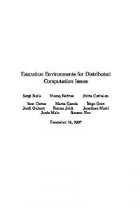
Figure 9: Part of the data hierarchy used in the I RIS L OG evaluation. Subtrees omitted from the diagram are indicated by dashed lines. Root
East
West Mid
CMU
1 Node0
2 Node1
1 Node2
UIUC
UTexas
MIT 2
1
Node3
2 Node5
Node4
1 Node6
Wash
Stanford
2 Node7
1 1 Node8
2 Node9
Node10
2 Node11
Figure 10: Mapping of I RIS L OG data hierarchy to node topology. Bounded regions represent physical nodes containing the data items (shown as smaller solid circles) within the regions.
5.1 Experimental Setup We conducted all our experiments on Emulab [14] using a set of 850 MHz Pentium III machines with 512 MB of RAM, and 100 Mbit Ethernet NICs. The operating system is Fedora Core 2. Our I RIS L OG experiments use a hierarchy of the same depth as the original I RIS L OG running on PlanetLab, but consisting of only a subset of the PlanetLab nodes 5 . Specifically, our hierarchy, part of which is shown in Figure 9, represents three regions (USA-East, USA-Mid, and USA-West) of the USA. Under each region, we have two PlanetLab sites (CMU and MIT in USA-East, Univ. of Texas and UIUC in USA-Mid, Stanford and Univ of Washington in USA-West). Finally, each site has two PlanetLab nodes. We created a topology in Emulab to represent this hierarchy. The latencies of the links in the topology are assigned according to the expected latencies between the of corresponding real PlanetLab nodes. The bandwidth of links between nodes in the same site is 100 Mbps, while that for the wide area links is 5 Mbps. Figure 10 illustrates the mapping of the I RIS L OG data hierarchy to the node topology. 5
Since different nodes at the same level of the hierarchy process a query in parallel, response times mostly depend on the depth of the hierarchy. Therefore, the response times in our simple setup are very similar to those in the original I RIS L OG.
13
Our experiments with CFS focus on a LAN topology of 16 nodes. The links have a bandwidth of 100 Mb/sec, and a delay of