55555 ...
Input.txt
3.3.
deal
java BlackJackSim
java BlackJackSim
java BlackJackSim
java BlackJackSim
faninany
Output.txt
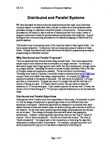
Figure 2. Illustration of a parallelized Blackjack simulation setup. The simulation parameters are read from Input.txt and sent to four BlackJackSim processes. The output from these four processes is combined and written to Output.txt. The DUP Assembly code used to implement the parallel simulation shown in Figure 2 is virtually the same for parallel execution on one host and distributed execution using multiple hosts. The code only differs in the hostnames specified for the various BlackJackSim stages. However, a user running this type of simulation with DUP need not worry about
Optimization
The basic DUP runtime system leaves the developer with the task of selecting a mapping of stages to hosts. This choice is not always obvious, especially for more complex simulations, since resource constraints such as CPU utilization, memory consumption and network bandwidth all need to be considered in order to maximize performance. The Blackjack simulation is primarily limited by the CPU. Using more BlackJackSim stages only gives better performance as long as there are more processors or cores idle on the host. However, even in this simple case, developers might want to confirm that performance is not limited by network bandwidth. Furthermore, in the age of multi-core machines and processor features like hyper-threading [6], it is not always obvious what the optimal number of stages per host is. For the simple Blackjack simulation, it is relatively easy to find the optimal allocation of processes to machines by trying out combinations manually. Figure 3 shows that using the right allocation strategy, the Blackjack simulation scales linearly with the number of available hosts. Naturally, this cannot be expected to be the case in general, especially for more demanding simulations. Section 5. describes a convenient and systematic approach for resource allocation within the DUP
system that makes it easy to perform resource allocation and optimizations for all kinds of DUP applications. 10 9 8
Speedup Multiplier
7 6
API supporting the basic concepts of process and event and two different simulation engines: monolithic and parallel. This support library is implemented in less than 450 lines of actual C++ code and primarily supports the deserialization (parsing), demultiplexing and serializing of events that is required for the parallel simulation. Porting this library to other programming languages could be accomplished in a matter of hours.
5 4
4.1.
3 2 1 0 2
4
6
8
10
12
Number of Hosts
Figure 3. This figure shows the speedup achieved when running our Blackjack simulation on varying numbers of machines (two cores per machine).
4.2. 4. FIDES The approach presented in the previous section is appropriate for situations in which individual simulation runs can be handled by a single computer. However, part of the promise of access to powerful parallel and distributed hardware is to enable “larger” simulations than have previously been possible — this means parallelizing and distributing single simulation runs. Parallel and distributed simulation engines are not new; however, their complexity is a barrier to entry for non-specialists. The goal of FiDES, therefore, is to provide a parallel and distributed Discrete-Event Simulation (DES) framework that can be easily mastered and is straightforward to tune and adapt to different hardware platforms. As with all DES engines, the principle abstractions provided to the developer are process and event. A central goal of FiDES is to provide an architecture that does not require a priori knowledge of how a particular simulation will be decomposed to support parallelism and distribution. To achieve this goal, a simulation written for FiDES can be executed entirely within a single operating system process (of course, this cannot be parallelized or distributed) or it can be executed, using DUP, as multiple operating system processes with one or more simulation processes per program. When executed on a single system, the operating system will schedule the FiDES processes to execute on different cores/processors (thereby leveraging more CPU power). If memory consumption becomes a problem, the configuration can be tweaked to schedule the processes for execution on different machines. We use the term FiDES stage to refer to an operating system process, and simulation process to refer to the DES processes running inside of FiDES stages. For developer convenience, FiDES includes a simple C++
Events
Events consist of a type attribute and a collection of name/value pairs representing other application-specific values associated with the event. For language-independence, names and values are simply strings as far as FiDES is concerned. Of course, developers are free to provide application-specific wrappers to support stronger typing and ease of use in their applications. The C++ API represents events using the (trivial) Event class.
Simulation logic
The simulation logic is expected to process a stream of incoming events, including “advance-time” events, and generate the respective state changes and output events. To facilitate routing of event messages, FiDES requires each simulation process to have a unique identifier that is also specified in events destined for this process. The FiDES C++ API provides a Process class that provides high-level abstractions for writing the simulation logic. Derived classes must implement the processEvent(const Event&) method that is called by the framework when a scheduled event is due to be processed. Derived classes can optionally override the init() method, which is called exactly once by the framework before any events are processed — this is typically used to schedule initial events for the simulation or perform other initialization. Each Process instance maintains its own virtual clock, updated in response to an “advance-time” message from the simulation engine or when the simulation process itself advances time to represent processing or busy time while handling events. Remote and local (self) events are scheduled using one of several convenience variants of the scheduleEvent() method. These methods perform differently depending on the simulation engine being used. Once the application-specific Process classes are defined, they can be instantiated and bound together into a single monolithic FiDES stage using the MonolithicEngine class. This engine is simple to use: (1) an instance of the MonolithicEngine class is created; (2) simulation processes are instantiated and added to the engine instance; and (3) the simulation is executed. The monolithic engine is included to facilitate development
of the application-specific elements of a simulation (i.e., for testing) and to provide simulation developers with a fall-back position in the event that parallel/distributed simulation is not warranted for some simulation scenarios.
4.3.
Parallel Engine
Parallel engine stages are the entities in a distributed FiDES simulation that run the application-specific simulation process logic. Each parallel FiDES stage can be responsible for any number of simulation process instances. A parallel engine must parse event messages, execute the respective processing code and serialize event messages for other FiDES stages. The ParallelEngine class provides a sample implementation of this simple core logic for C++. It is typically used in conjunction with a main function that processes a configuration file specifying which simulation processes should be run by the FiDES stages.
4.4. FiDES Runtime Architecture
Message VTIME VTACK EVENT STATE
Source vtimekeeper ParallelEngine ParallelEngine ParallelEngine
Destination ParallelEngine vtimekeeper ParallelEngine datakeeper
Table 1. Summary of FiDES messages used to communicate between the processes in a parallel simulation execution.
fanin
PE 1 PE 2
...
fanout
Figure 4 depicts a simplified logical organization of a FiDES parallel simulation. In this figure, the grayed boxes represent elements of the FiDES/DUP framework, while the white boxes represent FiDES stages containing simulation processes; lines with arrow-heads represent data flows. Conceptually, the fanin connected to the fanout implements a message bus between all FiDES stages — in practice, the implementation is more sophisticated than this, employing different strategies to filter and otherwise reduce unnecessary data exchange. The white boxes labeled “PE 1”, “PE 2”, etc. represent programs executing the ParallelEngine simulation engine.
a central virtual timekeeper process. While this limits exploitable parallelism, avoiding the need to support rollbacks simplifies the development and integration of simulation components written in many languages by keeping the amount of language-specific support code minimal. The simulation starts when the vtimekeeper simulation process sends a VTIME 0 message (delimited by a newline) to all the FiDES stages. The stages deserialize this message and update the virtual time of all the simulation processes it contains (initializing as necessary). During initialization, some simulation processes may schedule events on other simulation processes — the events are simply serialized by the FiDES stage and passed off to the message bus, where they are handled by the FiDES stage that contains the designated destination process. The vtimekeeper is also notified of the time at which an event is scheduled to occur so it can send a VTIME message appropriately. The vtimekeeper process advances virtual time when all simulation processes have finished processing the previous VTIME message. Simulation processes indicate this by sending a VTACK message. At any time, simulation processes can send a STATE message with a snapshot of relevant elements of their internal state. These messages are handled by the datakeeper processes and typically saved off to files for later analysis.
PE n
vtimekeeper datakeeper Figure 4. Conceptual organization of a FiDES parallel execution. Grayed boxes represent elements of the FiDES infrastructure; white boxes represent application-specific processes. FiDES uses a conservative synchronization strategy with
Table 1 summarizes the major communication messages exchanged between elements of a FiDES parallel simulation. These messages are serialized into a newline-delimited stream of text messages with a simple, easy-to-parse format. Obviously, the flexible design of the parallel execution allows for many configuration options: the developer has to decide on the number FiDES stages and which type(s) to group together within each. The system processes shown in Figure 4 can be located on different machines (in a distributed scenario). As all of these decisions can impact the runtime performance of the simulation, we have developed a suite of tools for analyzing performance, as described in the next section.
5.
DUP OPTIMIZATION AND ANALYSIS
Distributed and parallel systems are, in general, difficult to optimize, and simulation designers without a strong computer
science background can easily be overwhelmed when trying to get simulations to run faster. To make this process easier, we have developed profiling and analysis tools which help determine the performance and interactions of individual system components. We assume an iterative approach, where a user creates a basic distributed pipeline in DUP and then uses the analysis tools to discover the characteristics of each stage and its interactions. This data can then be used to schedule stages for better performance. Our performance analysis tools treat stages as black boxes; they can only observe the behavior of each stage from the point of the operating system. They monitor memory and CPU usage, network bandwidth and data, and system calls (using strace). Additionally, I/O behavior is observed by inserting stages into the data flow graph that monitor data flow between the original stages. The various instrumentations are run independently over multiple profiling runs to minimize interference. We currently do not have any sophisticated support for alignment of traces, other than system times. The DUP profiling infrastructure also creates standalone configurations that are run on data captured by the full system run. This allows profiling of individual components without interference from other system components. This allows a system designer to see best case performance of individual stages and also provides a bound on the theoretical performance of the overall system (by adding the individual stage runtimes together). We provide the ability to record all data transmitted between stages (to be played back offline or directly analyzed). We can also record standard runtime metrics such as CPU usage, memory consumption, system calls, and timing information both on- and offline. Since one of the bottlenecks that may be encountered is network bandwidth and latency, we also record the throughput needed for each stage in the system as well as bandwidth between possible hosts. Since collecting so much data can be overkill, mixing and matching of what is gathered is also supported. To make the collected data more useful to a system designer, the profiling tools can graph this data and merge the plots into a single web page. We will now present two case studies where we use the profiling infrastructure to analyze and improve performance of the Blackjack and FiDES simulations described in the previous sections.
5.1.
Case Study - Blackjack
In order to determine performance bottlenecks of a simulation, we first need to discover the CPU and memory characteristics of each stage. Each stage is first examined in isolation, where interactions between stages do not exist. This gives baseline characteristics of the stages, which can be used to decide what the bottlenecks are for the system. For instance, our blackjack simulations require very little memory (see Ta-
Process deal worker1 worker2 worker3 worker4 worker5 faninany
Mem (MB) 0.33 MB 49.96 MB 49.66 MB 65.15 MB 52.24 MB 50.33 MB 0.39 MB
% Time