Proceedings of IMECE 2005 ASME International Mechanical Engineering Congress and Exposition 2005 November 5-11, 2005, Orlando, USA
IMECE2005-81755
SIMULATING NANOSCALE PROCESSES IN SOLIDS USING DFT AND THE QUASICONTINUUM METHOD
Dan Negrut∗ Mathematics and Computer Science Division Argonne National Laboratory Argonne, Illinois 60439 Email:
[email protected]
Mihai Anitescu Mathematics and Computer Science Division Argonne National Laboratory Argonne, Illinois 60439 Email:
[email protected]
Todd Munson Mathematics and Computer Science Division Argonne National Laboratory Argonne, Illinois 60439 Email:
[email protected]
Peter Zapol Materials Science and Chemistry Divisions Argonne National Laboratory Argonne, Illinois 60439 Email:
[email protected]
PARADIGM OF THE PROPOSED APPROACH Nanostructures have dimensions in the range of 1 ∼ 100 nm and typically contain 102 ∼ 108 atoms. Applying the wellestablished Kohn-Sham DFT method [1] for nonperiodic structures of 60 atoms has led to simulations that can take up to three months to complete. When long range interactions are ignored and pseudo-potentials are used, ab-initio simulations have been carried out for nonmetallic structures with up to 1,500 atoms [2]. The approach that enabled the increase in the number of atoms belongs to the family of so-called O (N) methods [3], which scale as N with the dimension of the problem (in this case the number of electrons). This work is not concerned with fundamental electronic structure computation methods. Acknowledging the smalldimension constraint placed on the problem by the existing Density Functional Theory (DFT)-based methods, the goal of the proposed work is to use techniques that, by closing the spatial scale gap, render electronic structure information at the nanoscale. This electronic structure information is then used to investigate the chemical and mechanical properties of the material. In the context of mechanical analysis of nanostructures,
ABSTRACT A framework is proposed for the investigation of chemical and mechanical properties of nanostructures. The methodology is based on a two-step approach to compute the electronic density distribution in and around a nanostructure, and then the equilibrium configuration of its nuclei. The Electronic Problem embeds interpolation and coupled cross-domain optimization techniques through a process called electronic reconstruction. In the second stage of the solution, the Ionic Problem repositions the nuclei of the nanostructure given the electronic density in the domain. The new ionic configuration is the solution of a nonlinear system based on a first-order optimality condition when minimizing the total energy associated with the nanostructure. The overall goal is a substantial increase in the dimension of the nanostructures that can be simulated by using approaches that include accurate DFT computation. This increase stems from the fact that during the solution of the Electronic Problem expensive DFT calculations are limited to a small number of subdomains. For the Ionic Problem, computational gains result from approximating the position of the nuclei in terms of a reduced number of representative nuclei following the quasicontinuum paradigm.
∗ Address
all correspondence to this author.
1
c 2005 by ASME Copyright °
the methodology proposed follows in the steps of the quasicontinuum work proposed in [4–6]. Specifically, this is an extension of the work in [5, 6], because rather than considering a potential-based interatomic interaction that has a limited range of validity and is difficult to generalize to inhomogeneous materials, the methodology proposed uses ab-initio methods to provide for the particle interaction. At the same time it is a generalization of the method proposed in [4] because rather than considering each mesh discretization element to be part of a periodic and uniformly deformed infinite crystal, the proposed method treats in a generic optimization framework any structure (nonperiodic and inhomogeneous) once the electronic density distribution is available. The electronic structure computation is approached herein as the solution of a constrained minimization problem [7]
min E[ρ, ρA ]
(1a)
ρ(r)dr = Ne
(1b)
ρ
Z
This deformation mapping gives the location r in the global Cartesian reference frame of each point r0 represented in the undeformed material frame. As indicated, the mapping might depend on time t. The variable t does not necessarily represent the time contemporary with the structure under consideration. In fact, in a quasi-state simulation framework, this variable might be an iteration index of an optimization algorithm that solves Eq.(2) in the case ρA is made of nuclear point charges. The components of the deformation gradient are introduced as
FiJ =
∂Φi ∂rJ0
(3)
where upper-case indices refer to the material frame, and lowercase indices to the Cartesian global frame. Thus, F = ∇0 Φ, where ∇0 represents the material gradient operator, and therefore the deformation of an infinitesimal material neighborhood dr0 about a point r0 of D0 is expressed as
where Ne represents the number of electrons present in the system. The solution to this problem depends parametrically on the nuclear density ρA , ρ = ρ(ρA ), a consequence of the BornOppenheimer assumption. Subsequently, the computation of the ground state of the entire system as the solution of the optimization problem
dri = FiJ drJ0
(4)
The concept of small distortion is equivalent to requiring that the spectral radius of F be sufficiently small; that is, min E[ρ(ρA ), ρA ] ρA
(2) ||∇0 Φ||2 < K
From a geometric perspective two assumptions are made in order to close the gap between the subatomic-level representation of the electron density, and the nanoscale scale associated with the structures investigated: (a) there is a near regularity in the atomic compositions of the material, and (b) almost everywhere in the nanostructure the solution to the Ionic Problem results in only small deformations. The assumption (a) is referred to as near-periodicity and is the vehicle that carries first-principles computation results from micro to macro scale. This work does not build on the periodicity assumption, it merely assumes that the material displays close to periodic structure. As explained later, the near-periodicity assumption enables the use of interpolation for electronic structure reconstruction. In regards to the second assumption; i.e., small deformations, in order to formally quantify this concept, the nanostructure is considered to occupy or be contained inside an initial reference configuration D0 ⊂ R3 . The structure undergoes a change of shape described by a deformation mapping Φ(r0 ,t) ∈ R3 .
(5)
is expected to hold for almost everywhere in the domain D0 , for a suitable chosen value of K . As a consequence of the two assumptions introduced, computational savings are anticipated due to a two-tier interpolationbased approach that will reduce the dimension of the problem. First, the electronic structure will be evaluated in some domains by interpolation using adjacent regions in which a DFT-based approach is used to accurately solve the electronic structure problem; this procedure is called electronic density reconstruction (EDR). Second, the position of the nuclei will be expressed in terms of the positions of a reduced set of so-called representative nuclei, repnuclei, in an approach similar to the one proposed in [6]. The proposed approach solves only for the position of these repnuclei; the position of the rest of the nuclei is then obtained by interpolation. 2
c 2005 by ASME Copyright °
{1, . . . , p} → {1, . . . , u} such that Y j = Dχ( j) . Considering that outside D the electron density is zero, the potential generated by the total charge in the system is Z
V (r) = D
ρ(r0 ) + ρA (r0 ) 0 dr ||r − r0 ||
Taking for instance the reference domain Y2 , it is important to consider separately the potential that is generated by electronic density outside this domain, whose complement is denoted by Y¯2 = D −Y2 , that is, for r ∈ D Z
V ext (r;Y2 ) = Y¯2
Figure 1.
ρ(r0 ) + ρA (r0 ) 0 dr + ||r − r0 ||
Z Y2
ρA (r0 ) 0 dr ||r − r0 ||
(6)
Thus, the methodology for external-mode EDR starts by considering the external potential of Eq.(6) for each of the p reference domains Y1 through Yp . NWChem is applied to compute the electronic density in these domains. As far as Y2 is concerned,
NANOSTRUCTURE PARTITIONED IN COMPUTATIONAL
DOMAINS.
Z
THE ELECTRONIC PROBLEM The Electronic Problem refers to the computation of the electron density in a domain surrounding the nanostructure. There are two ways in which this task can be carried out: in external-mode, when third-party software is employed to this end, and internal-mode, when at least in some domain the electron density is computed directly as the solution of Eq.(1). The Electronic Problem is addressed by carrying out high accuracy electronic computation in a select number of domains. In the remaining domains the electron density is recovered by interpolation.
V (r) = V ext (r;Y2 ) + Y2
ρ(r0 ) dr0 ||r − r0 ||
which effectively indicates that the influence of the remaining domains is perceived as the presence of an external potential in which the reference domain Y2 is immersed. This approach however hinges upon the availability of ρ in Y¯2 . In the reference domains Y1 through Yp , ρ is explicitly computed, while based on the near-periodicity assumption, interpolation is used to recover ρ in D −Y . For ρi on domain Di a set of weights ϑ is considered that depends exclusively on the type of interpolation considered (linear, quadratic, etc.). Thus,
External-mode Electron Density Reconstruction Consider, as shown in Fig.1, a two-dimensional structure D = D1 ∪ . . . ∪ D9 that surrounds the nanostructure. The figure presents a two-dimensional case, but the discussion applies both to the two- and the three-dimensional cases. For the externalmode EDR, accurate computation using an established code, such as NWChem [8] for instance, is used to compute ρ in the reference domains Y1 through Yp . The objective is to develop efficient tools that compute the solution to the electronic structure problem up to higher-order terms O (F)2 + O (∇0 F) in the entire domain D = D1 ∪ . . . ∪ Du that contains the nanostructure. This is equivalent to carrying out the first step of the classical homogenization technique (fluctuation reconstruction) [9]. In reference to Fig.1, in what follows, Y = Y1 ∪ . . . ∪ Yp ⊂ D; more precisely, there is an integer-to-integer mapping χ :
0
ρi (Φ(r0 ,t)) =
p
∑
α=1
0
ϑα (i)ρα (Φ(r0 + Tiα ,t))
(7)
where the vector Tiα is the translation vector that based on the 0 periodicity assumption takes the point r0 in domain D0i to its image in the domain Yα . Here, a zero superscript indicates the undeformed domain, and by convention, Greek subscripts are used to index quantities associated with a reconstruction domain Yα , α = 1, . . . , p. Note that in order to define the deformation field, 0 an appropriate representation for Φ(r0 ,t) is necessary. Following the quasicontinuum paradigm [5, 6], this mapping is defined 3
c 2005 by ASME Copyright °
based on the relative displacement of a subset of nuclei in the nanostructure:
0
Φ(r0 ,t) =
0
∑ ϕ(r0 |R0A )Φ(R0A ,t)
introduction of an otherwise involved reconstruction methodology. The Thomas-Fermi-based energy functional assumes the form E [ρ, {RA }] = Ene [ρ, {RA }] + J [ρ] + K [ρ] + T [ρ] +Vnn ({RA })
(8)
A∈B
The deformation needs to be represented only at the points R0A , A ∈ B , and is then reconstructed by interpolation at the other points of the space, by using the shape functions ϕ(·, ·). This aspect of the presentation is going to be covered in more detail when discussing the Ionic Problem. Note that not all domains need to be included in the electronic density reconstruction. If a domain Yγ has a defect, the electronic density is severely distorted away from the nearperiodicity assumption and should not be included in the reconstruction process in neighboring domains. This translates in taking ϑγ (i) = 0 for a domain Di ⊂ D −Y when carrying out interpolation (the density ργ is nevertheless used for reconstructing the external potential V ext (r;Yα ) for each α 6= γ). Concluding on the external-mode EDR, based on an initial electron density distribution, three steps that effectively amount to a nonlinear Gauss-Jacobi method are iteratively taken to reconstruct the electron density in D: (1) for each Yα generate the external potential as in Eq.(6); (2) carry out accurate DFT computation in each domain Yα ; (3) use Eq.(7) to evaluate ρ in D −Y . This iterative process stops when the change in electron density between successive iterations becomes smaller than a threshold value.
where
Z
ZA ρ(r) dr kRA − rk
A=1
J [ρ] =
1 2
Z Z Z
T [ρ] = CF
5
ρ 3 (r) dr
M
4
(11d)
M
ZA ZB kR A − RB k A=1 B=A+1
∑ ∑
3 Here CF = 10 (3π2 )2/3 , and Cx = tation is used:
(11b) (11c)
ρ 3 (r) dr
K [ρ] = −Cx Vnn ({RA }) =
(11a)
ρ(r) ρ(r0 ) dr dr0 kr − r0 k
Z
3 4
¡ 3 ¢1/3 π
(11e)
, and the following no-
Ene - energy corresponding to nucleus-electron interaction J - Coulomb energy K - exchange energy T - kinetic energy Vnn - internuclear interaction energy ZA - atomic number associated with nucleus A ri - global position of electron i R - global position of nucleus of atom A RA (·) without integration limits - an integral over the entire domain.
ZZ
Θ1 (ρ, ρA , r)dr +
Z
M
Ene [ρ, {RA }] = − ∑
Internal-mode Electron Density Reconstruction The discussion for the internal-mode EDR starts with the premise that for a given ionic distribution, the electronic energy is expressed as
E(ρ, ρA ) =
(10)
Θ2 (ρ, ρA , r; ρ, ρA , r0 )dr dr0
The expression of the energy functional of Eq.(10) justifies the notation used in Eq.(9): the kinetic, exchange, and nuclear-electronic energy are represented through the Θ1 term; the electron-electron interaction is associated with the term Θ2 . In the Thomas-Fermi case, the optimization problem of Eq.(1) depends parametrically on the positions of the nuclei:
(9) This representation is commonly used in conjunction with the so-called Orbital-Free DFT (OFDFT) method [10]. Here Θ1,2 are the relevant energy density functionals; ρ is the electronic density; and ρA is the nuclear density, which may include delta functions. The first term typically includes the kinetic energy and an exchange-correlation term, whereas the second integral includes all pairwise interactions. Details regarding the definition of these terms are provided by several authors [11–13]. As an example in this paper the proposed methodology is applied in conjunction with Thomas-Fermi DFT [14, 15]. The Thomas-Fermi functional has well-known severe accuracy limitations. It provides, however, a simple vehicle that allows the
µZ minρ
E(ρ; {RA }) + λ
¶ ρdr − N
(12a)
Z
s.t.
ρdr − N = 0
(12b)
In a domain decomposition framework, it can be shown [16] 4
c 2005 by ASME Copyright °
that solving the above optimization problem in D is equivalent to solving a set of smaller optimization problems on domains Di . For this define Z
Ei [ρi , λi ; ρ¯ i , {RA }] = CF Z
Z
+ Di D−Di
Di
1 ρi (r) ρ¯ i (r0 ) dr dr0 + 0 kr − r k 2 M
−∑
Z
5
ρi3 (r) dr −Cx
Z
A=1D i
Z Z Di Di
Z Di
4
ρi3 (r) dr (13)
ρi (r) ρ¯ i (r0 ) dr dr0 kr − r0 k
Z
0
0
0
ρα (Φ(r0 ,t))K˜ iα (r0 , r0 ) dr0 (16a)
Yα0
0 K˜ iα (r0 , r0 ) =
Di
ZA ρi (r) dr + λi kRA − rk
p ρi (r0 ) 0 dr = ∑ ||r − r0 || α=1
0
ϑα (i) |F(r0 − Tiα ,t)| ||Φ(r0 ,t) − Φ(r0 0 − Tiα ,t)||
(16b)
Define for r0 ∈ Yα0
Z
ρi dr Di
u
0
0
Kαγ (r0 , r0 ) = ∑ K˜ iγ (r0 , r0 )
(17a)
i=1
where ρ¯ i denotes the electronic density in D¯ i , i = 1, . . . , u used as in Eq.(6) to generate the external potential in which the domain Di is considered immersed.
Then, Eq.(15) yields p 2 5 CF ρα3 (Φ(r0 ,t)) + ∑ 3 γ=1
Z
0
0
0
Kαγ (r0 , r0 )ργ (Φ(r0 ,t))dr0 (17b)
Yγ0
M 1 4 ZA − Cx ρα3 (Φ(r0 ,t)) − ∑ +λ = 0 0 0 3 A=1 ||Φ(r ,t) − Φ(RA ,t)||
The nonlinear-system approach. The equivalent optimality conditions for the subdomain optimization problems [16] are
which should hold for any r0 ∈ Yα . Finally, since ρ ≥ 0, a new function η is introduced such that ∇ρi Ei (ρi , λi ; ρ¯ i , {RA }) = 0, λ1 = . . . = λu R ρdr − Ne = 0
i = 1, . . . , u
(14a) (14b) (14c)
ρ(Φ(r0 ,t)) = ηs (r0 ,t)
where s ≥ 4 is an even integer; a recommended value is s = 4, and this will enforce only non-negative values for the density ρ. This new function must then satisfy in the subdomain Yα the following integral equations:
Following the reconstruction paradigm, this accurate computation of the electron density is only going to be carried out in the reference subdomains Y1 through Yp (that is, Dχ(1) through Dχ(p) ). The first order optimality conditions for a generic domain Yα ∈ Y assume the form [16]
u 2 1 5 4 CF ρα3 (r) − Cx ρα3 (r) + ∑ 3 3 i=1
Z Di
(18a)
p 2s s 4 5 CF ηα3 − Cx ηα3 + ∑ 3 3 γ=1
Z
0
0
Kαγ (r0 , r0 )ηsγ (r0 ,t)dr0
0
(18b)
Yγ0
ρi (r0 ) dr0 ||r − r0 ||
M
ZA 0 0 A=1 ||Φ(r ,t) − Φ(RA ,t)||
−∑
(15)
+λ = 0
M
ZA +λ = 0 A=1 ||r − RA ||
−∑
The algorithm at this point calls for the solution of a nonlinear system of integral equations in ρα , α = 1, . . . , p. In order to solve this system, the reconstruction domains Yα are meshed by using hexahedrons. These meshes are denoted in what follows by G1 through G p , and they are associated with Y1 through Yp , respectively.
Next, the density ρi on domain Di is expressed in terms of reconstruction densities ρα ∈ Yα , α ∈ {1, . . . , p} based on Eq.(7). Taking into account the deformation of the structure, 5
c 2005 by ASME Copyright °
quadrature with weights wl :
The direct numerical solution of the nonlinear system of integral equations becomes intractable in Cartesian coordinates because of the singularity when the grid points in a mesh Gα approach a nuclei of location RA (see Eq.(18b)). When approached in spherical coordinates in a three-dimensional representation this apparent singularity is nonexistent [16]. Below, a potentialsmoothing step is introduced to address the situation when r0 → R0A . Compared to the original term ||Φ(r0 ,t) − Φ(R0A ,t)||−1 , the δ-smoothing function
Z
Sδ (r
, R0A ,t) =
δ 1 − e− ||Φ(r0 ,t) − Φ(R0A ,t)||
Z
(19)
0
0
Kαγ (r0 , r0 )ηsγ (r0 ,t)dr0
0
q
0
0
∑
d∈V (τ)
0
ηsγd ϕd (r0l ,t) =
d∈V (τ)
− ∑ ZA Sδ (r
ηsγd ϕld
(20) q
, R0A ,t) + λ
∑
where ϕld are constants that can be precomputed. If one defines 0 for r0 ∈ Yα and r0l ∈ Yγ
kαγd (r0 ) = 0
0
∑ wl Kαγ (r0i , r0l ) ηsγ (r0l ,t)
l=1
ηsγ (r0l ,t) ≈
Yγ0 M
0
Figure 1 shows in the two-dimensional case a mesh cell and the quadrature points. As indicated in this figure, r0i describes the position of the grid nodes; the interior points (quadrature points) 0 0 are located at r0l . The abscissas r0l of the quadrature points are different from the mesh (grid) points, and the value of the unknown function η at these abscissas is obtained by interpolation. 0 Interpolation at point r0l ∈ τ, using a set of shape functions ϕd associated with the nodes d ∈ V (τ), yields
behaves similarly for large values of ||Φ(r0 ,t) − Φ(R0A ,t)|| and δ small but positive, but it converges to 1δ rather than going to infinity when r0 → R0A . Thus, the smoothing process applied to Eq.(18b) leads to
p 2s s 5 4 CF ηα3 − Cx ηα3 + ∑ 3 3 γ=1
0
τ
||Φ(r0 ,t)−Φ(R0A ,t)||
0
0
Kαγ (r0i , r0 ) ηsγ (r0 ,t)dr0 ≈ ||τ||
0
∑ wl ϕld Kαγ (r0 , r0l ) ,
(22a)
l=1
=0
A=1
the discretized form of the integral equation expressed at grid node i ∈ Gα of location r0i ∈ Yα becomes
To make the presentation simpler, the following notation is introduced:
p 2s s 5 4 3 CF ηαi3 − Cx ηαi +∑ 3 3 γ=1
ηβ j – the value of η at the node j of grid Gβ τ– a generic grid discretization cell of volume ||τ|| V (τ) – the set of vertices associated with cell τ (four for a tetrahedron, eight for an hexahedron, etc.) |Gα | – the number of grid points in Gα Yγ0 – undeformed reconstruction domain meshed with Gγ ; Yγ = ∪τ∈Gγ τ
p 2s 5 CF ηαi3 + ∑ ∑ 3 γ=1 τ∈Gγ
Z
∑ ||τ|| ∑
τ∈Gγ
d∈V
(22b)
M
A=1
By denoting the left side of Eq.(22b) by Pαi (η), where η = (η11 , η12 , . . . , η p1 , η p2 , . . .)T , the nonlinear system of equations that should be solved becomes Pαi (η) = 0
0 0 0 Kαγ (r0i , r0 ) ηsγ (r0 ,t)dr0
# kαγd (r0i ) ηsγd
− ∑ ZA Sδ (r0i , R0A ,t) + λ = 0
After discretization, the integral equation above yields at an arbitrary grid node i ∈ Gα of location r0i ∈ Yα ,
"
(23)
for α ∈ {1, 2, . . . , p}, i = 1, . . . , |Gα |. p One additional equation is added to the set of ∑α=1 |Gα | equations above, and it follows from the charge constraint of Eq.(1b). The central idea is again to use the electronic density in the reconstruction domains Yα to express the electronic density in the whole domain D. Skipping the intermediary steps, this yields
(21)
τ
M s 4 3 − Cx ηαi − ∑ ZA Sδ (r0i , R0A ,t) + λ = 0 3 A=1
The integral on τ is performed by q-point Gaussian numerical 6
c 2005 by ASME Copyright °
Z
ρ(r)dr = D
p
∑
then minimized. 0 For α, γ = 1, 2, . . . , p, r0 ∈ Yα0 , r0 ∈ Yγ0 , define
Z
ηsα (r0 ,t)Kˆ α (r0 ,t)dr0
α=1 0 Yα u
Kˆ α (r0 ,t) = ∑ ϑα (i) |F(r0 − Tiα ,t)|
(24a)
(24b)
i=1
For the charge constraint equation, using for the evaluation of the integral on a cell of the undeformed grid Yα0 the same quadrature rule and using the same interpolation method to evaluate the function at the quadrature points yields: p
α=1
ηsαd kˆ αd − Ne = 0
τ∈Yα0 d∈V (τ)
Based on Eq.(7), several of the terms in Eq.(10) become functions of densities in the representative domains: (25a) J(ρ) =
q
kˆ αd =
∑ wl ϕld Kˆα (r0l ,t)
p
Ene (ρ) = −
If a Newton-type method is considered for the solution of the nonlinear system of Eqs.(23) and (25a), the partials are computed as
Z
ρdr =
∑
Z
α=1 0 Yα p Z
∑
α=1 0 Yα
Z Z
0 0 0 J˜αγ (r0 , r0 )ρα (Φ(r0 ,t))ργ (Φ(r0 ,t))dr0 dr0
Yα0 Yγ0
L˜ α (r0 )ρα (Φ(r0 ,t))dr0 ,
M˜ α (r0 )ρα (Φ(r0 ,t))dr0
∑ ||τ|| δατi kααi (r0i ) ηs−1 αi
τ∈Yα0
The difficult part has to do with the kinetic energy and exchange terms T [ρ], K[ρ] whose dependence on the density is not linear and, outside the Thomas-Fermi theory, not even simple to state. Assume that the latter terms are described by a univariate density Θ1 (ρ, r), as indicated by the first term of Eq.(9). For instance, for the Thomas-Fermi representation,
(26a) where δατi = 1 if for τ ∈ Gα , i ∈ V (τ), and δατi = 0 otherwise. When i 6= j or α 6= β, ∂Pαi = ∂ηβ j
1 p p ∑∑ 2 α=1 γ=1
(25b)
l=1
2s−3 s−3 ∂Pαi 10s 4s = CF ηαi3 − Cx ηαi3 + ∂ηαi 9 9
u
i=1
∑∑ ∑
0
|F(r0 − Tiα ,t)| · |F(r0 − T jγ ,t)| ∑ ∑ vα (i)vγ ( j) ||Φ(r0 − Tiα ,t) − Φ(r00 − T jγ ,t)|| i=1 j=1 ¯ ¯ M u ¯F(r0 − Tiα ,t)¯ ˜Lα (r0 ) = ∑ ∑ vα (i) ||Φ(r0 − Tiα ,t) − Φ(R0A ,t)|| A=1 i=1 u ¯ ¯ M˜ α (r0 ) = ∑ vα (i) ¯F(r0 − Tiα ,t)¯ u
0 J˜αγ (r0 , r0 ) =
β
∑ ||τ|| δτ j kαβ j (r0i ) ηs−1 βj
(26b)
τ∈Yβ0
5
4
Θ1 (ρ, r) = CF ρ 3 (r) −Cx ρ 3 (r)
Likewise, p ∂P00 = ∑ ∂ηβ j α=1
∑
τ∈Yα0
α ˆ s ηs−1 αd δτd kαd
which then leads to (26c) p
T [ρ] + K[ρ] ≈
where, by convention, P00 (η) is a notation for the left side of Eq.(25a).
∑
Z
0 α=1 Yα
M˜ α (r0 )Θ1 (ρα , Φ(r0 ,t))dr0
With these approximations and definitions and referring back to Eq.(10), the following electronic structure computation problem is defined:
The Optimizations approach. In this approach the interpolation of Eq.(7) is used to create a reduced energy functional that depends only on the electron density ρα , in the reconstruction domains Yα , α = 1, . . . , p. This reduced energy functional is
Z
min E IO (ρ), 7
subject to
ρ = N,
(27)
c 2005 by ASME Copyright °
where we use the superscript “IO” to denote the “interpolate-andoptimize” approach, and E IO represents the quantity obtained in Eq.(10) after expressing the energy as a function of electron densities in the reconstruction subdomains only. The evaluation of the energy E IO on a grid, and details of the optimization process (gradient computation) is detailed in an upcoming publication [17].
mization problem min f (x1 , T (x1 )) x1
(29)
has the same solution as the previous two, provided that the reduced Hessian is positive definite, which should be true if the original Hessian was positive definite, and the interpolation mapping is full rank. This observation presents the advantage that one solves an optimization problem as opposed to a system of nonlinear equations, with better global convergence safeguards. When there are many local minima, this should help avoid the points that do not have the correct inertia of the Hessian.
Nonlinear equations vs. optimization approaches Recall that optimality conditions followed by interpolation eventually led to the nonlinear system of Eqs.(22b) and (24a). One can be immediately prove that, in aggregate, this system does not represent the first-order conditions of an optimization problem. That issue is a bit unsettling because solving optimization problems is typically a more robust process than is solving equivalent nonlinear equations, since any local minimum of the optimization problem satisfies the nonlinear equation of its optimality conditions. When only a nonlinear system is available, a local minimum of the residual is not necessarily a solution of the nonlinear system. It is therefore important to assess whether there exists an optimization problem that is equivalent, at least up to the leading order of the homogenization error, with the nonlinear system (see [16] for a mode detailed discussion on this topic). In an abstract formulation, we have the following problem:
The case in Eq.(28) corresponds to the internal nonlinearsystem approach, whereas the case in Eq.(29) corresponds to the internal optimization approach. The following result settles in the positive the question of whether the two approaches are equivalent in the limit of the ansatz x2 = T (x1 ) [16]:
Theorem 1. Assume that the solution x∗ = (x1∗ , x2∗ ) of the original optimization problem satisfies kx2∗ − T (x1∗ )k ¿ 1; therefore the multiscale ansatz is not perfect but is merely very good. Then the solution x˜1 of the nonlinear equation and xˆ1 of the reduced optimization problem satisfy
min f (x1 , x2 )
kx1∗ − x˜1 k = O(kx2∗ − T (x1∗ )k2 )
x1 ,x2
where the variables x1 correspond to the representative degrees of freedom, whereas x2 correspond to the rest of the degrees of freedom, and an operator T relates x2 to x1 . Thus, in EDR the representative degrees of freedom are the ones used to parametrize the electron density in the representative domains Yα , α = 1, 2, . . . , p; the mapping T (·) is the interpolation-based operator from (7). Likewise, in the quasicontinuum method [6], the representative degrees of freedom are the positions of the representative nuclei repnuclei; the location of the remaining nuclei, abstractly denoted by x2 , is then obtained as x2 = T (x1 ), where T (x1 ) is the piecewise linear interpolation mapping with nodes at the repnuclei. Based on this observation, one can formulate the nonlinear equation
kx1∗ − xˆ1 k = O(kx2∗ − T (x1∗ )k2 )
NANOSTRUCTURE SHAPE INVESTIGATION The optimization of the geometry of a nanostructure (called hereafter the Ionic Problem), to find the most stable shape reduces to minimizing the total energy given a ground state electronic energy Ee as a function of the position of the nuclei. More precisely, the equilibrium configuration of a nanostructure is provided by that distribution of the nuclei that minimizes the energy Etot = Ee + Enn
(30)
(28)
where Enn is the nucleus-nucleus interaction energy and, central to this development, Ee is the electronic ground-state energy for the considered nuclear distribution.
which will provide the same solution as the original problem. However, the problem is an equilibrium problem with equilibrium constraints rather than a minimization problem. Furthermore, it immediately results using the chain rule that the opti-
Following the Born-Oppenheimer assumption, the electronic energy depends parametrically on the positions of the nuclei through the dependence of the electronic density on the nuclei positions. Thus, in a general form (that has the ThomasFermi of Eq.(10) as a subcase),
∇x1 f (x1 , x2 ), x2 = T (x1 )
8
c 2005 by ASME Copyright °
A couple of remarks are in order. First, the value of the above theorem is that it allows to solve the nuclear equilibrium problem by using only the solution of the electronic density problem, and not the values and the derivatives of the kinetic and exchange energy functionals. Therefore, an entirely nontransparent encapsulation of the electronic structure problem can be used, which allows the proposed approach to work well with legacy codes that do not provide all the needed derivatives. The key observation is that once the electronic density is available, the equilibrium conditions of Eq.(33) can be imposed right away. Whether the electronic structure computation is done with thirdparty software is irrelevant; moreover, there is no need to know the explicit dependence of the energy Ee on the electronic density ρ(r). Second, as suggested in [21], the one-atom conditions of Eq.(32b) can be replaced by cluster conditions, an alternative that will be explored in the future.
Z
ρ(r)Vext (r; {RA }) dr
Ee = T [ρ(r)] + E Har [ρ(r)] + E xc [ρ(r)] +
(31) where T [ρ(r)] is the kinetic energy functional, E Har [ρ(r)] is the electron-electron Coulomb repulsion energy, E xc [ρ(r)] is the exchange and correlation energy, and Vext (r; {RA }) is the ionic potential, which parametrically depends on the distribution of the nuclei {RA }. The explicit dependence of T [ρ(r)] and E xc [ρ(r)] on the density ρ(r) is typically not available, and consequently it is approximated in some fashion [10, 18–20], an issue beyond the scope of this document. According to the Hohenberg-Kohn theorem [7], the electronic density is such that it minimizes Ee subject to the charge conservation constraint of Eq.(1b). The following results is proved in [16]:
When a local quasicontinuum approach is used, the condition of Eq.(33) is imposed only for repnuclei; that is, only for K ∈ B (see Eq.(8)). The position of the rest of the atoms in the system is then expressed in terms of the position of the repnuclei. The repnuclei become the nodes of an atomic mesh, and interpolation is used to recover the position of the remaining nuclei. For instance, if the atomic mesh is denoted by M , τ is an arbitrary cell in this mesh, V (τ) represents the set of the nodes associated with cell τ, and ϕL is the shape function associated with node L, then the condition of Eq.(33) is approximated as
Theorem 2. Consider the optimization problem min Etot = Ee + Enn
(32a)
{RA }
subject to the constraint that for a nuclear configuration {RA } the energy Ee is the electronic ground-state energy, and the electronic density ρˆ that realizes this electronic ground energy additionally satisfies the charge constraint equation of Eq.(1b). Under these assumptions, the first-order optimality conditions for the optimization problem of Eq.(32a) lead to
Z
FK =
∂Eext ∂Enn + =0 ∂RK ∂RK
ˆ ρ(r)
(32b)
∑ RL ϕL (RA ) − RK
r − RK 3
||r − RK || 2
dr +
∑ ∑ ZA
τ∈M A∈τ
L∈V (τ)
3
|| ∑ RL ϕL (RA ) − RK || 2
=0
L∈V (τ)
(34) where FK is interpreted as the force acting on nucleus K, and Z
M
Eext (r; {RA }) = − ∑
ˆ ρ(r)V ext (r; {RA }) dr
A=1 M Z
=−∑
A=1
Enn
This effectively reduces the dimension of the problem from 3 M (the (x, y, z) coordinates of the nuclei), to 3 Mrep , where Mrep is the number of nodes in the atomic mesh (the number of repnuclei). The sum in Eq.(34) is most likely not going to be the simulation bottleneck (solving the electronic problem for ρˆ is significantly more demanding), but fast-multipole methods [22–24] can be considered to speed the summation.
1 M = ∑ 2 A=1
(32c)
ˆ ZA ρ(r) dr |r − RA |
Denoting by Pi , i = 1, . . . , Mrep , the position of the representative nucleus ni , the set of nonlinear equations of Eq.(34) can be grouped into a nonlinear system that is solved for the relaxed configuration of the structure.
M
ZA ZB ∑ RAB B=A+1
(32d)
For each nucleus K in the system, Eq.(32b) leads to the condition Z
ˆ ρ(r)
M
r − RK ||r − RK ||
3 2
dr +
∑
A=1,A6=K
ZA
RA − RK ||RA − RK ||
3 2
=0
f1 (P1 , P2 , . . . PMrep ) = 0 f2 (P1 , P2 , . . . PMrep ) = 0 ··· fMrep (P1 , P2 , . . . PMrep ) = 0
(33) 9
(35)
c 2005 by ASME Copyright °
where fK is the left side of Eq.(34). Finding the solution of this system is done by a Newton-like method. Evaluating the Jacobian information is straightforward but not detailed here. Finally, note that within Eq.(34) a connection is made back to Eq.(8); the position of an arbitrary nucleus A in cell τ is computed based on interpolation using the nodes V (τ), one of many alternatives available (one could consider repnuclei from neighboring cells for instance). Effectively, this provides in Eq.(8) an expression for Φ(·,t) that depends only on A ∈ V (τ) rather than A ∈ B.
PREPROCESSING Partition D in Di (i = 1, , u )
Select reconstruction domains Yα (α = 1,
, p)
Mesh domains Yα (α = 1,
, p)
Provide ραinit in Yα (α = 1,
, p)
Select repnuclei
Initialize deformation mapping Φ to identity
PROPOSED COMPUTATIONAL SETUP Given a nanostructure of known atomic composition (not necessarily mono-atomic or single-crystal), the goal is to determine the electron density distribution as well as the final configuration of the nanostructure, that is, the mapping Φ. Because of the assumption that the kinetic energy of the nuclei is zero, the problem corresponds to a zero Kelvin temperature scenario. A methodology that handles the nonzero temperature case is not addressed here; most likely, it would follow an approach similar to that of Car-Parrinello [25], or Payne et al. [26]. As indicated in Fig.2, the proposed solution has three principal modules: the Preprocessing stage, the Electronic Problem, and the Ionic Problem. Preprocessing is carried out once at the beginning of the simulation. A suitable chosen domain D is selected to include the nanostructure investigated. The partitioning of D into u subdomains Di , i = 1, . . . , u, is done to mirror the underlying periodicity of the structure. A set of subdomains Dχ(1) through Dχ(p) is determined to constitute the reconstruction domains, and as in Fig.1, they are denoted by Y1 through Yp . In these p subdomains explicit electronic structure computation will be carried out accurately. A set of values of the electronic density is required at the nodes of the discretization mesh; the initial guess for the electronic density could be a uniform distribution throughout the nanostructure or, when practical, could be obtained based on a periodic boundary conditions assumption by computing it in a domain D j and then cloning for the remaining domains Dk . Preprocessing concludes with the initialization of the deformation map Φ to be the identity mapping. The Electronic Problem can be solved externally or internally. When it is solved externally, a specialized code such as NWChem [8] is employed to compute the electronic density in the reconstruction subdomains Yα , α ∈ {1, . . . , p}. When the Electronic Problem is solved internally (only for qualitative studies, using for instance the Thomas-Fermi DFT, or OFDFT), the computation requires a mesh grid on which the integrals associated with the formulation are discretized. The algorithm uses three-dimensional interpolation to provide for the density in D j , where j ∈ {1, . . . , u} − {χ(1), . . . , χ(p)}. Independent of the type of solver invoked (external or internal), using a suitable norm the new electronic density ρnew
Interpolate ρ from ρ init
Reconstruct potential based on ρ init Solve system of Integral
Run external DFT code in Yα (α = 1, , p )
Equations for ρ new
ρinit = ρnew
ρ new − ρ init < ε ?
ELECTRONIC PROBLEM
Reposition nuclei based on ρ new
IONIC PROBLEM
Reevaluate deformation mapping Φ
Figure 2.
COMPUTATIONAL FLOW.
is compared to ρinit , and the computation restarts the Electronic Problem after setting ρinit = ρnew , unless the corrected and initial values of the electronic density are close. This iterative process constitutes the first inner loop of the algorithm. The Ionic Problem uses the newly computed electronic density to reposition the nuclei and thus alter the shape of the structure. The nonlinear system of Eq.(35) provides the position of the repnuclei; the other nuclei are positioned based on the quasicontinuum paradigm according to Eq.(32b). The nonlinear system in Eq.(35) is solved by an iterative method, which leads to the second inner loop that in turn has four steps: 1. Evaluate the integral of Eq.(34); when necessary, evaluate its partial with respect to Pi 2. Evaluate the double sum of Eq.(34), which is based on a partitioning of the structure; when necessary, evaluate its partial with respect to the position of the representative atoms 3. Carry out a quasi-Newton step to update the positions Pi of the Mrep representative nuclei. 4. Go back to 1 if not converged 10
c 2005 by ASME Copyright °
Total charge in subdomains
Comparison of two Thomas Fermi implementations 1.04
40
35
Direct Simulation Linear Reconstruction Quadratic Reconstruction
1.02
30 1 25 0.98 20 0.96 15 Direct Simulation Interpolation reconstruction
10
0.94
0.92
5
0 −0.2
0
0.2
0.4
0.6 location
0.8
1
1.2
0.9
1.4
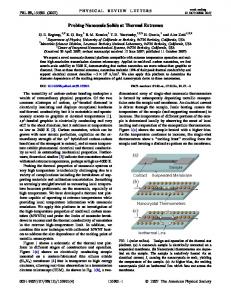
Figure 3. THOMAS-FERMI SOLUTIONS.
1
2
3
Figure 4.
The precision in determining the position of the nuclei is directly influenced by the accuracy of the electronic density ρ(r). Accurately solving the Electronic Problem is computationally intensive, and thus an important issue not addressed by this work is the sensitivity of the solution of the nonlinear system of Eq.(35) with respect to ρ(r). It remains to determine whether a crude approximation of the electronic density suffices for solving the Ionic Problem at a satisfactory level of accuracy. After determining the position of the nuclei, the algorithm computes the new deformation mapping Φ according to Eq.(8). If the overall change in the position of repnuclei at the end of the Ionic Problem is smaller than a threshold value, the computation stops; otherwise the new distribution of the nuclei is the input to a new Electronic Problem (second stage of the algorithm). In summary, the algorithm passes through the Preprocessing stage once. It then solves the Electronic Problem (the first inner loop) and proceeds to the Ionic Problem (the second inner loop). The outer loop (Electronic Problem, followed by Ionic Problem) stops when there is no significant change in the position of the repnuclei.
4
5 6 7 Index of the domain
8
9
10
11
THOMAS-FERMI TOTAL CHARGE.
at the position of the atom and whose length is 1/5 of the distance between two atoms. This results in 11 domains, D1 , D2 , . . ., D11 ; for this example, Y1 = D1 , Y2 = D2 , Y3 = D6 , Y4 = D10 , Y5 = D11 . For discretization of the integral operators the trapezoidal rule was considered. Only the domains D2 , D6 ,D10 are used for interpolation in order to avoid the boundary distortion. Either piecewise linear, or quadratic interpolations is employed for the interpolation-based approach. The parameter δ = 10−4 leads to a slightly different regularization from that described in the previous sections (see Eq.(19)), whereby terms of the type 1/|| · || are replaced with 1/|| · +δ||. The resulting electronic structure optimization problem is solved with the augmented Lagrangian software Lancelot [27], which uses an iterative method to solve the bound constrained subproblem obtained after penalization of the constraints. When using the interpolation method, the interpolation conditions of Eq.(7) are actually enforced as constraints, rather than substituting them in the functional that describes the problem (see E IO of Eq.(27)). When efficiency is a concern, this substitution would be carried out and only the electronic density degrees of freedom in D1 , D2 ,D6 ,D10 ,D11 would be considered. The objective here is only to validate the interpolation-based reconstruction without regard to computational efficiency. The solution of the direct numerical simulation and of the linear-interpolation-based optimization are presented in Fig.3. The results are almost identical, which is an indication that the interpolation approach was effective in reconstructing the solution in the “gap” domains. The results were better yet for the quadratic-interpolation-based reconstruction (not presented in the figure). Note, however, that the solutions are not identical. This can be seen by computing the total charge in the subdomains. The results for the three numerical experiments are pre-
NUMERICAL RESULTS For a simple example, this section compares the numerical results obtained with the direct minimization approach of the Thomas-Fermi DFT, with the ones produced by EDR using the internal optimization approach introduced in this paper. In the one-dimensional test, eleven equally spaced nuclei with unit charge, ZA = 1, are considered; the total number of electrons is Ne = 11. The location of the atoms corresponds to the peaks seen in Fig.(3). A mesh is constructed that has 50 nodes per cell, with 30 of them equally spaced on an interval centered 11
c 2005 by ASME Copyright °
REFERENCES [1] Kohn, W., and Sham, L. J., 1965. “Self-consistent equations including exchange and correlation effects”. Phys. Rev., 140, pp. A1133–A1138. [2] Skylaris, C.-K., Haynes, P. D., Mostofi, A. A., and Payne, M. C., 2005. “Introducing ONETEP: Linear-scaling density functional simulations on parallel computers”. The Journal of Chemical Physics, 122(8), p. 084119. [3] Goedecker, S., and Scuseria, G. E., 2003. “Linear scaling electronic structure methods in chemistry and physics”. Computing in Science and Engineering, 5(4), pp. 14–21. [4] Fago, M., Hayes, R. L., Carter, E. A., and Ortiz, M., 2004. “Density-functional-based local quasicontinuum method: prediction of dislocation nucleation”. Phys. Rev., B70, pp. 100102:1–4. [5] Knap, J., and Ortiz, M., 2001. “An analysis of the quasicontinuum method”. Journal of the Mechanics and Physics of Solids, 49, pp. 1899–1923. [6] Tadmor, E., Ortiz, M., and Phillips, R., 1996. “Quasicontinuum analysis of defects in solids”. Philosophical Magazine A, 73, pp. 1529–1563. [7] Hohenberg, P., and Kohn, W., 1964. “Inhomogenous electron gas”. Phys. Rev., 136, pp. B864–B871. [8] Guest, M. F., Apra, E., Bernholdt, D. E., Harrison, R. J., Kendall, R. A., and Kutteh, R. A., 1996. “High performance computational chemistry: NWchem and fully distributed parallel applications”. In Applied Parallel Computing - Computations in Physics, Chemistry and Engineering Science, J. Dongarra, K. Madsen, and J. Wasniewski, eds. Springer, Berlin,, pp. 278–294. [9] Bensoussan, A., Lions, J.-L., and Papanicolaou, G., 1978. Asymptotic analysis for periodic structures, Vol. 5 of Studies in Mathematics and its Applications. North-Holland Publishing Co., Amsterdam-New York. [10] Wang, L.-W., and Carter, E. A., 2000. “Orbital-free kineticenergy density functional theory”. In Theoretical methods in condensed phase chemistry Progress in Theoretical Chemistry and Physics, S. D. Schwartz, ed. Kluwer, Dordrecht, pp. 117–184. [11] Parr, R. G., and Yang, W., 1994. Density-Functional Theory of Atoms and Molecules. Oxford University Press, Oxford. [12] Jensen, F., 1998. Introduction to Computational Chemistry. John Wiley & Sons Inc., New York. [13] Koch, W., and Holthausen, M. C., 2001. A Chemist’s Guide to Density Functional Theory, second ed. John Wiley & Sons Inc., New York. [14] Thomas, L. H., 1927. “The calculation of atomic fields”. Proc. Camb. Phil. Soc., 23, pp. 542–548. [15] Fermi, E., 1927. “Un metodo statistice per la determinazione di alcune proprieta dell’atomo”. Rend. Accad. Lincei, 6, pp. 602–607. [16] Anitescu, M., Negrut, D., Munson, T., and Zapol, P., 2005.
sented in Fig.3, the right panel. This indicates that the quadratic interpolation method produced a very good fit, with a relative error that is uniformly below 2% for domains 2 through 10. The solution presents some artifacts at the very end of the domain. That in itself is not surprising, given the limitations associated with the Thomas-Fermi DFT.
CONCLUSIONS The paper proposes a theoretical framework for nanostructure investigation. The near-periodicity and small-deformation assumptions introduced are at the center of a methodology that uses interpolation and coupled cross-domain optimization techniques to increase the size of the problems that rely on a DFTbased solution component. In this and the companion work [16], for the electron density computation (the Electronic Problem) formal error bounds are provided for the interpolation and crossdomain reconstruction techniques used. The EDR process can be done internally by following a nonlinear-system approach, or an optimization approach introduced here in conjunction with the Thomas-Fermi DFT; alternatively, it can be carried out externally by using dedicated third-party software such as NWChem. In either case, the EDR methodology calls for the solution of a cross-domain coupled nonlinear problem. The last step of the proposed methodology solves the Ionic Problem; that is, repositioning the nuclei of the structure given the electronic density in the domain. It was shown that the new ionic configuration is the solution of a nonlinear system obtained based on first-order optimality conditions. The Jacobian information for this system is readily available, and its solution does not require the explicit dependency of the kinetic and exchange-correlation energies on the electronic density. The proposed methodology is currently being implemented for three-dimensional structures. The short-term goal is to use the EDR methodology to determine the electronic structure of an inner defect in a silicon crystal. Early simulation results are promising, setting the stage for future tests with more complex structures and more sophisticated DFT approaches.
Acknowledgments This work was supported in part by the Mathematical, Information, and Computational Sciences Division subprogram of the Office of Advanced Scientific Computing Research, Office of Science, U.S. Department of Energy, under Contract W-31-109ENG-38. This work was also supported in part by the U.S. Department of Energy, Office of Basic Energy Sciences-Materials Sciences, under Contract No. W-31-109-ENG-38. We thank Dr. Anter El-Azab of Florida State University and Dr. Anna Vainchtein of the University of Pittsburgh for many useful discussions that helped shape this document. 12
c 2005 by ASME Copyright °
[17]
[18]
[19]
[20]
[21]
[22] [23] [24]
[25]
[26]
[27]
Density functional theory-based nanostructure investigation: Theoretical considerations. Tech. Rep. ANL/MCS– P1252–0505, Argonne National Laboratory, Argonne, Illinois, USA. Negrut, D., Anitescu, M., Munson, T., and Zapol, P., forthcoming. Computational framework for optimization-based dft investigation of nanostructures. Tech. Rep. ANL/MCS– P, Argonne National Laboratory, Argonne, Illinois, USA. Perdew, J. P., and Wang, Y., 1992. “Accurate and simple analytic representation of the electron-gas correlationenergy”. Phys. Rev., B45, p. 13244. Perdew, J. P., and Zunger, A., 1981. “Self-interaction correction to Density Functional approximations for manyelectron systems”. Phys. Rev., B23, pp. 5048–5079. Gunnarsson, O., and Jones, R. O., 1980. “Density functional calculations for atoms, molecules and clusters”. Phys. Scr., 21(3-4). Miller, R. E., and Tadmor, E. B., 2002. “The quasicontinuum method: Overview, applications and current directions”. Journal of Computer-Aided Materials Design, 9, pp. 203–239. Appel, A. W., 1985. “An efficient program for many-body simulation”. J. Sci. Stat. Comput., 6(1), Jan., pp. 85–103. Greengard, L., 1987. The rapid evaluation of potential fields in particle systems. MIT Press. Petersen, H. G., Soelvason, D., Perram, J. W., and Smith, E. R., 1994. “The very fast multipole method”. J. Chem. Phys., 101(10), Nov., pp. 8870–8876. Car, R., and Parrinello, M., 1985. “Unified approach for molecular dynamics and density-functional theory”. Phys. Rev. Lett., 55, p. 2471. Payne, M., Teter, M., Allan, D., Arias, T., and Joannopoulos, J., 1992. “Iterative minimization techniques for ab initio total-energy calculations: molecular dynamics and conjugate gradients”. Rev.Mod.Phys., 64, pp. 1045–1097. Conn, A., Gould, N., and Toint, P., 1992. LANCELOT: A Fortran package for large-scale nonlinear optimization. Springer-Verlag, New York.
13
c 2005 by ASME Copyright °