Results obtained using the four-equation v. 2 âf model (Durbin 1995) are also included for comparison. 3. Results and discussion. The steady two-dimensional ...
Center for Turbulence Research Annual Research Briefs 2001
375
Simulating separated flows using the k-ε model By Svetlana Poroseva
AND
Gianluca Iaccarino
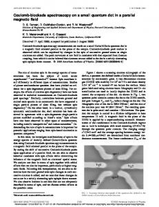
1. Background and motivation Two-equation turbulence models (Jones & Launder 1972; Launder & Sharma 1974) are widely used in industrial CFD applications although their shortcomings are well known. Model limitations have different origins: the performance of the Boussinesq assumption and the choice of the second turbulence scale to build the eddy viscosity have been investigated thoroughly (Cousteix & Aupoix 1997; Apsley & Leschziner 2000). The present paper focuses on the turbulent kinetic energy transport equation and on the modeling parameters in the standard k-ε model based on the linear Boussinesq assumption. The model coefficients in turbulence modeling are usually kept constant in turbulent flows with different geometry and at different Reynolds numbers. Various criteria have been used to define universal values for the constants: the decay of isotropic turbulence is usually considered to fix the value of Cε2 ; the slope of the mean-velocity profile in boundary layers (the Karman constant) determines a relationship between the constants σε , Cµ , Cε1 and Cε2 . The use of these asymptotic constraints on the model constants provides a formally-consistent model. The k-ε model constants have assumed different values depending on the applications. Several investigators (Durbin 1991, 1995; Yakhot and Orszag 1986; Shih et al. 1995) have introduced a variable Cε1 depending on various geometrical and flow parameters (i.e. the strain rate, wall distance, vorticity magnitude, etc.) to introduce the effect of the near-wall anisotropy. Similarly, it was demonstrated by Lumley (1978), Reynolds (1987), Ristorcelli (1995) and Girimaji (2000) that, in turbulence models based on Reynoldsstress transport equations, the coefficients should be functions of flow parameters. In a previous study (Poroseva & B´ezard 2001) it was shown that, after tuning the coefficients, the standard k-ε model was successful in reproducing the measured mean-velocity and shear-stress profiles for several flows (self-similar free shear flows and equilibrium boundary layers in different pressure gradients). According to that study, the coefficients Cµ and Cε2 have the standard values, 0.09 and 1.92 respectively; the relation between coefficients σk and σε is more important for the model accuracy than their absolute values. This is especially important in unbounded flows where turbulent diffusion plays a significant role. A constant ratio σε /σk = 1/0.67 = 1.5 was recommended for practical purposes instead of the standard values, σε = 1.3 and σk = 1. The value of the coefficient Cε1 , has a strong effect on the calculated results; its value depends on the type of flow considered and on the Reynolds number. The rationale behind the choice of the value of the coefficient Cε1 goes back to the formulation of the transport equation for turbulent kinetic energy originally derived assuming homogeneous turbulence. It was shown by Poroseva (2001) that the “rapid” part of the pressure diffusion term can be modeled as an extra production term in the k-equation. The same contribution appears in the ε equation through the coefficient Cε1 . Following the work by Poroseva & B´ezard (2001) a modified k − ε model with tuned coefficients is applied to simulate separated flows in a planar diffuser, over a backstep, in a channel with wavy walls, and in an axisymmetric combustion chamber (Fig. 1).
376
S. Poroseva & G. Iaccarino
2. Turbulence modeling The exact equation for the turbulent kinetic energy in incompressible flows can be derived from the Navier-Stokes equations: Ui − ∂xi ∂xj
∂ui ∂ui ∂2k 1 ∂ ∂p > +ν 2 − < ui u i u j > + < ui > ∂xk ∂xk ∂xj 2 ∂xj ∂xi
(2.1)
where Ui and ui represent the mean and fluctuating velocity components respectively, p is the instantaneous pressure and < − > represents the time average. The terms on the right hand side are the turbulent kinetic energy production (Pk ), the dissipation (ε), the molecular diffusion, the turbulent diffusion and the pressure diffusion. The latter is usually split into “slow” and “rapid” parts; Lumley (1978) showed that the slow part can be modeled as a diffusion process and, therefore, incorporated into the turbulent diffusion term. Poroseva (2001) suggested a model for the “rapid” part of the velocity-pressure gradient correlation < p,j ui >. In the turbulent kinetic energy transport equation, the model contracts (at j = i and summation over indexes) to a model for the “rapid” part of the pressure diffusion. The new proposed form for the k equation is: �� � � � � ∂k ∂k ∂ νt 3 = Pk − ε + (2.2) Ui ν+ + − + Ck Pk , ∂xi ∂xj σk ∂xj 5 where the last term on the right hand side shows the contribution of the “rapid” part of the pressure diffusion. It must be pointed out that this formulation for the “rapid” part of the pressure diffusion is similar to the model derived ad hoc by Demuren et al. (1996) by analyzing DNS data; according to this work the Ck coefficient should vary between 0.6 and 0.9. Equation (2.2) is an extension of the standard k equation but it still does not represents the velocity/pressure-gradient correlation explicitly; the slow contribution is still lumped in with the turbulent diffusion term. The equation for the turbulence dissipation ε closely resembles Eq. (2.2): ∂ε ∂ ε = (Cε1 P − Cε2 ε) + ∂xi k ∂xj Finally the eddy viscosity is defined as : ui
�� � � ∂ε νt ν+ σε ∂xj
k2 ε The standard values of the model coefficients are: νt = Cµ
(2.3)
(2.4)
Cµ = 0.09; Cε1 = 1.44; Cε2 = 1.92; Ck = 0.6; σk = 1; σε = 1.3. The value Ck = 0.6 corresponds to homogeneous turbulence (Poroseva, 2001). This model will be referred to as model LS1. A second set of constants has been used (LS2) Cµ = 0.09; Cε2 = 1.92; σk = 1; σε = 0.67
k-ε for separated flows
x/H=-3
x/H=4 x/H=6
x/H = 12
(a)
x/H = 0.25
377
x/H = 14
x/H = 16
(b)
x/R = 1.68
x/H = 0.75
x/R = 3.6
x/R = 0.7
(c)
(d)
Figure 1. Test problems considered: (a) Backstep; (b) Diffuser; (c) Wavy Channel; (d) Combustion Chamber
The values of Cε1 and Ck have been chosen to fit the experimental data for each test case and will be reported later. Equations (2.2-2.4) represent the high-Reynolds-number form of the k-ε model; the damping function approach proposed by Launder & Sharma (1974) has been used to correct the behavior of turbulent quantities in the viscous dominated near-wall regions. Results obtained using the four-equation v 2 − f model (Durbin 1995) are also included for comparison.
3. Results and discussion The steady two-dimensional Reynolds-averaged Navier-Stokes equations for an incompressible fluid are solved using a commercial CFD code (Fluent v5.3). The first problem selected is the backstep flow (Jovic & Driver 1995), reported in Fig. 1a. The Reynolds number based on the inlet velocity and the step height is 5,100. The flow at the inlet is a fully developed boundary layer. Separation is fixed at the step and the expansion generates a large recirculating region with strong negative velocity and
S. Poroseva & G. Iaccarino 3
3
2
2
y/H
y/H
3
2
y/H
378
1
1
0
0.5
1
0
1
0
u/ui
k/u2i (a)
0.03
0.5
1
u/ui
3
3
2
2
1
0
0
y/H
2
1
0
1
y/H
3
y/H
0.5
u/ui
0
1
0
k/u2i (b)
0.03
0
0
k/u2i
0.03
(c)
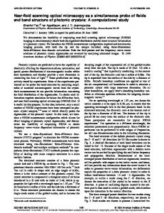
Figure 2. Results for the flow over a backstep: velocity (top) and turbulent kinetic energy : model profiles (bottom). (a) x/H = -3; (b) x/H = 4; (c) x/H = 6. ◦ : experiments; : model LS2; : v 2 − f results. LS1;
high turbulent kinetic energy (measurements are available at several stations downstream the step). The coefficients for the model LS2 are defined as Cε1 = 1.85 and Ck = 0.8. Figure 2 shows results for streamwise velocity and turbulent kinetic energy (scaled by the inlet velocity). All three models predict similar profiles upstream of the step (Fig. 2a). Downstream, the LS1 does not correctly reproduce the separation zone, whereas the LS2 and v 2 − f models are in good agreement with the experimental data (Figs. 2b-2c). In addition, the LS1 fails to predict the correct friction coefficient cf in the recirculating bubble and underestimates cf in the recovery region, whilst the other models produce very similar friction levels (Fig. 3). The second test case is the flow in an asymmetric diffuser (Fig. 1b). The flow is fully developed at the inlet. The Reynolds number based on the bulk velocity and the inlet height is 20,000. The presence of a mild adverse pressure gradient induces separation on a smooth surface, which is very challenging for turbulence models. Mean velocity and turbulent kinetic energy profiles are available as well as skin friction (Buice & Eaton 1997) to identify the extent of the separated region. As in the previous case, the LS1 predictions are in poor agreement with the measurements; on the other hand, the model LS2 (with coefficients Cε1 = 1.5 and Ck = 0.6) is accurate in predicting both the mean velocity and the turbulent kinetic energy (Fig. 4). The LS2 model captures the extent of the separation region very well (Fig. 5). The third case is the flow in a periodic wavy channel (Fig. 1c). The Reynolds number based on the bulk velocity and the average channel height is 11,000. The flow separates on the downhill slope and reattaches uphill; only mean velocity measurements are available
k-ε for separated flows
379
6
cf x 1000
3
0
-3 0
20
40
x/H
Figure 3. Results for the flow over a backstep: skin friction coefficient. ◦ : experiments; : model LS1; : model LS2; : v 2 − f results.
1
1
1
0 0
y/H
y/H
y/H
0
-1 -1 -1
-2
0
-2
0.5
0
u/ui
0.5
0
u/ui
1
0.5
u/ui 1
1
0 0
y/H
y/H
y/H
0
-1 -1 -1
-2
0
2
0.01
-2
0
2
0.01
0
2
k/ui
k/ui
k/ui
(a)
(b)
(c)
0.01
Figure 4. Results for the flow in a diffuser: velocity (top) and turbulent kinetic energy profiles : model LS1; (bottom). (a) x/H = 24; (b) x/H = 28; (c) x/H = 32. ◦ : experiments; : model LS2; : v 2 − f results.
in this case (Kuzan 1986). All the models are reasonably accurate in predicting the velocity profiles. The coefficients used for the LS2 model are Cε1 = 1.5 and Ck = 0.6. The fourth case is an axisymmetric combustion chamber (Fig. 1d). A central pipe stream and an annular swirling stream enter a large cylindrical chamber, and in response to a strong adverse pressure gradient a small recirculating region is created. The Reynolds number based on the pipe bulk velocity and diameter is 75,000. Streamwise and swirl
380
S. Poroseva & G. Iaccarino
cf x 1000
2.0
1.0
0.0
0
50
x/H
Figure 5. Results for the flow in a diffuser: skin friction coefficient. ◦ : experiments; : model LS2; : v 2 − f results. model LS1;
:
0.4
0.5
0.3 0.4
y/H
y/H
0.2 0.3
0.1
0.2 0.0
0.1
0
0.5
u/ui (a)
1
-0.1
0
0.5
1
u/ui (b)
Figure 6. Results for the flow in a wavy channel: axial velocity profiles. (a) x/H = 0.25; (b) x/H = 0.75. ◦ : experiments; : model LS1; : model LS2; : v 2 − f results.
velocities are measured at various stations in the chamber (Hagiwara et al. 1986). The coefficients used in this case are Cε1 = 1.7 and Ck = 0.6. Model LS1 considerably overestimates the extent of the recirculating bubble and the velocity on the chamber axis; models LS2 and v 2 − f , on the other hand, predict the velocity quite accurately (Fig. 7). The swirl velocity is reproduced fairly well by all models.
4. Conclusions and future plans A modified form of the turbulent kinetic energy equation that explicitly accounts for the “rapid” part of the pressure diffusion term (Poroseva, 2001) has been tested for separated flows. The production term in the equation is controlled by an additional coefficient (Ck ) related to the Cε1 coefficient in the ε equation. The choice of the coefficients in the k − ε models is known to be critical for the accuracy of the numerical predictions. The results presented in this work complement the results for free shear flows and equilibrium
k-ε for separated flows
0.3
0
0
1
r/R
1
r/R
r/R
0.6
0.5
0 -0.5
1
0
u/ui
0
1
0.5
1
1
r/R
0.3
0
0
u/ui
1
r/R
r/R
0.5
0.5
u/ui
0.6
0
381
0.5
0
0
0.5
0.5
0
0
0.5
w/ui
u/ui
u/ui
(a)
(b)
(c)
Figure 7. Results for the flow in a combustion chamber: axial (top) and swirl velocity component profiles (bottom). (a) x/R = 0.7; (b) x/R = 1.68; (c) x/R = 3.6. ◦ : experiments; : model LS1; : model LS2; : v 2 − f results.
boundary layers reported by Poroseva & Bezard (2001), and indicate the optimal values for these coefficients for massively-separated flows. It is worth noting that the Ck values found in this study are within the range suggested by Demuren et al. (1996) from the analysis of DNS data of wakes and mixing layers. The proposed form of the turbulent kinetic energy equation is not complete. It reflects only the additional contribution of the rapid part of the pressure diffusion term. In order to derive the complete form of the equation in inhomogeneous turbulence, two more issues must be considered: (i) modeling the “slow” part of the pressure diffusion term in inhomogeneous turbulence, (ii) consistency of the models for the velocity-pressure gradient correlation Πij and the dissipation tensor εij . These issues will be addressed in the future. Several formulations are available in the literature to define the value of Cε1 as function of various flow and geometrical parameters. As an example, in the v 2 − f model (Durbin, 1995) the following function is used: �4 � Cε1 = 1.3 + 0.25/ 1 + (0.15d/D)2 Here d is the distance from the walls and D is a turbulence length scale proportional to k 3/2 /ε. This corresponds to a linear interpolation between a near wall value of 1.55 and a free stream value of 1.3. Other formulations (Shih 1998) use the ratio between production and dissipation of turbulent kinetic energy to achieve the same goal of interpolating between two values of Cε1 . Future work will address the influence of different formulas on the computed results.
382
S. Poroseva & G. Iaccarino REFERENCES
Apsley D. D. & Leschziner, M. A. 2000 Advanced turbulence modeling of separated flow in a diffuser. Flow, Turbulence and Combustion 63, 81-112. Buice, C. U. & Eaton, J. K. 1997 Experimental investigation of flow through an asymmetric plane diffuser. Thermosciences Divn., Dept. of Mech. Engg., Stanford Univ. Report No. TSD-107. Cousteix, J. & Aupoix, B. 1997 Mod`eles de turbulence: principes et applications. In: Proc. 16eme Congres Canadien de M´ecanique Appliqu´e Demuren, A. O., Rogers, M. M., Durbin, P. & Lele, S. K. 1996 On modeling pressure diffusion in non-homogeneous shear flows Proc. 1996 Summer Program, Center for Turbulence Research, NASA Ames/Stanford Univ., 63-74. Durbin, P.A. 1991 Near-wall turbulence closure modelling without damping functions. Theor. Comput. Fluid Dynamics 3, 1-11. Durbin, P. A. 1995 Separated flow computations with the k-ε-v 2 model. AIAA J. 33, 659-664. Girimaji, S. S. 2000 Pressure-strain correlation modelling of complex turbulent flows. J. Fluid Mech. 422, 91-123. Hagiwara, A., Bortz, S., & Weber, R. 1986 Theoretical and experimental studies on isothermal, expanding swirling flows with application to swirl burner design. Results of the NFA 2-1 Investigation. Intl. Flame Res. Foundn. Doc. No F259/a/3/ Jones, W. P. & Launder, B. E. 1972 The prediction of laminarization with a twoequation model of turbulence. Int. J. Heat Mass Transfer 15, 1-32. Jovic, S. & Driver, D. 1995 Reynolds number effect on the skin friction in separated flows behind a backward-facing step. Expts. in Fluids 18, 464-472. Kuzan, J. D. 1986 Velocity measurements for turbulent separated and near-separated flows over solid waves. Ph.D. Thesis, Department of Chemical Engineering, University of Illinois at Urbana. Launder, B. E. & Sharma, B. I. 1974 Application of the energy-dissipation model of turbulence to the calculation of flow near a spinning disc. Letters in Heat and Mass Transfer 1, 131-138. Lumley, J. L. 1978 Computational modeling of turbulent flows, Adv. Appl. Mech. 18, 123-177. Poroseva, S. V. 2001 Modeling the “rapid” part of the velocity-pressure gradient correlation in inhomogeneous turbulence. Annual Research Briefs, Center for Turbulence Research, NASA Ames/Stanford Univ., 367–374 Poroseva, S. V. & Bezard, H. 2001 On ability of standard k-ε model to simulate aerodynamic turbulent flows. CFD Journal 9, 464-470. Reynolds, W. C. 1987 Fundamentals of turbulence for turbulence modeling and simulation. Lecture Notes for Von Karman Institute, AGARD CP-93. Ristorcelli, J. R., Lumley, J. L. & Abid, R. 1995 A rapid-pressure covariance representation consistent with the Taylor-Proudman theorem materially-frame-indifferent in the 2D limit. J. Fluid Mech. 292, 111-152. Shih, T. H., Liou, W. W., Shabbir, A., Yang, Z. & Zhu, J. 1995 A new k-ε eddy viscosity model for high Reynolds number turbulent flows. Computers & Fluids 24, 227-238.
k-ε for separated flows
383
Yakhot, V. & Orzag, S. 1986 Renormalization group analysis of turbulence. J. of Sci. Comput. 1, 1-51.