MA2-5
Proceedings of the 1999 EEE International Symposium on Computer Aided Control System Design Kohala Coast-Island of Hawai'i, Hawai'i, USA August 22-27, 1999
1120
Simulation and Animation in Simulink and VRML Ole Ravn, Thomas Dall Larsen and Nils Andersen Departement of Automation, Technical University of Denmark, Building 326, DK-2800 Lyngby, Denmark, E-Mail:
[email protected] tions, both simple 2D animations and more advanced 3D animations. However much effort has to be invested in the model building and in the non standard integration into the simulation environment. There is a large potential for using animations for better understanding the perlimnancc of' ;I system especially for non control engineers where a simple visualization often will give a more immediate impression than numbers and graphs. Our aim has been to make an easy to use yet powerful and versatilc concept and toolset for integrating 3D animations in a standardized way in a well known simulation environment but with a modest added design effort. Our goal has been not more than ii 10% extra effort compared to the effort of creating thc simulation model. This would make it possiblc to build animation model as a standard part of simulation inodels ciiliaiicing the understandability of their results.
Abstract The puper describes ci solution that enables the control sysand seandessly integrate visualization into sirnulutions studies. The design target has been that no inore than 10 percent oj' the modelling eff,i-t should be devoted to iiiodelling the visunlizution part of the simulution. The visualization niodule (VRML Animation Toolset) in the prototype iiiiplementution is interjuced to Simulink, but the clesign aims ut inaking the concept simulation platform independent. The visuulizcition iiiodule can nlso be connected to real systenis using the Red-Time Woskshop (RTW) thus enahling a visiiul coiirpurison of the simulation system perfi,rmance mid the truc systoin perjonnancc. The paper also c.xplains the undei-luyinp .siinulrition centered ui-chitectirse crntl the links to tho prototype iiiiplenicJtitntion. Kcyworcls: visualization. siiiirilutioti. niotlelling. tem designer to easily
Ease of use and the integration into well-known simulation environments has also been major concerns. Thc use ol'standard tools and protocols like DIS (Brutmian, I999), java and VRML (Carey and Bell, 1997) hclps to make thc concept and toolset more hardware platform independent while still utilizing the existing tools.
1 Introduction Visualization of scientific data has been an active research area for a number of years and much progress have been made in the area of for instance visualization of large data set and visualization of mechanical system. 3D visualimtion o f scientific data is very hclpl'ul i n the understrunding of coni p Icx measure in en t s. I n the arca of control engineering visualization 01' siinulation rcsults has been mainly time plots. 3D visuali7,ation tias heen of less importance in this area but visualization models has opened a new potcntially beneficial area using cstablishcd techniques from civil and mechanical engineering as wcll as architecture. The area of animation is not yet as advanced as the visualization of static data, but using CAD systems and with the introduction of standards, more powerful computers and commonly available tool for building virtual worlds. Much effort has been put into areas like multi-user virtual worlds for games, simulators for ships, planes. battlefields etc. and also so callcd virtual manui'acturing. Substantial progress again partly driven by the raising power of desktop coniputing has been niadc in the area. Some work has been done in the area of visualization and animation in connection with control engineering applica0-7803-5500-8/99 $10.00@ 1999 IEEE
A brief and incomplete outline of some ol'the available tools for and applications of animation in the control cngincering related area: MATLAB. I n MATLAB 2D and 3D visualization can achieved using Handle Graphics. The performance and I'catures are good but the modelling capabiliiics for complex objects are very limited. (MATLAB, 1998). Animation is possible using Simulink Animation Blockset, where simple 2D model models can be animated. There is no support for 3D complex modelling and animation. (TWM, 1995) The Control Tutorials for Matlah by (Messner and Tilbury, 1998) are good examples of the importance of animation in understanding the performance of control solutions. The animations are 2D and simple but quite i l lustrative. I n the MatrixX product suite by IS1 the RealSim product h a s data visualization and animation capabilities.
World Up, a product from Sense& is an integrated development environment for constructing interactive 3D applications. VRmex developed by Terasoft Inc is glue
120
between the viewer and MATLAB environment. However the modeling is done in a proprietary setting. DADSplant is a mechanical modelling system that can be used to view animations but again in a proprietary setting, VRMLplot by Craig Sayers is a Matlab function for generating interactive 3-D VRML 2.0 graphs and animations. It generates output files which may be viewed using a WWW browser with a VRML 2.0 plugin. VCLAB, Virtuel Control Lab 2 is an approach that integrates plug-ins and Java applets which use the powerful computational engine of MATLAB/SIMULINK to do extensive simulations and real interactive animation of control engineering experiments on laboratory plants modeled in VRML and driven by local or Web wide information. (Schmid, 1999). The system is developed by Christian Schmid and gives excellent insight into the animation power of the VRML and MATLAB combination, however the usability has been limited by the rather tight specifications on operating system and browser/ VRML viewer versions. Developing new applications seems possible but with substantial effort.
dSpace RealMotion-3D is a package for 3 D animation of mechanical systems in proprietary setting. In section 2 the concept of simulation centered CACE is reviewed and special focus is put on the area of visualization and animation. This makes the basis for section 3 giving a detailed description of the concept, methodology and the prototype implementation of the toolset. Section 4 outlines the potential uses of the methodology and the toolset and section 5 gives conclusions.
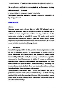
2 Simulation Centered CACE The simulation centered model of the design process presented in this section is based on the fact that different users have different approaches to the design problem. Two major categories are identified: the application engineer, who is focused on getting his application controlled in the optimal way and the algorithm designer, whose main goal is to develop and validate the control algorithm on somc object. The model is shown in figure 1 in the first instance. i.c..
Data
Generator
f
2
(7
0 Physics
Physics
Coll7~’ollerll
Libm rips
Figure 1: Design process model. Algolithm (- -) and application designers points of view. from the application engineers point of view. The model of the design process is centered on the simulator, not in the limited sense of the term, but including the ability to generate real-time code, simulate the dynamics and linearize the non-linear model of the system. The simulator takes a control algorithm and a systcrn model as inputs and produces
results in terms of data and real-time code. The system model is generated by a model generator basing on the physics of the system and blocks from a component library. The results of the simulation are visualized in different ways, as plot of variables or as an animated representation of the actual components of the system. The result is
121
then evaluated against the goals of the system performance. When the goals are met by the simulated results the realtime code is generated in the simulation block and the experimental verification is done. Results obtained here are validated against the simulation using the same visualization module and compared with the goals. Finally, the design should be implemented for production purposes, which may be quite different from the test implementation for experimental verification and rapid prototyping. The application engineer starts with modelling the system to be controlled and ends with the experiments. The starting point of the algorithms developer is different as shown in the figure. The algorithm developer start with determining the goals, and having the control algorithms to be validated some model is chosen for the validation. Iterations are done modifying the parameters or structure of the control algorithm until the goals are met. The control algorithm is then possibly validated through experiments. The two points of view are quite similar in structure but the focus is different. The result of the process should not be just the control algorithms but also some measure of the sensitivity to imperfect initial conditions in the design. The validation results should be presented in a form suitable for documentation purposes. In general there is no single tool covering the computer support to all the design phases mentioned above. In fact, what the user interacts with today is a collection of his tools of choice configured in a way most appropriate to his actual experience and particular project demands. For example in modelling phase the domain-oriented tools may be applied reflecting the nature of the plant to be controlled. This is why inter-operability of CACE tools gains more and more importance. The current trends in software engineering had over the years an impact on discussion on the construction and design of control engineering software. Some of the trends had even an impact on the available tools, however most of them are not yet completely and naturally integrated in the standard tool. A few trends can he mentioned here: visualization and animation tools are used for displaying complcx relations in large data-sets and for animation of simu I tit ions interactive GUI’s have, due to their user friendliness towards the inexperienced users, gained much support, but there still scems to he a need for research on GUI’s that are equally friendly towards the experienced users, The requirements and rationale for supporting animation in control application developments could be summarized a s : There is a need for animation in several areas; for dcmonstrating control performance in larger projects and for gaining a better understanding of algorithms and application both in the research and development area and in the teaching area. What scale should be used? The aim is building a simple visualization methodology for control engineers. As a
.
target not more than 10% of the modelling effort should devoted to visualization. Much work has been done in the area of visualization and animation by people from other domains than control engineering and their tools and results should be used where appropriate and needed. This means that just glue and possible missing parts should be developed from scratch The still stronger technologies for integrating the development process using hardwarc in thc loop (HIL) simulation and rapid controller prototyping (RCP) should be used seamlessly so the animation would work with simulation as well as real world experiments.
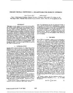
3 The Methodology and Toolkit The proposed methodology consists of two distinct phases: The model development phase and the model/animation run-time phase. In the first of the two phases the simulation model is build and tested. In the prototype implementation this is should be done in Simulink, but basically the ideas should work with any modelling/simulation system. Furthermore the animation model is build and tested this could also be done in several environments, in this case the Cosmo Worlds system is used producing a VRML 2.0 description of the system and scene. The specification of linking between simulation variables and movable parts in the VRML world is now done. The second phase could now be entered by starting the simulation and specifying the viewing parameters to the VRML browser. In the simulation centered control system design model the area covered by the VRML Animation Toolset is shown in figure 2. Note that the data for the animationlvisualization could come from either the simulator or the realworld experiment. A third phase could be introduced i n order to separate the simulation and visualization, this would be helpful when considering large and complex models where is simulation would run considerably slower than real time. In this case the simulation is performed off line and the animation is then performed separately. This will make user interaction with the simulation through the animation browser difficult if not impossible. This kind of user interaction not just with the animation parameters like lighting and camera position but also with the simulated system is one of the very appealing features of the whole concept. However when considering long time simulation or large data sets from i.e. sea trails with an Autonomous Underwater Vehicle it could be useful to have some kind of fast forward or reverse button to be able to focus attention to the interesting parts of the animation. Figure 3 shows the different phases and their relations. As shown it could even be considered intergrating the modelling phase with the two others allowing the user to add parts to or modify the simulated system on-line. This is outside the scope of this paper.
122
f
2
c3
r’? Physics
Physics
Component Libraries
Figure 2: Elements covered by the VRML animation toolset.
Modelling
Modelling
rn
m Modellin
Simulation
I
Visualization
1
I Visualization I On-line or Offline interactiodvisualization
Figure 3: Phases in the use of visualizatiordsimulation framework
A automatic or user adjustable variable level of detail in the simulation and animation could be useful when moving through large sets of data or simulating a long period of time faster than real time. Both the time resolution, the complexity of the simulated model in the simulation as well as the spacial resolution in the animation are parameters to consider when designing this kind of system. The aspect of control is also interesting, is the simulator driving the animation of the other way around and how are several systems simulated. The issue of seamless integration with hardware in the loop simulation and real system components mentioned earlier is also important. One view of the situation is shown in figure 4.
Three levels are distinguished: an off line simulation level
were the system is simulated in for instance Simulink and the control algorithm is implemented using MATLAB/C/tcl or any other suitable language. On the second level called the real time level the system is moved to a HIL platform where the code is generated by RTW and the controller is prototyped and running on a suitable real time platform. The third level is called the real hardware level and includes the real system hardware and the real system controller. The levels could be mixed in different ways in the different phases of the controller design. It is important to note that the visualisation/animation and input actions are split in two distinct parts in order to make the transition between different levels simple. On one side the visualization of the system which is the one being considered in this paper and on the other hand the similar block of the controller. The strict separation into system and controller is equally important for the easy transition between levels. To be able to evaluate the concept and methodology outlined above a prototype implementation has been made using the components shown in figure 7. The toolset is called VRML animation toolset for Simulink and uses java and TCP/IP sockets for communication between Simulink and the VRML model. The use of Simulink enables the use of Real Time Workshop to make the translation from simulation to real-time code..
123
I
System
I
Control
UNIX Simulatio
MATCOM or FSM
Real Timc
Real Hardware 1
I
Figure 4: Hardware-in-the-loop simulation
Figure 5: Simulink model of an AUV with the VRML animation block
4 Prototype Implementation The ideas described above contains much flexibility with respect to choosing the actual parts of the implementation. This is intentional as the emergence and demise of specific software products and the change through new ,version is bound to have a strong impact on the actual implementation. Some generic components of a meta toolset has been distinguished and the elements needed are mapped onto the current available products.to make up the prototype implementation called VRML toolset for Simulink. Elements and their roles in the toolset are shown in figure 7. The elements are VRML standard specification language in version 2.0 facilitates animation of dynamic worlds and both browsers and modellers are available. Cosmo Worlds for modelling the virtual world in native VRML. Cosmo Player for viewing the world in the animation phase.
124
Socket for communication between simu.,tion and animation. Adds flexibility as the simulation and animation could be on separate hosts. The communication across the sockets are pose data. (McLure, 1998) Java for scripting the interface from the VRML World to the sockets. Simulink for simulation using C s-functions for socket communication. This makes it possible to use RTW to automatically generate real-time code for the prototype controller. The specific elements of the prototype implementation are not vital for the concept, other elements could used if needed. However the selected elements gives optimal flexibility and minimize the amount of specialized code needed.
Figure 6: Screen shot of the visualization of the A W design controls for the simulated system and control interface for the controller. I
Simulator I Multi agent I
’
I
+ I 4
I
I
Acknowledgements
Animation browser
The second author gratefully acknowledges the support of EU Euro-Docker contact no. MAS3-CT97-0084.
I
References Brutzman, D. (1999). Home page of distributed interactive simulation dis-java-vrml working group. http://
5 Conclusion
www,stl.nps.navy.miydis-java-vrml/AnnotatedReferences.html#DIS. Carey, R. and Bell, G. (1997). The Annotated VRML97 Reference Manual. MATLAB (1998). Using MATLAB Graphics. The Mathworks Inc,. McLure, D. P. (1998). Clienvserver programming with VRML.http://w ww.webresource.net/vrml/articles/
In this paper the ideas behind and the design considerations for the VRML animation toolset for Simulink presented. The need for animation in control engineering is emphasised and that this should be at a reasonable cost compared to the rest of the modelling effort. The prototype implementation is presented and the each element is discussed. The extensive use of standard readily available software products such as Simulink, Cosmo Player, Cosmo World and java as glue code. The use of sockets for communication adds flexibility to the solution by enable multi computer systems and widening the number of possible platforms (UNIX, Windows, OS9 etc.) for executing the system. Future work include assessment of the added work load for the animation, and the investigation of using VRML to
ScriptSample/vrmlScriptArticle.html. Messner, B. and Tilbury, D.( 1998).Control tutorials in MATLAB, http://www.ecn.missouri.edu/ecn/manual/ctm. Schmid, C. (1999). Virtual control laboratory. http:// www.esr.ruhr-uni-bochum.deNCLab. TWM (1995). Simulink animation blockset make development easier, an it’s free. MATLAB News and notes.
125