This paper presents the development of a cosimulation platform of induction motor direct torque control (DTC) drive. This paper provides advanced modeling ...
Simulation of Direct Torque Control of Induction Motor Using Simulink, Simplorer and Maxwell Software Amit Kumar Singh, Praveen Kumar; C Upendra Reddy; Kashyap Prabhakar Simplorer for co-simulation, by establishing interface between simplorer and Maxwell.
Abstract This paper presents the development of a cosimulation platform of induction motor direct torque control (DTC) drive. This paper provides advanced modeling and simulation tool for induction motor drive. The proposed simulation platform allows a coupled analysis that links finite element analysis (FEA) with the simplorer for the more realistic simulation, analysis and validation. With the help of finite element analysis method (FEM), a three phase induction motor is simulated. The obtained model is also configured in MATALB/Simulink. In this paper, comparison between the Matlab/simulink and Ansys Maxwell simplorer cosimulation is done for speed control of induction motor (IM) based on the direct torque control strategy. Index Terms— Electric machine, induction motor, simulink, simplorer, maxwell.
I.
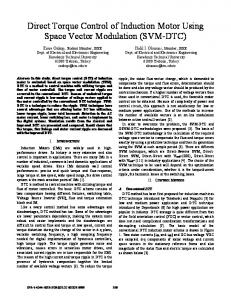
All the analysis presented in this section are based on the d-q or dynamic equivalent circuit of the induction motor represented in the synchronous reference frame [1], [2]. The differential equations produced from analysis of the d-q equivalent circuits are given in (1)-(4):
Introduction
This paper presents the co-simulation of the DTC drive of IM and integration into a common simulation platform. The control algorithms for high dynamic performance electric drive systems are not analyze by the linear models. As the motor behavior is more nonlinear depending upon the drive changing conditions and the effects of magnetic saturation on the control algorithms should be taken into account. Therefore, researchers need advanced cosimulation tools platform which must be capable of analyzing such motor drive models with the highest possible level of accuracy in the design process. The simulation of induction motor drives in Matlab/simulink has been usual for a long time. This software provides a suitable environment for design of controller because of various mathematical tools. But the model of this software for power electronics and motor is ideal which does not depict the practical behavior. On the other hand, Maxwell is design software for electrical motor but its facilities are very low for design of drives and controller. In this way, users of these two softwares cannot simulate the practical behavior of controller, drive and motor all together and therefore, their simulation don’t close to reality. Model of power electronic components is very accurate in simplorer software and it provides an interface connection between simulink and Maxwell that these three softwares can run all together. A direct torque control of induction motor drive has implemented in this environment to demonstrate the efficiency of this three software. This paper presents the development of a simulation platform for direct torque control of a three-phase squirrel cage induction motor drive. The comparison between the Matlab/simulink and Ansys Maxwell simplorer co-simulation is done based on better performance and good time management for the speed control of induction motor (IM) using direct torque control (DTC) strategy. Firstly, the control strategy is developed in Matlab/ simulink for machine model with and without inclusion of saturation effect. Secondly, the same strategy is implemented in simplorer. Finally, the machine model is first created in ANSYS Maxwell, then imported in Page 1 of 6
II. Matlab/Simulink Implementation of IM Drive
Figure 1. d-q equivalent circuit of the induction motor (a) d-axis equivalent circuit (b) q-axis equivalent circuit.
Vds = Rsids + Vqs = Rsiqs +
d λds dt
(1)
d λqs
(2)
dt
Vdr = 0 = Rridr + Vqr = 0 = Rriqr +
d λdr − (ω − ωr )λqr dt d λqr dt
+ (ω − ωr )λdr
(3)
(4)
q is the quadrature axis, Vds is the daxis stator voltage, Vqs is the q-axis stator voltage, Vdr is the d-axis d
Where
is the direct axis,
rotor voltage, current,
iqs
Vqr
is the q-axis stator current,
current, iqr is the q-axis rotor current, is the rotor resistance, reference frame,
ids
is the q-axis rotor voltage,
ωe
Rs
idr
is the d axis stator is the d-axis rotor
is the stator resistance, Rr
is the angular speed of synchronous
ωr is the angular speed of rotor, λds λqs λdr and
λqr are flux linkages. It is assumed that induction motor analyzed as a squirrel cage motor, leading to the rotor voltage in (3) and (4) being zero. The flux linkages in (1-4) can be written as:
λdr = Lridr + Lmids
(7)
λqr = Lriqr + Lmiqs
(8)
inductance,
Te =
3P Lm [iqsidr − idsiqr ] 22
(15)
d ωr P = (Te − TL ) 2J dt Where
P
(16)
is the number of poles,
is the load torque and
J
Te
is the electromagnetic torque,
is the inertia of the rotor and connected
load.
(6)
is the stator self-inductance,
(14)
Lr
(5)
λqs = Lsiqs + Lmiqr
Ls
λqr − Lmiqs
The electromagnetic torque and rotor speed of the machine neglecting mechanical damping can be written as:
TL
λds = Lsids + Lmidr
Where
iqr =
Lr is
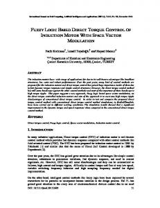
The main goal of this section is to simulate the speed control of induction motor based on direct torque control strategy which must be close to practical motor considering the saturation effects. The direct torque controlled IM drive with voltage source inverter (VSI) is presented in Fig.2. The speed control block is not shown in the diagram.
the rotor self -
Lm is the magnetizing inductance.
The self -inductance in (5-8) can be expressed as:
Ls = Lm + L1s
(9)
Lr = Lm + L1r
(10)
The currents can be written as:
ids =
iqs =
idr =
λds − Lmidr Ls
λqs − Lmiqr Ls
λdr − Lmids
Page 2 of 6
Lr
Figure 2. Block diagram of IM drive based on DTC model. (11)
(12)
(13)
The values of the inductances used in the development of the dynamic mathematical equations for the conventional (without saturation) IM model were assumed to be constant. By so doing, the model fail to take into consideration the saturation effects on Lm. By nsidering the saturation effects, the improved (saturated) model of IM was obtained [3]. By assuming that the magnetizing inductance is constantthe conventional machine model is used to simulate the speed control of induction motor based on DTC strategy and the result of this simulation are compared by those results were obtained by simulation using improved IM model considering the effect of magnetizing inductance saturation. The simulation results of the IM drive with and without saturation machine models are shown Fig. (3) and (4).
Also, Fig. 5(b) and 5(a) shows the flux trajectories for conventional (without saturation) IM model and improved (saturated) IM model respectively.
Figure 3. Matlab/Simulink result of IM drive without saturation (a) Sector evaluation (b) Flux linkage in d-q axes. Fig. (3) and (4) shows deviation in drive performance with and without inclusion of saturation effects. Figure 5. Flux trajectory in Matlab/Simulink of IM drive (a) For convectional (without saturation) IM model (b) For improved (saturation) IM model.
III. Simplorer Implementation of IM Drive The complete DTC drive scheme with speed control is implemented and simulated in simplorer software. The inverter for the IM drive in simplorer software is shown in Fig. 6. The inverter contains 6 IGBT switches with the 6 freewheeling diodes in order to work as three phase inverter . The rest drive strategy is implemented by using different blocks in simplorer. The control logic for the implementation of DTC drive with speed control is same as used in the section II.
Figure 4: Matlab/Simulink result of IM drive with saturation (a) Sector evaluation (b) Flux linkage in d-q axes.
Figure 6. Three phase inverter of the IM drive in simplorer simulator
IV. Maxwell Design of IM The method chosen in this section is the use of ANSYS RMxprt/Maxwell, the fully integrated template-based electric Page 3 of 6
machine design tool to perform a detailed motor design and analysis based on finite element method (FEM). Firstly, the machine geometry is created in the RMxprt in accord with the design similar to the three phase induction machine available in our laboratory. The simulation results which came out from RMxprt are exactly similar to the practical results which were obtained by performing some test on the laboratory motor. This shows that the RMxprt machine model depicts the similar behavior which is close to the real motor available in our laboratory. Thereafter, the machine model created in RMxprt was exported to Maxwell platform. The design details for the machine model created in ANSYS RMxprt/Maxwell is given in appendix. The design of the three-phase induction motor using ANSYS RMxprt/Maxwell are shown in Fig. 7.
(b)
(a)
(c) Figure 7: Design of the three-phase induction motor using ANSYS RMxprt/Maxwell (a) Design of IM using ANSYS RMxprt (b) Winding Design (c) Design of IM using ANSYS Maxwell (Half view).
V. Co-simulation of Maxwell/Simplorer The co-simulation is the most accurate way of coupling the drive with the motor model. This method provides the high accuracy, having the inverter currents from simplorer as source in Maxwell. The transient-transient link enables the use to pass the data between simplorer and Maxwell during simulation. Simplorer and Maxwell will run altogether, the former is act as master and the latter is the slave. At a given time step, the winding currents and the rotor angle are passed from simplorer to Maxwell, the back EMF and the torque are passed from Maxwell to simplorer. The simplorer time steps and the Maxwell time steps don’t have to be the same. Usually, simplorer requires much more time steps than Maxwell [4]. Page 4 of 6
By enabling the transient-transient link, a two way interface is established between the simplorer and Maxwellfor the complete DTC drive scheme with speed control ofinduction motor implementation and simulation. The Ansysy/Maxwell IM model imported in simplorer simulator is shown in Fig. 8.
Figure 8: Maxwell IM model imported in simplorer simulator. The advantage of the co-simulation is that one can get the very close behavior of the motor which is similar to the practical motor.
Figure 10: Flux trajectory of the IM drive in simplorer simulator.
The co-simulation results of sector evaluation and flux linkages in d-q axes for speed control of IM drive based on DTC strategy in Maxwell/simplorer software are shown in Fig.9. Fig. 10 shows the flux trajectory for DTC of IM in Maxwell/simplorer co-simulation. It also reflects the ripple presents in the current waveform. The co-simulation result shows behavior of IM drive very close to the real system.
Summary/Conclusions In this paper, an environment has introduced for simulation of IM drive by using three software, Simulink, Simplorer and Maxwell. It is very difficult for any user to predict the real behavior of the AC drive with the Matlab/simulink simulator. Based on the analysis, the Ansys Maxell/simplorer simulator is suitable for simulation platform for IM drive which will reveals to better performance and advanced simulations for the electric machines and drives.
References 1. 2. 3.
4.
Figure 9: Co-simulation result in simplorer simulator (a) Sector evaluation (b) Flux linkages in d-q axes.
Page 5 of 6
S. D. S. Paul C. Krause, Oleg Wasynczuk, Analysis of Electric machinery and Drive Systems. Willey, 2013. R.Krishnan, Electric Motor Drives: Modeling,Analysis,and control. A. Singh, A. Dalal, R. Roy, and P. Kumar, “Improved dynamic model of induction motor including the effects of saturation,” in Power Electronics, Drives and Energy Systems (PEDES), 2014 IEEE InternationalConference on, Dec 2014, pp. 1–5. “ Anysy-maxwell, software component of ansys/ansoft, maxwell 2d user’s guide.” Tech. Rep.
Appendix 1. GENERAL DATA Given Output Power (kW): 1.1 Rated Voltage (V): 380 Winding Connection: Wye Number of Poles: 2 Given Speed (rpm): 2820 Frequency (Hz): 50 2. STATOR DATA Number of Stator Slots: 24 Outer Diameter of Stator (mm): Inner Diameter of Stator (mm): Length of Stator Core (mm): 135 Number of Conductors per Slot: Number of Wires per Conductor: 3. ROTOR DATA Number of Rotor Slots: 18 Air Gap (mm): 0.5 Inner Diameter of Rotor (mm): Length of Rotor (mm): 135
135 70 56 3
20
4. RATED-LOAD OPERATION Stator Resistance (ohm): 6.20294 Stator Resistance at 20C (ohm): 5.10242 Stator Leakage Reactance (ohm): 5.54202 Rotor Resistance (ohm): 3.15085 Rotor Resistance at 20C (ohm): 2.59183 Rotor Leakage Reactance (ohm): 4.57992 Resistance Corresponding to Iron-Core Loss (ohm): 1.23093e+008 Magnetizing Reactance (ohm): 129.677 Stator Phase Current (A): 2.49668 Current Corresponding to Iron-Core Loss (A): 1.61367e-006 Magnetizing Current (A): 1.53174 Rotor Phase Current (A): 1.90545 Input Power (kW): 1.27125 Output Power (kW): 1.10003 Mechanical Shaft Torque (N.m): 3.61075 Efficiency (%): 86.5316 Power Factor: 0.760893 Rated Slip: 0.0302549 Rated Shaft Speed (rpm): 2909.24 Stator-Teeth Flux Density (Tesla): 0.871484 Rotor-Teeth Flux Density (Tesla): 1.69231 Stator-Yoke Flux Density (Tesla): 1.05827 Rotor-Yoke Flux Density (Tesla): 3.20124 Air-Gap Flux Density (Tesla): 0.431734 Stator Current Density (A/mm^2): 4.2385 Rotor Bar Current Density (A/mm^2): 1.45843 Rotor Ring Current Density (A/mm^2): 6.3158 Estimated Rotor Inertial Moment (kg m^2): 0.00234328
Page 6 of 6