International Conference on Automatic control, Telecommunications and Signals (ICATS15) University BADJI Mokhtar - Annaba - Algeria - November 16-18, 2015
Implementation of Sensorless Direct Torque Control of Induction Motor Using Sliding Mode Observer Abdelkarim AMMAR Electrical engineering Laboratory University Of Mohammed Khider Biskra Biskra, Algeria
[email protected]
Amor BOUREK Electrical engineering Laboratory University Of Mohammed Khider Biskra Biskra, Algeria
[email protected]
To increase the accuracy in a wide speed range operation and to reduce the complexity an inherently sensorless observer is presented without using rotor speed as adaptive quantity [6] contrary to speed adaptive sliding mode observers, Luenberger observers or extended Kalman filters, usually, the speed estimation is the last step of the estimation process, and it is affected by noise and errors [13]. The main goal of this paper is to present sensorless twelve sectors DTC and SMO used for flux, torque and speed reconstruction. The results are examined under simulation and experimental environment.
Abstract— Direct Torque Control (DTC) is one of the most excellent strategies of torque control for induction machine. it aims to provide a decoupled control of torque and flux by the selection of optimum inverter switching tables, there is no need for any complex transformation of current or voltage. However, each vector selected from the switching table may cannot produce the required accurate stator voltage vector to provide the desired torque and flux, this results the ripples in the torque and flux waveforms. This paper reports an improved DTC scheme based on extended switching table to reduce torque fluctuations, where the circular flux vector is divided into twelve sectors of 30 degrees. The design present also proposed observer based on sliding mode approach in order to improve control scheme performance without using sensors for speed and stator flux estimation that increase the cost and reduce reliability. The simulation and experimental results are presented. The platform used for real time control is d-SPACE 1104 along with MATLAB-SIMULINK.
II.
IM MODEL
The equations of Induction motor can be written in the stationary axes reference with stator currents and flux are assumed as state variables, is expressed by ̇
Key words— Induction Motor, DTC, Switching Table, Sliding Mode Observer, DSpace 1104
I.
Abdelhamid BENAKCHA Electrical engineering Laboratory University Of Mohammed Khider Biskra Biskra, Algeria
[email protected]
(1)
Such as (2)
INTRODUCTION
The Direct Torque Control of Induction Motors was proposed by I.Takahashi in the middle of 1980s. The DTC overcomes the drawbacks of FOC such as the requirements of current regulators, co-ordinate transformations and PWM signal generators. DTC also provides high efficiency and good torque control in both the steady state and the dynamic state [1], [2]. However, during steady-state operation, notable torque, flux, and current pulsations occur. They are reflected in speed estimation and in increased acoustical noise. Several solutions are presented in the literature, the minimization of torque ripple is achieved by improvements the number of sectors and switching table is one from this solution. Furthermore, in the last years, sensorless control schemes have attracted the attention of the researchers, not only for the cost and space reductions in the final setup. In fact, when a fault in the position/speed sensor occurs, it may be requested that these devices could continue their operation, possibly with less stringent performance [3], [4]. In this context, the sliding mode methodology, capable of guaranteeing high levels of robustness against disturbances and parameters variations, seems to be well applicable to the design of both the observers and the controllers. Indeed, the use of sliding mode based solutions is widely discussed in the literature [5].
(
) (
)
(3)
[
] (4) [
] (5)
Where:
The electromagnetic torque can be expressed by: ( III.
)
(6)
CONVENTIONAL AND 12 SECTOR DTC STARTEGY
The Direct Torque Control method uses an induction motor model to predict the voltage required to achieve a desired output torque. By using only current and voltage
1
International Conference on Automatic control, Telecommunications and Signals (ICATS15) University BADJI Mokhtar - Annaba - Algeria - November 16-18, 2015 TABLE.II 12-Sector Switching Table
measurements, it is possible to estimate the instantaneous stator flux and output torque. Flux Torque
Increase Decrease Increase Decrease
IV.
,
and and and and
and and and and
FLUX ESTIMATION
The conventional back-emf integration approach of flux estimation can be expressed as ∫
(7)
However, the implementation of an integrator for motor flux estimation is not easy task. A pure integrator has DC drift and initial value problems, the flux estimation result will include DC flux component, and the flux vector is not estimated accurately, which leads to DC current component and severely affects motor operation. This dc component, no matter how small it is, can finally drive the pure integrator into saturation. The initial value problem associated with the pure integrator can be explained as follows. [8], [9].
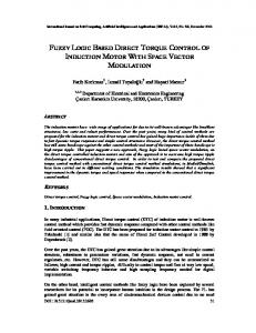
Fig.1 Basic DTC strategy control scheme
The flux and torque are controlled by two comparators with hysteresis two and three level respectively. The switching table shown in Table. I determines the voltage vector to apply based on the position of the stator flux and the required changes in stator flux magnitude and torque .The selected voltage vector will be applied to the induction motor at the end of the sample time in VSI. TABLE I. Switching Table
Sector Error Fig.3. modified flux estimator.
A simple method to remove the DC component from estimated flux is shown in Fig.3, where a high-pass filter ( ) is used to extract the sinusoid. Since the is not ideal and small dc offset could remain, another filtering is added where the remaining dc offset is extracted using a and subtracted from the output of the . This approach was verified to eliminate all dc offset. The frequency should be low enough to avoid filtering the actual sinusoids when operating at low speeds.
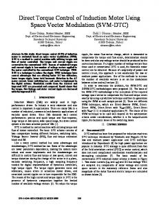
In Conventional DTC there are two states per sector not used and that present a torque ambiguity. The 12 sectors method uses the same algorithm as the conventional method, the circular flux locus was divided into 12 sectors instead of 6 as shown in Fig.2 and all six active states will be used per sector consequently [7].
V.
SLIDING MODE FLUX OBSERVER
A. Sliding Mode Observer Design In this paper the objective of the sliding mode observer is to construct the components of the stator flux and use them for torque and speed estimation, based on the state model of induction motor in rotor reference frame [6] that has stator flux and stator current as state variables.
{
Fig.2. Voltage Space Vector in 12 Sectors case
Therefore, the hysteresis band of the torque is divided into four parts, in 12 sectors DTC, it is necessary to define small and large variations.
(
)
(
)
The state model contains back-emf ( ), in this observer all these terms with rotor speed are considered as disturbances, then an inherently observer Fig. 4 can be express as:
2
International Conference on Automatic control, Telecommunications and Signals (ICATS15) University BADJI Mokhtar - Annaba - Algeria - November 16-18, 2015 ̂ ̂
(
̂
̂
) ̂
̂
̂
(
̂
̂
̂
̂ )
̂
However the computation of the rotor flux derivative is sensitive to noise, so in practice and in order to be useable in the control algorithm the estimated speed has to be filtered by using LPF. In stator flux observer or estimator the rotor flux can be estimate from the stator flux and measured current, as:
{
̂
̂
The estimated torque can be calculated from (6). VI. Fig.4. Inherently Sliding mode stator flux observer
SPEED REGULATION
The used speed controller is PI anti-windup for reference torque generation and to obtain high performance speed control of induction motor by cancel the of integrator windup due to saturation (so-called windup phenomenon) [11], [12].
K is the observer gain, S is sliding surface of the current error, controller is proposed to impose desired error convergence where: ̂ The observer gain has to be large enough under stability condition from Lyapunov analysis.
Fig.5. Speed anti-windup PI controller
By using Lyapunov candidate function that defined in (13) and IM and SMO models (8), (9), (10), (11) and during sliding mode , , K is given as: (|
||
To overcome this phenomenon the strategy consist on the correction of integral action based on the difference between the control signal and the saturation limit Fig.5, the difference value passed through a gain block (tracking time constant ) before arriving as feedback to the integrator.
|)
VII. SIMULATION RESULTS
Where: Flux error
The control scheme is simulated by using Matlab/Simulink software. Simulation results were obtained for a three phase 1.1kW squirrel cage induction motor with characteristics given in Table III.
B. Chattering phenomenon In sliding mode technique an infinite commutation causes the chattering phenomenon and it is undesirable in practice, in order to reduce this problem the traditional sign function is replaced by a softer one related to saturation function [10][14].
{
Table III. Induction motor parameters
P=1.1kW Rs=6.75 Ω Ls=0.5192 H Lr=0.5192 H Msr=0.4957 H
| |
p=2 Rr=6.21Ω J=0.01240 kg.m² f=0.002 V=400 V/230V
The results of sensorless direct torque control (DTC) with sliding mode observer are shown in Fig.6-12, respectively, stator phase current , electromagnetic torque , stator flux, magnitude and estimation error, rotor speed and speed estimation error, finally parameters sensitivity test.
: is a small positive constant represent the width of boundary layer. C. The speed estimator The advantage of SMFO is the unrelatedly with rotor speed and when it needed it can be estimated easily as follow:
3
International Conference on Automatic control, Telecommunications and Signals (ICATS15) University BADJI Mokhtar - Annaba - Algeria - November 16-18, 2015 speeds region from (10,-10 rad/s) and (5,-5rad/s) with load introduction 5.N.m at 0.5s. The estimated speed (16) follows its references, the estimator is robust against the sense reverse and has good accuracy in both high and low speed regions, Fig.11 shows the estimation error with different references values around zero ±0.05 rad/s and it has no influence on the inherently SMO, it mostly depends on the noise level and filtering operation.
Stator phase current(A)
4
2
0
-2
-4 0.2
0.3
0.4
0.5 Time(s)
0.6
0.7
150
.
15
100
10
50
Speed(rad/s)
Electromagnetique Torque(N.m)
Fig.6. The stator phase current
0.8
5 0 -5
0 -50 -100
-10
-150 0
-15 0
0.2
0.4
0.6
0.8
1 Time(s)
1.2
1.4
1.6
1.8
2
0.2
0.4
0.6
0.8
1 Time(s)
1.2
1.4
1.6
1.8
2
Fig.10. Speed response with sense reverse and different references values (rad/s)
Fig.7. Electromagnetic torque
0.15
1.5
1.5
1
1
0.5 0 -0.5
-1
0.4 Time(s)
0.45
0.5
0.55
0.6
Speed estimation error(rad/s)
-0.1
0.2
-1
-0.5
0 Flux axe aplha
0.5
1
1.5
1.4
0.35
0.4 Time(s)
0.45
0.5
0.55
0.6
Speed reference Rs + 100% Rr + 100%
21
20
19
18 0
1.2 Flux magnitude(Wb)
0.3
22
Fig.8. Stator flux component (α,β) and trajectory.
0.1
0.2
0.3
0.4
0.5 Time(s)
0.6
0.7
0.8
0.9
1
Fig.12. Estimated speed in low region with (Rs, Rr) variation test
1 0.8
The parameters sensitivity test is shown in Fig.12, which the rotor speed in low region 20 rad/s with Rs and Rr variation (+100%) at t=0.5s , the instability due to stator resistance augmentation is appear, on the contrary the SMO is insensitive to rotor resistance. This problem can be solved by using online adaptive algorithm.
0.6 0.4 0.2 0 0
0.1
0.2
0.3
0.4
0.5 Time(s)
0.6
0.7
0.8
0.9
1
0.03 Flux estimation error(Wb)
0.25
Fig.11. Speed estimation error
-0.5
-1.5 -1.5
0.35
0
-0.05
0
-1 0.3
0.05
0.5
-1.5 0.2
0.25
at 100 rad/s at 10 rad/s at 5 rad/s
0.1
Estimated speed (rad/s)
Flux axe beta
Stator flux (Alpha,Beta) (Wb)
Fig.6 shows the sinusoids waveform of stator phase current isa with load of 5N.m at 0.5s. The estimated torque Fig.7 has good response at the startup and while speed inversion operation, in the other hand the reduced ripples level is observed as result of using the extended switching table.
at 100 rad/s at 10 rad/s at 5 rad/s
0.02
VIII. EXPERIMENTAL RESULTS
0.01
The proposed control scheme, illustrated in previous sections has been implemented in the Matlab/Simulink software and the results were verified by the experimental tests in the laboratory equipped with the real time interface (RTI) associated to the dSpace DS 1104. The implementation ground of induction motor drive is essentially composed as shown in Fig.13 of: A squirrel-cage IM 1.1 kW, power electronics Semikron converter composed of a rectifier and an IGBT inverter, speed sensor (dynamo tachymeter), however it was not used in sensorless algorithm, magnetic powder break, dSpace DS 1104 with control desk software plugged in personnel
0 -0.01 -0.02 -0.03 0.2
0.25
0.3
0.35
0.4 Time(s)
0.45
0.5
0.55
0.6
Fig.9. Flux magnitude and flux estimation error
Fig.8.9. show that the flux has low ripples level like the estimated torque, the observation is accurate and consistent at different speeds where the estimation error converge to zero between ± 0.025 Wb. The speed test is operated with different references from 100 rad/s to 100 rad/s at t=1s and in low
4
International Conference on Automatic control, Telecommunications and Signals (ICATS15) University BADJI Mokhtar - Annaba - Algeria - November 16-18, 2015 computer, the stator current are measured by Hall type sensors. For reduce the cost of IM drive control system the phase voltage sensors are eliminated, they can be estimated from DC-bus voltage and inverter switching states (Sa, Sb, Sc) [15]. A GW-INSTEK oscilloscope used for obtaining results. The IM parameters are illustrated in Table. III.
Fig.16. stator flux component (α, β).
Fig.17. stator flux trajectory Fig.13. Experimental setup
The experimental results obtained of IM-DTC with stator flux reference of 0.8 Wb are shown from Fig.14 to Fig.21, the Fig. 14.15.16.17.18 illustrate the principles results: stator phase current, flux magnitude, flux component and flux trajectory, angle and sectors in no load condition, in the other hand Fig.19.20.21 illustrate some robustness tests as load torque variation, speed sense reverse and low speed operation. Fig.18. position and sectors
Fig.14. stator phase current Isa (no load). Fig.19. speed, electromagnetic torque and phase current with load application.
Fig.15. stator flux magnitude. Fig.20. speed sense revers (400rpm,-400rmp), position and stator flux.
5
International Conference on Automatic control, Telecommunications and Signals (ICATS15) University BADJI Mokhtar - Annaba - Algeria - November 16-18, 2015 both speed and flux estimation, a robustness in different tests, like: load application, sense reverse and low speed operation. In addition parameters variation, which can be improved in future’s works by online adaptation algorithm. REFERENCE [1] D. Casadei, F. Profumo, G. Serra, and A. Tani”FOC and DTC: Two Viable Schemes for InductionMotors Torque Control,” IEEE Transactions on Power Electronics, Vol. 17, No. 5, September 2002. [2] T. Sutikno, N.R.N Idris, A Jidin, and M.N. Cirstea, “An Improved FPGA Implementation of Direct Torque Control for Induction Machines” IEEE Trans. Ind. Electron., vol. 9, no. 3,pp. 1280-1290, Aug. 2013. [3] C. Lascu, I. Boldea, and F. Blaabjerg “A Modified Direct Torque Control for Induction Motor Sensorless Drive” IEEE Transactions on Industry Applications, Vol. 36, No. 1, January/February 2000. [4] M. Barut, R. Demir, E. Zerdali, and R. Inan, “Real-time implementation of bi input-extended kalman filter-based estimator for speed-sensorless control of induction motors,”IEEE Trans. Ind. Electron., vol. 59, no. 11, pp. 4197–4206, Nov. 2012. [5] O. Barambones, P. Alkorta, “Position Control of the Induction Motor Using an Adaptive Sliding-Mode Controller and Observers”, IEEE Trans. Ind. Electron, Vol. 61, no 12, pp 6556- 6565, Dec 2014. [6] C. Lascu, I. Boldea, and F. Blaabjerg “A Class of SpeedSensorless Sliding-Mode Observers for High-Performance Induction Motor Drives” IEEE Transactions on Industry Applications, Vol. 56, No.9 Sep 2009. [7] R. Toufouti, S. Meziane, H. Benalla " Direct Torque Control Strategy of Induction Motors" Acta Electrotechnica et Informatica No. 1, Vol. 7, 2007 pp:1-7 . [8] B. Singh, S. Jain, S. Dwivedi “Torque ripple reduction technique with improved flux response for a direct torque control induction motor drive” IET Power Electron., 2013, Vol. 6, Iss. 2, pp. 326–342 [9] J. Zhang, H. Jia “Study on Nonlinear Perpendicular Flux Observer for Direct-torque-controlled Induction Motor” International Journal of Nonlinear Science Vol.6 (2008) No.1, pp.73-78. [10] N. Inanc, “A robust sliding mode flux and speed observer for speed sensorless control of an indirect field oriented induction motor drives” Electric Power Systems Research 77 (12) (2007) 1681–1688. [11]A. Hmidet, R. Dhifaoui, O. Hasnaoui “Development, Implementation and Experimentation on a dSPACE DS1104 of a Direct Voltage ControlScheme” Journal of Power Electronics, Vol. 10, No. 5, September 2010. [12] V.C. Ilioudis, N.I. Margaris “Antiwindup Speed Technique for Sensorless Control of Synchronous Machine Using Saturation Feedback”. 20th Mediterranean Conference on Control & Automation, 3-6 July 2012. [13] C. Picardi, F. Scibilia, Sliding-mode observer with resistances or speed adaptation for field-oriented induction motor drives, in: Proc. of the 32nd IEEE Annual Conf. on Ind. Electron. IECON’ , , pp. –1486. [14] A. Benchaib, A. Rachid, E. Audrezet, M. Tadjine, “Realtime sliding-mode observer and control of an induction motor”, IEEE Transactions on Industrial Electronics 40 (1999) 128–138. [15] M. Hafeez, M. N. Uddin, N. A. Rahim, H.W. Ping, “Self-Tuned NFC and Adaptive Torque Hysteresis-Based DTC Scheme for IM Drive,” IEEE Trans. Ind. Applications, Vol. 50, No. 2, March/April 2014.
Fig.21. Low speed operation (200rpm, 400rmp), stator phase current.
Firstly Fig.14 shows the stator current (1div=1A) speed (1000 rpm) and without load it’s clear that waveform is sinusoids, it is improved by using the proposed filter instead the pure integrator in the voltage model of SMO. Fig.15 shows the flux magnitude, which follow the reference value 0.8 Wb (1div=1Wb) with stator component (α,β) and trajectory are shown Fig 16.17, we can see also the good waveform. Fig.18 shows the stator flux angle (1div=1rad) and switching table sectors. The Fig.19 shows the of introduction and suppression of load toque 5 N.m, the figure from the top illustrates: rotor speed 1000 rpm (1div=500 rpm), estimated electromagnetic torque (1div=5 N.m) and the phase current, it is clear that the torque follows the load value while the speed rejects the disturbance quickly and the current responds to load’s application. The next test is the speed sense reverse (400rpm, 400rpm) Fig.20, the figure illustrate from the top rotor speed (1div=1000rpm) , flux angle (1div=5rad) and the flux (1div=0.5Wb) , it can be noted that the sense reverse of speed, angle and flux was in 10ms, this indicates to the quick response of DTC. The last test is the low speed operation in Fig.21, the figure illustrates the speed (1div=500rpm) and phase current 200 rpm (≈21rad/s), it’s a clear that the speed response is good and also current waveform, we can notice small augmentation in current ripple level and transient state while reference variation to 400 rpm. Generally the proposed sensorless control scheme associated with SMO has good response, robustness and accuracy in different operating condition, different speed regions, speed sense reverse and load application, with good current waveform, in the other hand the simulation test shows the level of estimation errors and sensitivity duo to resistance variation is acceptable except Rs in very low speeds value. IX. CONCLUSION This paper presents a modified sensorless control strategy, it composed of direct torque control method based on increasing the number of switching table’s sectors, in order to improve the control performance such as: reduce the flux, torque and current ripples, get fast dynamic and good response in low speed region. In the other hand, an inherently sliding mode flux observer was presented as a sensorless algorithm. This latter does not require the speed’s adaptation mechanism. The effectiveness and performances of control scheme have been verified by simulation and experimental investigation. The results show good accuracy and acceptable errors level in
6