Simulation Platform for MIMO Systems Miguel Bazdresch Insituto Tecnol´ogico y de Estudios Superiores de Occidente. Perif´erico Sur 7575, Guadalajara, Jalisco, M´exico. Tel: +52 33 3669 3508 email:
[email protected] Georges Rodr´ıguez-Guisantes Ecole Nationale Sup´erieure des T´el´ecommunications. 46, rue Barrault, 75634 Paris Cedex 13, France Tel: +33 1 45 81 73 97 email:
[email protected] Abstract A computer simulator package for MIMO systems is presented. This simulator is highly configurable, easily extensible, and can generate exhaustive performance and complexity measurements. Examples of use and capabilities are shown. The simulator’s source code has been released to the research community under an open-source license.
1. Introduction Computer simulation is an essential tool when studying the performance and complexity of the different receivers that have been proposed for use in multiple-input, multipleoutput (MIMO) telecommunication systems. Simulation also has an important role to play in architecture exploration, indicating which portions of the algorithms need to be optimized, and where the bottlenecks are found. In this paper, we present MSIM, a powerful simulator platform that has been successfully used to estimate the performance and complexity of several MIMO algorithms, and which is designed to be extensible, making it very easy to add new algorithms or new functionality. This simulator is presented to the community under the MIT’s open source license [1], with the aim of attracting improvements and contributions from other researchers. We present our reasons for writing a MIMO simulator from scratch, instead of using existing tools, in Section 2. In Section 3 we make a brief recount of the simulator’s capabilities. Some examples of what can be done with MSIM are presented in Section 4. Finally, we state our conclusions
in Section 5.
2. Justification There are many proven computational tools, commercial and open-source, that can be used to simulate a MIMO communications system. We have found, however, that it can be very difficult, or even impossible, to use these tools for detailed architecture exploration and complexity estimations, because they are intended to solve more general problems. For instance, one might want to use the LAPACK [2] package of mathematical functions to build a simulator. One must then consider how LAPACK performs the calculations needed by the simulator. For instance, there is the problem of finding the Givens rotation of a matrix, needed for calculating the QR decomposition. A Givensprotation is defined by a pair p of functions, c(f, g) = f / f 2 + g 2 and s(f, g) = g/ f 2 + g 2 , where f and g are complex numbers [4]. This apparently straightforward calculation needs to be done very carefully in some limit cases, such as when f or g are very large, or when one of them is zero [6]. The LAPACK code for the Givens rotation takes all these limit cases into account, providing extremely efficient and reliable code as a result. In MIMO communication systems, however, it is known that these limit cases will almost never appear. MSIM needs to be able to find the QR decomposition of a random matrix whose (complex) elements have a Gaussian distribution with zero mean and variance 0.5 per dimension [3]. Since, in this case, f and g will almost invariably be small and different from zero, the general solution implemented in LAPACK results in considerable inefficiencies.
3. Simulator Capabilities 3.1. Organization MSIM is divided into modules, which are called, in order, from a master controller module. First, configuration is carried out from a text file that contains the commands to be executed; then, the remaining modules are executed in a loop until a certain condition (typically, a number of bit errors) is met. The modules present at this time are: information source, channel coder, modulator, channel, channel estimator, receiver, demodulator, error counter, and a module that reports all the results. Each module’s capabilities can be easily configured and expanded. The receiver module presently includes several variants of a V-BLAST receiver [3] and a receiver based on lattice decoding [5]. The modules are functional enough to create most typical simulation scenarios. Some of the main parameters that can be configured are: • Selection of range of block sizes • Selection of range of average signal-to-noise ratios (SN R) • Type of constellation for each transmit antenna • Average power per constellation symbol • Number of errors to simulate
3.2. Reporting When it is finished, the simulator produces extensive reports of all performance and complexity measurements. These reports are arranged in such a way that producing graphics from them, using common plotting utilities, is very easy. Among the results provided are: bit-error rate (BER), block-error rate (BLER), true average SN R, and detailed complexity measurements, which include counts of all arithmetic and memory operations performed. Extensive
debug information can be produced on demand, including intermediate values of calculations. Most of the debugging and complexity functions can be disabled, if simulation speed is a priority.
3.3. Performance On a computer equipped with an Intel Pentium 4 running at 2.4GHz MSIM can simulate a V-BLAST receiver at around 2.5 million bits per second for a system with 4 transmit and 4 receive antennas, and 10 vectors per block.
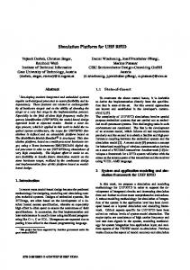
4. Simulation Examples 4.1. Performance estimation As an example of performance simulation with MSIM, consider a MIMO system with 4 transmit and 6 receive antennas, where each transmitter uses a 16-QAM signal constellation of average energy equal to 1, and with a block size equal to 10 vectors (so that a block comprises 160 bits). Fig. 1 shows a comparison of two receivers, V-BLAST and a lattice decoder. The performance measure being used is the block error rate (BLER), that is, the probability of at least one bit per block being in error.
10-1
BLER
Furthermore, modifying LAPACK to eliminate the unwanted functionality can prove to be harder than writing the code from scratch. Writing all the mathematical functions we need from scratch allows us to tailor the code precisely to our needs, and facilitates the task of estimating its complexity. For this reason, we decided to create MSIM from scratch; we wish to contribute this simulator to the research community in order to help others facing the same questions that we did.
10-2
10-3
VBlast ML 14
15
16
17
18
19
20
21
22
23
24
SNRAVG
Figure 1. Comparison between V-BLAST and a lattice-decoder algorithm. The V-BLAST estimates for BLER produced by MSIM coincide with other results reported elsewhere, for example in [9].
4.2. Complexity measurements Figures 2 and 3 show how V-BLAST compares with the lattice-decoder receiver, both in total number of arithmetic operations (sums, multiplications, and square roots) and memory accesses. MSIM can also produce detailed
statistics for each type of operation. The numbers shown are averages per bit of information transmitted.
larger block sizes, there is almost no advantage. The conclusion is that for this particular MIMO system, the LLL reduction has no tangible benefits.
120 260
110
250 240
90
230 220
80
Arith + Mem Operations
Arithmetic Operations
100
70 60 50
190 180
160
VBlast
150
ML 14
15
16
17
18
19
20
21
22
23
24
SNRAVG
L=100, LLL L=100, no LLL L=10, LLL L=10, no LLL
140 130
Figure 2. Comparison of number of arithmetic operations required for V-BLAST and a lattice-decoder algorithm.
14
15
16
17
18
19
20
21
22
23
SNRAVG
Figure 4. Effect of block size L on the complexity of the lattice-decoder algorithm As another example of the kind of architectural exploration possible with MSIM, it was found that, for the VBLAST receiver, 92 multiplications are needed per received bit. However, 24% of these multiplications are done during matrix multiplications. This allows an estimate of the maximum gain in performance that can be obtained by investing architectural resources in a fast matrix multiplier.
130 120 110 100
Memory Operations
200
170
40 30
210
90 80 70
5. Conclusions
60 50 40
VBlast ML
30
14
15
16
17
18
19
20
21
22
23
24
SNRAVG
Figure 3. Comparison of number of memory accesses required for V-BLAST and a latticedecoder algorithm.
4.3. Architecture exploration To illustrate how architecture exploration can be done with MSIM, consider the following problem. The latticedecoder receiver can potentially benefit if the channel matrix is reduced according to the LLL criteria [7], [8]. The LLL reduction is very expensive, but it only needs to be done once per block, and the decoding of each block is faster when the channel matrix is reduced. The architectural question arises: in which cases is it worth the investment to carry out the LLL reduction? Fig. 4 can help answer this question. As can be seen, for block sizes of around 10, there is a substantial increase in complexity when the LLL reduction is carried out. For
In this paper, we have presented a simulator for MIMO communications systems with the capacity to estimate algorithmic complexity and error performance, and to carry out architecture exploration. The source code of this simulator has been released, with the intention of attracting improvements from the research community. Some examples of what can be done with current capabilities have been shown. The MSIM simulator can be found at: http://www.enst.fr/˜rodrigez/msim.html.
References [1] “The MIT Open-Source License,” [Online] http://opensource.org/licenses/mit-license.php, 2005 [2] “LAPACK: Linear Algebra Package,” http://netlib.org/lapack/index.html
[Online]
[3] G. D. Golden, C. J. Foschini, R. A. Valenzuela and P. W. Wolniansky, “Detection algorithm and initial laboratory results using v-blast space-time communication architecture,” Electronics Letters, vol. 35, no. 1, pp. 14–16, Jan. 1999.
[4] G. H. Golub and C. F. Van Loan, Matrix Computations, 3rd ed., The Johns Hopkins University Press, 1996. [5] E. Agrell, T. Eriksson, A. Vardy and K. Zeger, “Closest Point Search in Lattices”, IEEE Trans. Inf. Theory, vol. 48, pp. 2201-2214, August 2002. [6] D. Bindel, J. Demmel, W. Kahan and O. Marques, “On computing Givens rotations reliably and efficiently”, Technical Report CS-00-448, University of Tennessee, October 2000. [Online] Available as LAPACK Working Note 148, http:// www.netlib.org/lapack/lawns/lawn148.ps [7] H. Cohen, A Course in Computational Algebraic Number Theory, Springer-Verlag, 1995. [8] A. K. Lenstra, H. W. Lenstra, Jr., and L. Lovsz, “Factoring polynomials with rational coefficients”, Math. Annalen, vol. 261, pp. 515534, 1982. [9] N. Boubaker, K.B. Letaief, and R.D. Murch, “Performance of BLAST over frequency-selective wireless communication channels”, IEEE Tran. Comm., vol. 50, pp. 196-199, February 2002.