embedded software is hand coded using the model as specification. ... has a history of few large programs, tightly ... product development program with a large.
Simulink as a Core Tool in Development of Next Generation Gripen Henric Andersson (Systems Engineer, Saab Aerosystems, Linköping, Sweden) Anders Weitman (Systems Engineer, Saab Aerosystems, Linköping, Sweden) Johan Ölvander (Department of Mechanical Engineering, Linköping University, Sweden)
Abstract In the planning and concept study phases of the next generation Gripen fighter aircraft, methods and tools studies have been performed. Capabilities and limitations of the Simulink toolset have been evaluated to explore how it can support model based systems/software engineering. In this paper, three different approaches of Simulink usage for functional development are presented: 1) The functional oriented systems modeling and simulation approach where the function is in focus; complete enough to be simulatable, but abstract from an implementation point of view. 2) An implementation oriented specification approach that is based on a modeling framework with predefined system architecture, scheduling, data types and rules for discretization. The resulting embedded software is hand coded using the model as specification. 3) Similar to approach two but here the embedded software is automatically generated using a high quality code generator. The driver for choosing approach is threefold; high quality, short development time and low cost. Some experiences based on these prerequisites are presented, mainly concerning the aspects of scalability, such as; model architecture, license model and project ramp-up challenges. The results are also compared to the existing SystemBuild based development environment. When introducing high-end engineering practices and tools such as Simulink in an organization developing safety-critical products, it is important to make sure that also basic management practices (e.g. Requirements-, Configuration- and Change Management) are thoroughly handled. Finally, some needs/suggestions for further improvements are discussed.
Keywords
Gripen, Simulink, MBD, SysML.
1 Introduction
This paper presents the results from an evaluation of different Model Based Development (MBD) approaches for systems/software modeling. Simulink is the core tool of the evaluation with the Gripen aircraft as the example application. The work is carried out in the Gripen Next Generation (NG) program at Saab Aerosystems. The paper presents insights gained from one industrial application at one company; however the situation at Saab is not unique. Most manufacturing industries are today facing a global competition which put demands on high quality, short development time and low cost. At the same time the level of complexity of products are increasing, both from software, hardware and user perspectives. 1.1 Saab Aerosystems Saab Aerosystems develops and produces aircraft systems – the company’s current main product is the JAS 39 Gripen lightweight multirole fighter aircraft. Traditionally, the company has a history of few large programs, tightly coupled to a single customer - the Royal Swedish Air Force. Exports have been the exception rather than the rule. The commercial environment for Saab Aerosystems is now changing in several ways: • New products are developed, such as Unmanned Aerial Vehicles, which leads to a need of reusable components • The Gripen program is expanding into a multi-customer environment which is forcing Saab to improve product variants handling. • Customers expect Saab to identify, fund, and develop new capabilities rather than traditional customer-paid development. There is an increasing need of demonstration of new functions and products including prototyping, simulation and visualization in software based environments. As a consequence of the changes summarized above there is a drive to improve engineering productivity and quality. The introduction of
MBD and model reuse is considered to have high potential. 1.2 Gripen overview Here is a short description of some of the properties of the Gripen aircraft and enhancements introduced with Gripen NG. Technical complexity: • ~3 M Lines of Code (embedded) • >30 computers • Five data bus communication • On-condition maintenance • Back-up systems for redundancy • Role equipment (“plug-and-play”) Features of Gripen NG are for example: • Increased fuel capacity and payload • Increased combat range and endurance • A more powerful engine • Upgraded avionics relying on an open and modular architecture providing ease of integration of new equipment and systems • Fully integrated advanced sensors and weapon fusion, including AESA radar 1.3 Problem formulation The main challenge addressed with this work is “what modeling method is the best when introducing a high-end workflow/tool to a product development program with a large amount of old (legacy) systems/components” The rest of this paper is outlined as follows; section 2 presents the rational to why Saab introduces MBD, section 3 defines the three studied approaches and sections 4 and 5 discusses aspects of the evaluated approaches. Section 6 suggests improvements in the Simulink tool-set and section 7 concludes the results.
2 Rational for introducing Model Based Development
Driving objectives from a business/project perspective is the efficiency view: high quality, short development time and low cost. Objectives from the safety, certification and quality assurance perspective are understandable design and conformance to standards.
These high-level objectives are supported by the MBD methodology in the following ways: fewer faults during design due to continuous "debugging" using simulation fewer late design changes due to early model-based verification/validation increased reusability higher abstraction leading to improved problem insight and communication improved collaboration between engineers and across technical domains 2.1 MBD history at Saab A major Saab internal change initiative, described in (Backlund, 2000), called EMPIRE was conducted over the period from 1994 to 2000. EMPIRE was connected to the research programs “Lean Aircraft Research program”, (LARP, based at LiTH, Sweden) and “Lean Aircraft Initiative” (LAI, based at MIT, USA). With the EMPIRE project, a set of systems engineering, modeling and analysis techniques/tools were introduced and worth to be mentioned is the design environment based on MATRIXx/SystemBuild (National Instruments, 2008) described in (Andersson and Sundqvist, 2006). Saab Aerosystems has taken a strategic decision to evaluate Simulink (MathWorks, 2008) for several reasons: SystemBuild (which is used today to develop the flight control system as well as the general systems computer in Gripen) has not been developed in any noticeable extent Simulink is the de facto tool for model-based development in many domains with a large user community in industry and academia customers requesting Saab Aerosystems to deliver Simulink models there is a need for a state-of-the-art high-end modeling tool to render a more effective development process in new domains (such as development of tactical systems within the “Gripen Avionics Demonstrator” project) 2.2
Methods and tools improvement initiatives Over the last years, further improvement initiatives related to MBD have been conducted,
establishing a new engineering environment in which MBD will exist. Examples are: • Software Configuration and Change Management with Dimensions by (Serena 2008) • Requirements Management with DOORS by (Telelogic 2008) • Systems modeling with SysML and Rhapsody by (Telelogic 2008) The ongoing process, methods and tools change program at Saab Aerosystems is called “Model Based Systems Engineering”. It integrates a range of improvement initiatives grouped into modeling domains and the Simulink evaluation discussed in this paper is mainly connected to the control design domain. 2.3 Prerequisites A basic prerequisite for development of airborne systems is “Software Considerations in Airborne Systems and Equipment Certification”, (RTCA DO-178B, 1992) and it defines a software tool as: “A computer program used to help develop, test, analyze, produce or modify another program or its documentation. Examples are an automated design tool, a compiler, test tools and modification tools.” In section 12.2 of DO-178B software development tools are defined as: “Tools whose output is part of airborne software and thus can introduce errors into that airborne software.” The principles of DO-178B have to be met by any modeling approach.
3 Modeling approaches
The three evaluated approaches are all considered as “best practice” and are based on experience from earlier projects, influenced from research projects, e.g. SPEEDS (Engel et. al. 2007) and (Henzinger and Sifakis, 2007) but also discussions with partners/suppliers such as Airbus and The MathWorks. To illustrate some differences in modeling approach, a small example model is provided, consisting of: • One input and one output • Time delay (1 second) • Integrator • Look-up table x=[-1, 1, 4, 8], y=[-4, 4, 7, 8] These are considered as the low level requirements (LLR) according to DO-178B. In
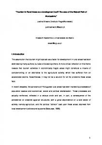
addition, a constraint is that the application execution frequency is 25 Hz. 3.1 First approach - functional oriented In the first approach, A1, the function is in focus, complete enough to be simulatable, but abstract in the sense that it does not include implementation details such as discretization, scheduling and all data types used at target. To implement functions modeled in this way (as embedded software) further detailed design work is needed through modeling or by traditional software design. 1 In 2
1 s Transport Delay
Integrator
1 Out 2 Lookup Table 1
Figure 1. Time continuous model The example model shown in figure 1 is made from continuous standard blocks in Simulink. Aspects considered in this type of model are typically of mathematical or physical interest, such as the input/output relation (transfer function in terms of time or frequency), the meaning and units of signals. Usage is often simulation based, such as Simulation Based Optimization (SBO) (Gavel et al. 2006, and Krus and Andersson 2004) or analysis through linearization and transformation to the frequency domain (eg Laplace transform). 3.2 Second approach - intermediate The second approach, A2, is based on a given modeling framework with predefined system architecture, scheduling, data types and rules for discretization. The actual target code implementation is manually done using the model as specification. Code generated from the model is used in simulators and for software verification purposes. 1 In 2
DELAY 1 sec
INTEG
1 Out 2 Lookup Table
Figure 2. Intermediate model type In figure 2 the model is specified in a time continuous “language”, through user (Saab)
defined library blocks. Each block has well defined LLR:s, test, description and discrete implementation rules. These rules together with modeling guidelines and test environment build the modeling framework that enables the function to be designed and tested against the high level requirements. Many of the low level tests may be reused through the library. The true implementation (source code for target) may be done in an arbitrary programming language. 3.3 Third approach - code generation Even in the third approach, a similar framework as in A2 is defined, but high quality target code is generated automatically by a tool such as Embedded Coder or SCADE (Safety-Critical Application Development Environment). 1 In 1
-25 Z Integer Delay
K Ts z-1 Discrete-Time Integrator
1 Out 1 Lookup Table
Figure 3. Time discrete model aimed for code generation Discrete blocks from the Simulink standard block set are used in the example model shown in figure 3. This model is aimed for detailed software definition, so data types, execution rate and test-points are part of the model. 3.4
Mapping the different approaches to the development process The development process in systems/software engineering could be described in different ways. One common process model is the stepwise model including the steps; requirements analysis, system design, software design and implementation/realization. The three approaches maps differently to this development process as shown in figure 4.
Process step
Approach A1 A2 A3
Requirements Analysis System Design Software Design Implementation Realization
Legend: Strong support Weak support Figure 4. Mapping of modeling approach to development process activities As shown in figure 4 the first approach is best suited in the analysis step of the development process whereas the third approach maps best to the software design step.
4 Aspects on the studied approaches
The approaches are here compared based on a number of typical activities in an aircraft development/upgrade project. 4.1 Modeling/Simulation Simulation of functions is often carried out in a closed loop model (actuator, plant, sensor & software) where hardware/equipment models are continuous components and the software is an algorithm. As an algorithm is a series of specified instructions it takes inputs and deliver outputs, but its implementation may differ in terms of accuracy, required memory and robustness. All approaches has relevance, but for different aspects of this activity.
4.2 Review From a formal quality/process perspective (based on ARP and DO-178B) it is necessary to have reviewable documents/printouts from the model. Also from the more informal needs, the model must be understandable so new employees, consultants or users of the function easily may “read” it, and an abstract model (A1) is often more useful for an overall understanding. 4.3 Verification The verification of a function is done in steps where the last steps usually consist of expensive flight tests, which should be reduced in favor of cheaper methods. These include open-, closedand “hardware in the”-loop simulations, rig tests and, where applicable, by means of tools based on formal methods such as “Design Verifier”, a verification tool integrated with Simulink. 4.4 Knowledge overlap To reduce potential misunderstandings in the handover from systems thinking to software thinking the model should overlap those domains as much as possible. With this principle, the model is the common source of understanding, and consequently, A2 is most valuable in this aspect. 4.5 Tool version updates Usage of high-end engineering tools such as Simulink can substantially contribute to meeting the overall business objectives discussed previously. However, in a product with long lifetime (a fighter aircraft may be operational for 30-40 years with sufficient upgrades) those tools may add unwanted extra costs to the overall lifecycle costs of the system/software due to tools update and extra integration work. For example, updating a code generation tool to a new version will lead to (more or less) different code being generated. If the tool is used for generation of embedded software for a safety-critical airborne system, the tool update will require reverification of the code. In large systems this reverification can lead to considerable costs. Looking at the modeling approaches from a tools update perspective, A1 is the least vulnerable approach since changing the modeling tool will not directly change the underlying product. A2 is
slightly more problematic than A1 since changes to the tool might not work with the existing architecture. Since A3 relies on the tool for generating code, this is the approach which is most vulnerable to tool changes.
5 Discussion
Here some issues relevant for the studied approaches are discussed, even though there are several more aspects to be balanced when designing a final workflow/tool chain. 5.1 Tool integration and dependencies Besides costs associated with re-verification due to changes in a certain tool, tool upgrades might also lead to unwanted costs in the case of a tightly integrated tool chain. This is especially true when integrating tools from different tool providers. On one hand, an optimized and efficient tool chain can lower the development time and costs. On the other hand, upgrades to one or several tools can lead to difficulties to upgrade and keep in pace with the development of the tools. Tool integration must therefore be thoroughly considered. A solution to this dilemma might be to (as far as possible) rely on mature standardized interfaces rather than tool vendor specific interfaces which are more likely to change over time. 5.2 License models High-end engineering tools are of course not free of charge. In a large organization with many engineers, license and service fees form a considerable cost. This cost must be compared to the contribution to lowered development costs and time obtained by utilizing MBD tools. Comparing the three different approaches from a licensing perspective, A2 and A3 are more expensive due to the need for code generation tools. Furthermore, the current license model of the Simulink code generation tool locks the licenses for a considerable time after use, which render it more difficult and expensive to use in approaches A2 and A3. For approach A1, the code may be produced by a small number of specialists or even by support of other tools such as SCADE or SystemBuild.
5.3 Organizational challenges A general challenge when introducing new methods and tools in an organization is to get the right balance/timing. Too rapid introduction without enough adjustment of existing processes, and adequate training, may lead to unstructured information and engineering affecting the quality and resulting in costly re-work. On the other hand, too thorough work on process development, documentation and training takes time and may not give the expected result in the end. Introduction of high-end engineering methods and tools are complicated and require an iterative approach where the capabilities of the tools are evaluated to see how they can be used to meet the requirements and vice versa. Some principles for introduction of new tools and methods are: • create a deployment plan covering activities to support evaluation, introduction and establishment • get the organization's understanding that the positive effects are not reached prior to an successful establishment; during the evaluation and introduction phases, the efficiency will instead decrease • ensure correctness of developed methods and tools support by evaluation in close cooperation with real product projects • develop and introduce changes stepwise • provide just-in-time training adopted to the needs of the users • rely on “light” tool integrations 5.4 Modeling guidelines Clear rules defining the way of modeling must be established prior to project start. There is a risk that engineers try to use the model/tool to document information that could be managed better with traditional specification methods. Simulink allows the same specification or intended design to be modeled in different ways, for example, logics may be modeled with logical operators, truth-tables or by Embedded Matlab Functions. Time must be invested in evaluating alternative ways of modeling the system/software so that important aspects such as safety-critical considerations are fulfilled. Resources are therefore needed for developing guidelines and teaching the selected methods.
Doing so will lead to more consistent models, increased reusability, easier integration and making it easier to rotate engineers between projects. To aid the engineers “good modeling”, the guidelines should include a rational as well as information on which guideline rules are important for which modeling approach. For example, if approach A1 is to be used, rules concerning modeling techniques and settings important for code generation are probably not important. 5.5 Simulink compared to SystemBuild The existing development environment, mainly for flight control functions, based on SystemBuild (SB) is reported in (Andersson and Sundkvist 2006). It is compared to a Simulinkbased environment (hereafter called SL) with the following findings: • SB may produce ADA-code as well as Ccode • SL is a more widely used tool and more engineers have previous experience of SL than of SB • Model restructuring is more easily done in SB due to a more object oriented metamodel • The license model of RTW Embedded Coder (SL code generator) is inflexible compared to SB. • SL has better support for software verification through the extension products “Design Verifier” and “PolySpace” • There are a more cleare development roadmap for SL than for SB 5.6 Long term support For a company like Saab Aerosystems developing products with very long life-time, the risk of tools becoming obsolete leading to expensive migrations is of course a problem. Selecting high-quality and mature development tools from stable tool providers with a large costumer base is therefore important. But the market is difficult to predict and tool provider sometimes acquire each other (IBM buying Telelogic being one recent example).
6 Suggested improvements
Here some needs/suggestions for further improvements are discussed. 6.1
Enumeration types and complex data structures For control design, standard signal data types such as integers, floats, and booleans are usually sufficient. For other modeling domains, other data types may be required. One example is modeling the tactical functions in the Gripen aircraft. These functions typically include a lot of decisions, looping over data elements and interfaces to databases with complex data structures. Native support for enumeration types and composite data interfaces is therefore needed for Simulink to be really useful in this area. Please note that this evaluation was performed using Simulink R2007b. The version R2008b of Simulink is stated to have some support for enumerated data types; however an evaluation of the new version is out of scope for this paper. In modeling approaches A1 and A2, control over the generated interface is not as important as for approach three. The lack of enumeration types can however affect the readability of the models in all three approaches. 6.2 Architecture design and scalability To maintain and further develop large scale models as the system evolves, requires model restructuring from time to time. Simulink has poor support for architecture design and restructuring. As an example it is impossible, in Simulink, to do reverse of the modeling function “create subsystem”, a basic feature in other tools such as SystemBuild or UML-based tools. There should however be a potential to integrate Simulink to the systems architecture modeling means evolving with SysML (OMG, 2006) and (Herzog, 2005). 6.3 Verification For control design type of modeling, SystemTest and Simulink V&V are useful tools. For requirement-based verification of models of e.g. tactical functions, these tools are not quite sufficient. To verify a model with complex interfaces and lot of decisions and states in an efficient way, a test harness with the ability to
specify test inputs and expected outcome for each execution step on a signal per signal basis is needed. This kind of harness can be implemented using Matlab scripts but a better native support in the tools would be beneficial to improve productivity.
7 Results and conclusions
To summarize and compare some of the discussed aspects of the different approaches, Table 1 is provided. Approach
Aspect System review
A1
A2
A3
+
–
Software review
–
+
Closed-loop simulation
+
Impact on existing practices
+
–
–
Tool dependencies
+
+
–
Fewer coding errors
–
+
+
Function & document consistency
–
+
+
Need for guidelines/settings
+
–
–
License model
+
–
–
Table 1. Comparison of effect for some important aspects Legend: + –
Positive effect Negative effect
The conclusion is that no one of the studied approaches is superior. In an existing environment there is a tradeoff between state-ofthe-art methods/tools and traditional methods mainly for legacy components. Taking a too large step may lead to a difficult differences in workflow for different components of the same product.
8 References
- Andersson H. and Sundkvist B.G., Method and integrated tools for efficient design of aircraft control systems, Proceedings from ICAS, Hamburg, 2006. - Backlund G, EMPIRE, ISBN 91-7219-676-9, Linköping, 2000. - Engel A., Winokur and M., Döhmen G. and Enzmann M., Assumptions / Promises - Shifting the Paradigm in Systems-Engineering, INCOSE 2008 - Gavel H., Ölvander J., Krus P., Optimal Aircraft Fuel System Design, AIAA Journal of Aircraft, vol 43., No5, pp. 1334-1340, 2006. - Henzinger T.A. and Sifakis J., The Discipline of Embedded Systems Design, Computer, October 2007, pp. 32-40. - Herzog E, and Pandikow A, SysML - an Assessment, Proceedings of the 15th annual International Symposium of the International Council on Systems Engineering, INCOSE, 2005. - Krus P. and Andersson J., Simulation based optimisation for aircraft systems, SAE 2003 Transactions Journal of Aerospace, pp 461-470, 2004. - The MAthWorks, Simulink – Simulation and Model-Based Design, http://www.mathworks.com/products/simulink/ (2008-10-26) - National Instruments, MATRIXx suite, www.ni.com/matrixx (2008-08-16) - OMG, Systems Modeling Language (OMG SysMLTM) Specification, Final Adopted Specification ptc/06-05-04, OMG, 2006. - RTCA/DO-178B Software Considerations in Airborne Systems and Equipment Certification. Radio Technical Commission for Aeronautics, RTCA, Washington DC, USA, 1992. - Telelogic, DOORS, www.telelogic.com/products/doors (2008-08-16) - Telelogic, Rhapsody, www.telelogic.com/products/rhapsody (2008-0816) - Serena, Dimensions, www.serena.com/products/dimensions (200808-16).