In Section 4, the fusion of set-valued maps is tackled, as a start- ing point for the ... mark; (ii) angle between robot orientation and the direction of a ... of sensors: millimeter-wave radars [8], laser rangefinders [12], ... Ai(k) = αi(X(k)) + vαi (k). (5).
IEEE TRANSACTION ON ROBOTICS AND AUTOMATION - PAPER NO.: H2001-102
1
Simultaneous Localization and Map Building for a Team of Cooperating Robots: a Set Membership Approach M. Di Marco, A. Garulli, A. Giannitrapani and A. Vicino
Abstract— The problem of simultaneous localization and map building for a team of cooperating robots moving in an unknown environment is addressed. The robots have to estimate the position of distinguishable static landmarks, and then localize themselves with respect to other robots and landmarks, exploiting distance and angle measurements. A novel set theoretic approach to this problem is presented. The proposed localization algorithm provides position estimates and guaranteed uncertainty regions for all robots and landmarks in the environment. Index Terms— Multi-robot systems, localization, map building, uncertainty, set membership.
I. I NTRODUCTION
S
ELF localization of autonomous agents has been considered a fundamental problem in mobile robotics since long time. The problem has been tackled in several different frameworks and a number of efficient techniques are now available (see e.g. the books [1–3] and references therein). More recently, driven by the interest in planetary exploration, researches have turned their attention towards localization of vehicles moving in hostile unknown environments [4, 5]. In these cases, a map of the environment is not available and hence the more complex Simultaneous Localization And Mapping (SLAM) problem must be faced. The robot has to collect information about the environment through its sensors, and at the same time it must localize itself with respect to the map it is building. Several solutions to this problem have been proposed in the literature (see e.g. [6–9]), using different environment representations, sensor equipments, etc. However, most of these works concern the case of a single robot exploring an environment through detection of static features. In this paper, the SLAM problem for a team of cooperative robots is addressed. This problem has attracted more and more attention in recent years, due to the enormous potentials of multi-robot exploration of unknown environments (see the special issues [10, 11]). Fusion of information provided by different robots moving in the same area can improve the exploration performance for several reasons. Each robot plays the role of a moving landmark for all other robots. If only one robot at a time is moving, the others can act as a landmark base in regions where it is difficult to extract reliable features [12]. Moreover, at each time instant the same feature can be perceived by more The authors are with the Dipartimento di Ingegneria dell’Informazione, Universit`a di Siena, Via Roma, 56 — 53100 Siena, Italy. Email: {dimarco, garulli, giannitrapani, vicino}@dii.unisi.it
than one robot. If the robots share mapping information, this can lead to a more accurate, faster converging global map. As far as localization of multi-robot systems is concerned, most available approaches are based on probabilistic assumptions, leading to solutions that employ Extended Kalman Filters [12, 13] or Markov localization techniques [14]. In this paper, a different approach is taken, based on the assumption that the errors affecting proprioceptive and exteroceptive sensors are unknown-but-bounded. This naturally leads to a set theoretic formulation of the SLAM problem, similar to that given in [15] for the case of a single robot. Exploiting set approximation techniques developed in the context of set membership estimation theory (see e.g. [16, 17]) and the specific structure of the SLAM problem, efficient recursive algorithms can be devised which are suitable for real-time implementation. Here, this approach is applied to the multi-robot case, showing how set membership techniques allow to perform efficient information fusion, map merging and dynamic estimation of a multi-robot system evolution. The paper is organized as follows. Section 2 summarizes the set membership approach to the SLAM problem for a single robot. Section 3 describes the proposed technique for solving the dynamic SLAM problem, for a team of cooperating robots. In Section 4, the fusion of set-valued maps is tackled, as a starting point for the dynamic localization of a team of robots. In Section 5, simulation experiments are reported, showing the effectiveness of the proposed approach. Concluding remarks are given in Section 6. II. S ET
MEMBERSHIP
SLAM
FOR A SINGLE ROBOT
In this section, the basic features of the set membership approach to the single-robot SLAM problem are reviewed (see [15] for more details). Let us assume that a single vehicle is moving in an environment which can be adequately represented by a twodimensional reference system (flat landscape assumption). The vehicle is equipped with odometers, providing direct measurements of the robot displacement every Ts seconds. Under the assumption of slow dynamics, the robot motion can be roughly described by the simplified model ξ(k + 1) = ξ(k) + u(k) + G(k)w(k)
(1)
where ξ(k) = [x(k) y(k) θ(k)]0 is the pose (position p(k) = [x(k) y(k)]0 and orientation θ(k)) of the robot at time kTs , u(k)
IEEE TRANSACTION ON ROBOTICS AND AUTOMATION - PAPER NO.: H2001-102
2
y is the vector of x-, y- and θ-displacement measurements provided by the odometric sensors, and w(k) are the errors affecting these measurements (possibly shaped by a matrix G(k)). More complicated motion models can be considered without affecting the approach presented in the paper (see [18]). PSfragare replacements Besides odometers, other common proprioceptive sensors rate gyros, accelerometers and sun sensors, that are used for orientation determination [5]: they usually provide a noisy measurement of the robot orientation with respect to a fixed absolute direction, such as
Li
d(p(k), Li )
α(ξ(k), Li ) θ(k) p(k)
Θ(k) = θ(k) + vθ (k),
(2)
where vθ (k) is the noise affecting the absolute orientation measurement. In order to localize itself, the robot has to build a reliable description of the environment, because no a priori map is available. To do this, the robot selects distinguishable landmarks Li = [xLi yLi ], i = 1, . . . , n in the environment and performs measurements with respect to these landmarks. Exteroceptive measurements are used, together with the robot dynamic model, to simultaneously estimate both robot and landmarks positions at each time k: this is the aim of the SLAM problem. The problem can be formulated as the state estimation of a dynamic system, whose state vector is given by 0
X(k) = [ξ (k)
L01
...
L0n ]0
∈R
3+2n
.
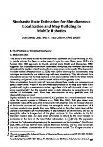
x Fig. 1. Distance and heading measurements.
According to (4)-(6), dynamic estimation of the state vector X(k) can be tackled via Extended Kalman Filter techniques [8, 9], provided that statistical properties of disturbances w(k), vθ (k), vdi (k) and vαi (k) are a priori known or can be reliably estimated. Here, a different approach is taken, which relies on the only hypothesis that the above disturbances are unknownbut-bounded, i.e.
(3)
As the selected landmarks are static ones, the state update equation is X(k + 1) = X(k) + E3 u(k) + E3 G(k)w(k)
(4)
where E3 = [I3 0]0 ∈ R(3+2n)×3 and I3 is the 3 × 3 identity matrix. Several types of measurements can be performed by a vehicle with respect to selected landmarks, depending on the sensors the robot is equipped with. In order to fix the main ideas behind the proposed approach, it is assumed that two sets of measurements are taken by the robot: (i) distance from a landmark; (ii) angle between robot orientation and the direction of a landmark. These measurements can be obtained by several kind of sensors: millimeter-wave radars [8], laser rangefinders [12], stereovision systems [19, 20]. Measurement equations take on the form ∆i (k) = di (X(k)) + vdi (k) (5) Ai (k) = αi (X(k)) + vαi (k) where ∆i (k) and Ai (k) are the actual readings provided by the sensors at time k; vdi (k) and vαi (k) are measurement noises affecting the distance and the heading measurements, respectively. Hence: 4
di (X(k))=d(p(k), Li ) = 4
p
δxi (k)2 + δyi (k)2
αi (X(k))=α(ξ(k), Li ) = atan2 {δyi (k), δxi (k)} − θ(k)
≤ �w (k)
(7)
|vθ (k)| ≤ �vθ (k) |vdi (k)| ≤ �vd (k)
(8) (9)
|vαi (k)| ≤ �vα (k)
(10)
kw(k)k∞
where �w (k), �vθ (k), �vd (k) and �vα (k) are known positive scalars and k · k∞ denotes the `∞ norm (defined as kvk∞ = max vi ). We observe that the above bounds need not i
be the same for different measurements di and αi and for different components of vector w(k) (which is equivalent to consider a weighted `∞ norm). For simplicity of notation, this feature will not be considered in the treatment of the paper, the extension being straightforward. Assumptions (7)-(10) naturally lead to the notion of feasible state vectors. Given sensor readings ∆i (k), Ai (k), i = 1, . . . , n, the feasible states are those compatible with the given measurements, i.e. the states belonging to the measurement set " n # \ M(k) = Mo (k) ∩ Mi (k) , (11) i=1
where Mo (k) = {X : |Θ(k) − θ| ≤ �vθ (k)} , Mi (k) = {X : |∆i (k) − di (X)| ≤ �vd (k) and |Ai (k) − αi (X)| ≤ �vα (k)} .
(6)
with δxi (k) = xLi −x(k), δyi (k) = yLi −y(k) and atan2 {b, a} denoting the four quadrant inverse tangent (see Figure 1). Notice that functions di (·) depend on the robot position only, while functions αi (·) are related to both position and heading.
(12) (13)
A direct consequence is that the dynamic SLAM problem can be formulated in the following set-theoretic form. Set Membership Simultaneous Localization and Mapping Problem (SM-SLAM): Let Ξ(0) ⊂ R3+2n be a set containing the initial vehicle pose and landmarks position X(0). Given
IEEE TRANSACTION ON ROBOTICS AND AUTOMATION - PAPER NO.: H2001-102
the dynamic model (4) and the measurement equations (5)-(6), find at each time k = 1, 2, . . ., the feasible state set Ξ(k|k), which is the set of state vectors X(k) compatible with robot dynamics, assumptions (7)-(10) and measurements collected up to time k. The solution of the SM-SLAM problem is given by the setvalued recursion Ξ(0|0) = Ξ(0), Ξ(k|k − 1) = Ξ(k − 1|k − 1) + E3 u(k − 1)+ E3 G(k − 1)�w (k − 1)B∞ , \ Ξ(k|k) = Ξ(k|k − 1) M(k),
(14)
Assuming robot dynamics ξi (k + 1) = ξi (k) + ui (k) + Gi (k)wi (k) for each agent, the state update equation turns out to be X(k + 1) = X(k) + Em u(k) + Em G(k)w(k)
(18)
where Em = [I3m 0]0 ∈ R(3m+2n)×3m ; G(k) is the blockdiagonal matrix of blocks Gi (k), i = 1, . . . , m; u(k) = 0 [u01 (k) . . . u0m (k)]0 and w(k) = [w10 (k) . . . wm (k)]0 . Absolute proprioceptive sensors will provide the orientation measurements
(15) (16)
where B∞ is the unit ball in the `∞ norm. Algebraic operators in (14)-(16) are to be intended as set operators. Equation (15) exploits the information provided by the robot model and odometric sensors, while in equation (16) all the other measurements are used. Since distance measurements (i.e. ∆i (k) in (5)) are relative measurements, the origin of the reference system can be chosen arbitrarily: without loss of generality, the origin is picked as the robot initial position. Concerning the reference axis for robot orientation, it can be chosen according to the values initially provided by the proprioceptive sensors measuring the robot heading. The main property of recursion (14)-(16) is to provide, at each time step, all the state values that are compatible with all the available information: the true state is guaranteed to belong to the set Ξ(k|k), and the size of this set gives a measure of the quality of the estimates. Unfortunately, exact computation of the sets Ξ in (15)-(16) is generally a prohibitive task, because the measurement set M(k) is the intersection of nonlinear and nonconvex sets. Therefore, set approximations must be pursued. In [15,18], efficient techniques for computing guaranteed outer approximations of the feasible sets have been proposed. The basic idea is as follows: choose a class of simple approximating regions R (e.g. axis-aligned boxes, parallelotopes, ellipsoids, etc.) and select at each time k an element R(k|k) in the class, such that Ξ(k|k) ⊂ R(k|k). The selection of R(k|k) involves a crucial trade-off. On one hand, the “size” of the approximating region (typically, the area of feasible position sets for robot and landmarks) must be minimized in order to reduce conservativeness. On the other side, the computational complexity must be kept small, in order to obtain approximation algorithms suitable for on-line implementation. III. M ULTI - ROBOT SLAM In the previous section, the SM-SLAM problem has been addressed for a single robot, but it seems clear that the set membership approach has a great potential for dealing also with multi-robot systems. In the following, the above formulation will be extended to the case of m robots, whose poses at time k will be denoted by ξ1 (k), . . . , ξm (k), moving in an environment containing n static landmarks L1 , . . . , Ln . The state vector to be estimated becomes 0 X(k) = [ξ10 (k) . . . ξm (k) L01 . . . L0n ]0 ∈ R3m+2n .
3
(17)
Θi (k) = θi (k) + vθi (k), i = 1, . . . , m.
(19)
Since each agent performs measurements with respect to all visible features in the environment (the other robots and the static landmarks), the maximum amount of information provided by exteroceptive sensors is ∆ji (k) = dji (X(k)) + vdj (k) i Aji (k) = αji (X(k)) + vαj (k)
(20)
i
for j = 1, . . . , m, i = 1, . . . , m + n, i 6= j, where ∆ji (k), Aji (k) are the actual readings of the j-th robot sensors towards the i-th feature in the environment (with the notation dji (X) = d(pj , pi ), i = 1, . . . , m and dji+m (X) = d(pj , Li ), i = 1, . . . , n, and similarly for αji ). In the following we will denote by Ωji (k) the pair of measurements ∆ji (k), Aji (k). Similarly to what has been done in the single-robot case, unmodeled dynamics errors and measurement noises are assumed to be unknown-but-bounded, as in (7)-(10). Then, the measurement sets Mj (k), Mjo (k) and Mji (k) associated to Ωji (k), can be defined as in equations (11)-(13) for the single robot case, i.e. "n # \ \ j j j M (k) = Mo (k) Mi (k) (21) i=1
Mjo (k) = {X : |Θj (k) − θj | < �vθ } Mji (k)
= {X : |∆ji (k) − dji (X)| < �vd (k) |Aji (k) − αji (X)| < �vα (k)}.
(22)
and (23)
The exact feasible state set is obtained (at least in principle) through a recursive procedure similar to (14)-(16). Clearly, the exact computation of sets Ξ cannot be tackled in practice. Therefore, an efficient set approximation strategy exploiting the specific structure of the multi-robot SM-SLAM is needed. The main idea is to decompose the approximation of the feasible set Ξ into m + n approximations of 2D feasible subsets for the position of each feature in the environment, plus m interval approximations for the feasible orientation of each robot. Let Rpj and RLh denote outer approximations of the feasible position sets of robot pj and landmark Lh respectively, chosen in the set class R. Moreover, let Roj denote outer approximation of the feasible orientation interval of the j-th robot. The sets defined below will be useful in the following treatment: Mpi (Ωij , Rpj , Roi ): set of positions of robot pi , compatible with uncertainty sets Rpj , Roi and measurements Ωij ;
IEEE TRANSACTION ON ROBOTICS AND AUTOMATION - PAPER NO.: H2001-102
-
-
-
-
-
4
Mpi (Ωih+m , RLh , Roi ): set of positions of robot pi , compatible with uncertainty sets RLh , Roi and measurements Ωih+m ; Mpi (Ωji , Rpj , Roj ): set of positions of robot pi , compatible with uncertainty sets Rpj , Roj and measurements Ωji ; MLh (Ωjh+m , Rpj , Roj ): set of positions of landmark Lh , compatible with uncertainty sets Rpj , Roj and measurements Ωjh+m ; (a) Moi (Ωij , Rpj , Rpi ): set of orientations of robot pi , replacements PSfrag compatible with uncertainty sets Rpj , Rpi and measurements Ωij ; Moi (Ωih+m , RLh , Rpi ) set of orientations of robot pi , compatible with uncertainty sets RLh , Rpi and measurements Ωih+m .
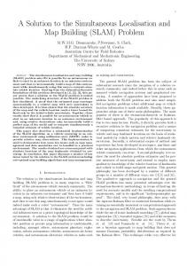
Notice that the first two sets show how the uncertainty on the measured features (robots and landmarks) affects the uncertainty on the robot performing those measurements. More specifically, the set Mpi (Ωij , Rpj , Roi ) is obtained using the measurement that the i-th robot performs on the j-th robot, the latter being considered as a landmark. The shape of this set is defined by uncertainty sets Roi (uncertainty on the orientation of the active robot) and Rpj (uncertainty on the position of the passive robot), together with the uncertainty affecting the measurement. The set Mpi (Ωih+m , RLh , Roi ) enjoys the same properties, but it depends on the uncertainty of the sensed static landmark. On the contrary, the third and fourth sets explain how the uncertainty on the robot performing the measurements affects that of the measured features. More specifically, the set Mpi (Ωji , Rpj , Roj ) gives a description of the uncertainty set of the i-th robot, when it is sensed by the j-th robot. Uncertainty on the active robot position and orientation (sets Rpj and Roj , respectively) together with the measurement uncertainty, define the shape of such set. Concerning the last two sets, they account for robot orientation uncertainty, depending on the measurements performed by the same robot with respect to another agent (the fifth set) or a static landmark (the last set). Notice that in this paper it is assumed that each robot cannot perform measurements on other agents orientation; consequently, information on each robot orientation can be derived only by the measurements performed by the robot itself on other robots and on static landmarks. Nonetheless, it is also possible to include such measurements in the SLAM process (they can be obtained for example by using stereo vision systems). This implies that an additional orientation measurement set would be available, thus giving more refined estimates. For the pair of measurements Ωji considered in this paper, the 2D approximate position sets considered above turn out to be the sum of sectors of circular coronas and the sets Rpj or RLh . In particular, if axis-aligned boxes are used as approximating regions, it is easy to compute the minimum area box containing one of the above sets (see [15] for details). For example, Figure 2 shows how MLh depends on measurements Ωjh+m , robot orientation uncertainty set Roj and robot position uncertainty set Rpj .
E
F
(b) G MLh (Ωjh+m , Rpj , Roj )
R pj (c) Fig. 2.
(d)
Dependence of the set MLh on sets Rpj , Roj and on measure-
ments Ωjh+m . (a) Set E is the feasible landmark set compatible with measurements Ωjh+m , nominal robot position cen(Rpj ) and nominal robot orientation cen(Roj ) (where cen(X ) denotes the center of the set X ); (b) Set F is the feasible landmark set compatible with measurements Ωjh+m , the robot orientation set Roj and nominal robot position cen(Rpj ) (set E is dashed); (c) Set G is the feasible landmark set compatible with nominal measurements Ωjh+m , nominal robot orientation cen(Roj ) and robot position uncertainty set Rpj (dashed); (d) Construction of set MLh (Ωjh+m , Rpj , Roj ) = F + G.
A. Multi-robot SM-SLAM algorithm Let R{S} denote the minimum area set in the class R, containing the set S. Hence, the following recursive approximation strategy provides a solution to the multi-robot SM-SLAM problem. Step 0 (Initialization). Let Rpi (0|0), RLj (0|0) be 2D sets containing the projection of Ξ(0|0) on the subspaces spanned respectively by pi and Lj , i = 1, . . . , m, j = 1, . . . , n. Let Roi (0|0) be the interval obtained projecting Ξ(0|0) on θi , i = 1, . . . , m. For k = 1, 2, . . . repeat the following steps: Step 1. Time update of robot uncertainty sets. For i = 1, . . . , m : Ri+ (k|k − 1) = R {Rpi (k − 1|k − 1) ⊗ Roi (k − 1|k − 1)+ ui (k − 1) + Gi (k − 1)�wi (k − 1)B∞ } (24) where ⊗ denotes Cartesian product between sets. Let Rpi (k|k − 1) be a 2D set in the class R containing the projection of Ri+ (k|k − 1) on the subspace spanned by pi , and Roi (k|k − 1) be the interval obtained projecting Ri+ (k|k − 1) on θi . Step 2. Robot orientation update (based on orientation proprioceptive sensors). For i = 1, . . . , m : b oi (k|k) = Roi (k|k − 1) ∩ Mio (k). R
(25)
IEEE TRANSACTION ON ROBOTICS AND AUTOMATION - PAPER NO.: H2001-102
Step 3. Robot position update (based on measurements performed by the same robot). For i = 1, . . . , m : - let m n o \ b oi (k|k)) (26) A1,i = R Mpi (Ωij (k), Rpj (k|k − 1), R j=1 j6=i
A2,i =
n \
h=1
n R Mpi (Ωih+m (k), RLh (k − 1|k − 1), b oi (k|k)) R
- compute
o n \ \ b pi (k|k) = R Rpi (k|k − 1) A1,i R A2,i .
o
(27)
(28)
The set A1,i contains the feasible set for agent pi based on other robots uncertainty and measurements performed on them by the same agent pi . Set A2,i contains the feasible set for robot pi based on landmarks uncertainty and measurements performed by the same robot. Step 4. Robot position update (based on measurements performed by other robots). For i = 1, . . . , m : - let m n o \ b pj (k|k), R b oj (k|k)) R Mpi (Ωji (k), R (29) A3,i = j=1 j6=i
- compute n o \ b pi (k|k) A3,i . Rpi (k|k) = R R
(30)
Set A3,i contains the feasible position set for robot pi depending on other agents current uncertainty (updated in step 3) and their measurements performed on robot pi . Step 5. Landmark measurement update. For h = 1, . . . , n : - let m o n \ b oj (k|k)) R MLh (Ωjh+m (k), Rpj (k|k), R A4,h =
5
A6,i =
n \
Moi Ωih+m (k), RLh (k|k), Rpi (k|k)
h=1
- compute
b oi (k|k) ∩ A5,i ∩ A6,i . Roi (k|k) = R
�
(34)
(35)
Interval A5,i contains the feasible orientations of the i-th robot, based on other robot uncertainties and measurements performed on them by the i-th agent. Interval A6,i contains the feasible orientations of the i-th robot based on landmarks uncertainty and measurements performed on the landmarks by the i-th robot. It is worth remarking that, no matter which class of approximating sets R is chosen, the above algorithm is conceived so that a guaranteed outer approximation of the true feasible state set Ξ(k|k) is obtained at each k. In fact, it can be easily shown that Ξ(k|k) ⊂ Rp1 (k|k) ⊗ Ro1 (k|k) ⊗ · · · ⊗ Rpm (k|k)⊗ Rom (k|k) ⊗ RL1 (k|k) ⊗ · · · ⊗ RLn (k|k). (36) The only problem remaining is now that of initializing the above recursive procedure. This is a crucial step, because a rough initialization would cause the whole procedure to fail. Indeed, if the initial sets Rpi (0|0), Roi (0|0) and RLj (0|0) are too large (for example, including the whole area in which the robots are moving and all possible robot orientations) the procedure will typically provide no uncertainty reduction. This is a consequence of the simplification introduced by state decomposition, in a context where only relative measurements are available. A natural way to overcome this problem is to exploit the information that each robot is able to acquire by itself in the initialization step. In fact, every agent can solve a single-robot SM-SLAM problem in a preliminary static phase and then provide the estimated map (in its own reference system) to a central unit, possibly located on a leader robot. The unit has to merge all the maps to obtain a unique map in an “absolute” reference system, and then send it to all the agents that will use it to initialize the recursive procedure previously outlined. The problem of merging set-valued maps worked out by different agents will be addressed in Section IV.
j=1
(31)
- compute o n \ RLh (k|k) = R RLh (k − 1|k − 1) A4,h .
(32)
Set A4,h contains the feasible set for landmark Lh based on robots current uncertainty (updated in step 4) and measurements performed by all robots on the landmark Lh itself. Step 6. Robot orientation update (based on measurements performed by the same robot). For i = 1, . . . , m : - let A5,i =
m \
j=1 j6=i
Moi Ωij (k), Rpj (k|k), Rpi (k|k)
�
(33)
B. Computational complexity of the multi-robot SM-SLAM algorithm A nice property of the proposed algorithm for multi-robot SLAM is that the required computational burden is fairly low, and hence suitable for real-time implementation on multi-robot systems. With respect to the number of features present in the environment, the algorithm described in Section III-A performs a fixed number of operations for each measurement pair Ωji (k), i.e. for each feature detected by each measuring agent, at a certain time k. Hence, the complexity at each time step is at most O(m2 + mn). Going into details, it is interesting to analyze the complexity of the multi-robot SM-SLAM algorithm in terms of low level operations that must be performed at each time k. The main
IEEE TRANSACTION ON ROBOTICS AND AUTOMATION - PAPER NO.: H2001-102
computational burden lies in Steps 2 to 6, where the intersection of several feasible sets is tackled, and successive approximations via simple regions in the class R are made. Clearly, an important role is played by the choice of the class R. When axis-aligned boxes are considered, the minimum box approximations R{·} are very easy to compute and the intersections defining sets A in (26),(27),(29),(31) are simple 2D box intersections. More sophisticated set approximations can be considered (e.g., parallelotopes, see [15]) at the price of a slightly higher computational complexity. Steps 2 and 6 concern 1D interval intersections and hence no approximation is involved. Summing up, when using boxes as approximating regions, the most common elementary operation is the computation of the minimum area box containing 2D sets like Mpi or MLh , and the subsequent intersection of such box with another box. If we denote these operations as Elementary Set Updates (ESU), one has that 2m2 + 2mn + n ESUs must be performed at time k (namely, m2 + mn in Step 3, m2 in Step 4 and mn + n in Step 5). Moreover, m2 + mn + m interval intersections are required by Steps 2 and 6. It is worth remarking that in the proposed multi-robot SLAM strategy there is a redundant information management due to the fact that the same measurements are processed several times, in Steps 3 to 6 of the algorithm. This redundancy is useful because, at each step, set approximations are involved and hence measurement reprocessing leads to approximation refinement. In this respect, a further uncertainty reduction can be obtained by repeating iteratively Steps 3-6. If such steps are iterated ρ times, the number of ESUs becomes ρ(2m2 + 2mn + n), while the number of interval intersections grows to ρ(m2 + mn) + m, at each time k. Heuristic strategies can be easily formulated to properly choose the number ρ of iterations, on the basis of a trade-off between computational burden and uncertainty reduction (i.e., SLAM accuracy). IV. M AP FUSION IN THE SET MEMBERSHIP FRAMEWORK In the single robot SLAM problem, the initial position of the exploring agent can be fixed arbitrarily (in the robot centered reference system) and all the environment features are then estimated with respect to that initial position. When operating with multiple agents, the starting position of each robot is not known and cannot be arbitrarily fixed. As long as robot heading is concerned, in the single robot case the absolute orientation sensor provides a heading measurement, which allows one to rotate the initial 2D uncertain map onto an absolute orientation reference system (this amounts to consider Ai (0) + Θ(0) as absolute orientation measurements, corrupted by noise bounded by �vα + �vθ ). Clearly, the same can be done by each agent in the initial step of the multi-robot case. Hence, by computing (or approximating) the initial 2D feasible position sets of each feature, based on measurements Ωji (0) and Θj (0), the j-th agent is able to produce a self-centered initial map of the environment, within an absolute orientation reference system. In other words, only relative translation among the different initial maps produced by the robots is unknown. Clearly, all these single-robot maps are a valid, suboptimal representation of the environment. The quality of the maps
6
will generally vary from robot to robot. While it is possible to choose the “most accurate” map as a global map for all the robots, this choice does not use all the available information. Exploiting the “feasibility” property (i.e., the fact that each setvalued map contains the correct environment representation), it is possible to obtain a global refined map, by finding a description which satisfies all the constraints of each map. This problem is addressed below.
A. One-dimensional map fusion Let us consider axis-aligned boxes as approximating sets R. Exploiting the fact that the initial maps provided by the robots share the same orientation, it is possible to decouple the 2D map fusion into two separate 1D map fusions, which further simplifies computations. Therefore, let us consider m robots and n landmarks spread on a line. Each robot produces its own 1D self-centered map, containing m + n intervals. Let us suppose that intervals in each 1D map are correctly related to the corresponding features. Let us call Cji the center of the set corresponding to the j-th feature in the map, provided by the i-th i i agent. Moreover, let us call Cj− and Cj+ the minimum and maximum value of the interval with center Cji . In terms of relative positions between sets, each ordered map i provides a certain number of constraints, such as i i mj − Mk ≥ Cj− − Ck+ , i i Mj − mk ≤ Cj+ − Ck− .
(37)
for j > k, k ≥ 1, j ≤ m + n, where mj and Mj are respectively the minimum and maximum admissible value for the position of the j-th feature of the map. Note that (37) provides (m + n)(m + n − 1) inequalities in the 2(m + n) unknowns Mk , mk , k = 1, . . . , m + n for each map i. As a general consequence, for m + n ≥ 3, each map provides an overconstrained system, which results to be always feasible. If all the inequalities (37) provided by all maps are considered, one has a system of m(m + n)(m + n − 1) inequalities. Since the SM approach guarantees that each set contains the true feature position, the latter will satisfy all the constraints in (37) for each i. To get the tighter constraints from (37), one can choose as “minimum” distance between set j and k the maximum of all minimum distances (and similarly as “maximum” distance, the minimum of all maximum distances). This leads to mj − Mk = max
i=1,...,m
Mj − m k =
min
i=1,...,m
� i i Cj− − Ck+ , � i i . Cj+ − Ck−
(38)
This time, however, the constraints provided by (38) will not generally be compatible, thus giving an overconstrained, unsolvable linear system. In order to get a solution (Mk , mk ), k = 1, . . . , m + n, it is possible to relax system (38) into a Linear Programming (LP) problem, where each of the equality constraints is transformed into a suitable inequality, while the objective function can be chosen so that the global map uncer-
IEEE TRANSACTION ON ROBOTICS AND AUTOMATION - PAPER NO.: H2001-102
tainty is minimized. This leads to the following LP problem X Mk − m k min mk ,Mk k=1,...,m+n
k=1,...,m+n
subject to the constraints i i mj − Mk ≤ max (Cj− − Ck+ ), j > k; i=1,...,m
Mj − m k ≥
(39)
i i min (Cj+ − Ck− ), j > k;
i=1,...,m
mk − Mk ≤ 0, k = 1, . . . , m + n; m1 = 0. The last equality constraint fixes a point of the map as a common reference for all robots. By solving problem (39), one obtains the maximum and minimum values for the uncertainty interval of each feature, and thus the map (central estimate plus interval width) merging all the information. Notice that the solution of problem (39) provides the minimum uncertainty map (in the sense defined by the chosen cost function) satisfying all the compatible constraints of equations (38), the other constraints being relaxed of the minimum quantity needed to guarantee solvability of the system. B. Dynamic SM-SLAM initialization As stated before, the use of boxes permits to transform the generic 2D map fusion problem into two 1D problems, by considering separately the x and y coordinates. Therefore, a 2D map fusion requires the solution of just two LP problems in the form (39). The resulting map can be used as the initial condition for the dynamic multi-robot SM-SLAM algorithm of Section III-A. In particular, in the Step 0 of the algorithm, the approximate feasible position sets Rpi (0|0), RLj (0|0) are obtained from the 2D map computed via the two LP optimizations, while the intervals [Θi (0) − �vθ (0), Θi (0) + �vθ (0)] can be chosen as feasible orientation intervals Roi (0|0). Then, the time recursion can start, and Steps 1-6 can be repeated for each time instant k. V. S IMULATION
RESULTS
The performances of the proposed multi-robot SLAM strategy have been tested via numerical simulations. More specifically, both static and dynamic simulations have been performed, in order to evaluate separately the map fusion algorithm and the multi-robot SM-SLAM algorithm. A. Static simulations First, a static setting has been considered. In order to quantify the improvement provided by map fusion (performed as in Section IV) over single-robot set-valued maps, several simulations with increasing number of robots (m ≥ 2) and nonsensing distinguishable features (n ≥ 0), randomly spread over a fixed area, have been performed. During these experiments, it was assumed that every robot was able to correctly identify and perform measurements on any other feature present in the environment (i.e., occlusions were not considered). A more realistic scenario will be adopted when performing dynamic simulations (see Section V-B).
7
TABLE I P ERCENTAGE OF MAP UNCERTAINTY REDUCTION ACHIEVED BY
THE MAP
FUSION ALGORITHM : ( A ) WITH RESPECT TO THE AVERAGE UNCERTAINTY OF THE SINGLE - ROBOT MAPS ; ( B ) WITH RESPECT TO THE UNCERTAINTY OF THE BEST SINGLE - ROBOT MAP.
m\n 2 3 4 5 6
0 72.8 74.3 77.3 79.1 80.8
1 63.6 71.2 74.9 77.8 80
2 52.8 67.4 72.4 76.4 78.9
3 46 63.8 70.4 74.8 77.6
4 45.4 64.2 69.2 72.8 76.9
5 43.6 57.7 67.6 72.2 75.8
3 25 36.9 42.4 48.9 53.2
4 21.5 35.1 43.2 46.8 51.4
5 18.7 31.7 39.3 45 48.8
(a) m\n 2 3 4 5 6
0 71.9 54.6 54.3 57.1 57.3
1 44.5 48.6 50.8 52.7 57.1
2 31.6 43.8 47.4 51.5 55.3 (b)
The errors on robot absolute orientation measurements have been neglected (which amounts to consider �vθ ≈ 0), while errors on distance and orientation measurements have been generated as i.u.d. (independent uniformly distributed) signals, satisfying (9) and (10) with constant bounds �vα = 3◦ for the latter, while the bounds on the former depend quadratically on the distance measured, i.e. �vdi (k) = κd d2i (X(k)), with κd = 0.003. This is a standard model for robots using stereovision data to extract landmark information [21]. During the experiments, each agent performs measurements on all the features present in the environment and builds a selfreferenced set-valued map (thus, uncertainty affecting the sensing robot will always be zero in this map). All the maps are then merged, as explained in Section IV, to produce the multi-robot map. The quality of the resulting map is evaluated in terms of the sum of the uncertainty areas of all the features, hereafter denoted as “map uncertainty”. Box approximations have been employed, so that two 1D map fusions are performed, as in Section IV-A. Results are summarized in Tables I-a and I-b, where it is reported the reduction achieved by the multi-robot map uncertainty with respect to the average uncertainty of the single-robot maps (Table I-a) and to the uncertainty of the “best” singlerobot map, i.e. the single-robot map with minimum map uncertainty (Table I-b). Percentages are evaluated over 100 different experiments, for each value of m and n. The result of a typical run of the map fusion algorithm, for the case m = 4, n = 0 is shown in Figures 3 and 4: in Figure 3 the four self-referenced set-valued maps are presented, while the set-valued map produced by the proposed fusion algorithm is reported in Figure 4. Some remarks can be made by inspection of results in Tables I-a and I-b. Uncertainty reduction provided by the map
IEEE TRANSACTION ON ROBOTICS AND AUTOMATION - PAPER NO.: H2001-102
12
8
12
4
10
12
4
10
8
1
8
10 1
6
4
6
4
4
2
2
0
0
8
2
6
2
4
4
4
2 6
6
3
8
2
8
12
10
8
6
4
2
0
2
4
6
8
12
10
2
3
8
6
4
(1)
2
0
2
4
6
8
(2)
12
replacements
1
0
12
10
−2
4
10
4
1
8
8
PSfrag replacements −4
1 6
6
4
4
2
2
0
0
2
2
−6
4
3
−12
2
8 8
6
4
2
0
2
−10
−8
−6
−4
−2
0
2
4
6
8
3
2
6
8 10
3
−8
4
6
12
2
4
(3)
6
8
12
10
8
6
4
2
0
2
4
6
8
Fig. 4. Map provided by the set-valued map fusion algorithm for the four maps of Figure 3.
(4)
Fig. 3. Self referenced set-valued maps produced by each robot, in a scenario with m = 4 and n = 0. All maps have been translated to a common reference system, to facilitate comparison among maps.
fusion algorithm becomes more significant when the number m of robots (and consequently of available maps) increases. This happens because more maps will generally provide overall tighter constraints, in the map fusion step. Notice that such improvement occurs also with respect to the best single-robot map, and therefore it cannot be attributed to a worse quality of some of the single-robot maps. In addition, for a fixed number of robots, improvements get less remarkable as the number n of non-sensing features increases. As a matter of fact, adding non-sensing features to the environment increases the map uncertainty without providing additional means for uncertainty reduction. Also this trend is confirmed by both tables. B. Dynamic simulations Several simulation experiments have been carried out to test the performances of the dynamic multi-robot SM-SLAM algorithm described in Section III. The proposed algorithm has been tested in a setting where four moving agents explore an area where a certain number of distinguishable landmarks is present. In order to take into account some practical problems such as occlusions or the impossibility to perform measurements on far (out-of-field) features, two different sensor models have been employed. 1) Stereovision model: in this scenario, it is assumed that the robots are equipped with an omnidirectional stereo system. Under this assumptions, the expressions for �vα and �vd are those of Section V-A, i.e. �vdi = κd d2i (X(k)) and �vα is constant. In addition, to take into account the limited sensing range, all features that are farther than a fixed distance are considered non detectable, and consequently no measurement is performed on them.
2) Rangefinder model: in this scenario, it is assumed that the robots take measurements on the other features using a rangefinder. Under this assumption, both distance and relative orientation measurements are affected by errors that are almost independent from the actual distance or orientation. This implies that �vα and �vd are constant. However, rangefinders usually provide correct measurement for a limited range of distances and a limited range of relative orientations. To take into account these limitations, each agent can perform measurements only on features that lie within a fixed distance and whose angle between robot orientation and their direction is smaller than a fixed value. Notice that in both scenarios agents are generally not able to perform measurements on all the features present in the environment. This implies that only a subset of the state vector is involved at each time step: nonetheless, the SM-SLAM algorithm presented in Section III operates correctly also under partial information conditions. All the performed tests are carried out in the following setup. Robots move in the unknown environment, covering rough squares. For each agent, disturbance wi (k) on the motion model is generated as a nonstationary i.u.d. signal, with mean value proportional to the distance covered during the last robot move (the longer is the path covered, the bigger are the odometric errors). In Figure 5 a typical simulation run is depicted. For the sake of readability, only two of the four robot trajectories are reported, together with some of the computed robot uncertainty boxes. At the beginning of each experiment, one map fusion is performed after the first exteroceptive measurements at time k = 0. Only features that are perceived by all the agents are considered during this stage. Other features appearing in at least one single-robot map are then added to the common map, exploiting the uncertainty resulting from the map fusion algorithm. Notice that it is only required that one feature is present
IEEE TRANSACTION ON ROBOTICS AND AUTOMATION - PAPER NO.: H2001-102
50 Robot #3
40
4 30
20
3
10
0
−10 1 −20
2
−30 Robot #1 −40
−50
−60
−40
−20
0
20
40
60
Fig. 5. A typical simulation run with four robots: trajectories of two robots (solid and dashed line) and corresponding uncertainty boxes; final uncertainty boxes of the four robots (dashed boxes); landmarks (*) and corresponding final uncertainty boxes.
in all the single-robot maps. Anyway, this is not a restrictive assumption, because each robot can perform a single-robot SLAM, until a common feature is detected by all the robots. After this initialization step, the algorithm presented in Section III-A is run. During the experiments, the odometry error bound on position is set to 10% of the distance covered, the odometry error bound on orientation is equal to 3◦ and the absolute orientation error bound �vθ (affecting the compass) to 2◦ . Two different sets of simulations, for each sensor model, have been carried out. In the first scenario, all the robots are equipped with omnidirectional stereo systems. The uncertainty bound on relative angle measurements is �vα = 3◦ , while the constant for the bound on distance measurements is κd = 0.002. Any feature farther than 50 m can not be detected by the sensor. Ten static landmarks are spread out in a region of about 104 m2 . In the second scenario, all the robots are equipped with rangefinders. The uncertainty bound on relative angle measurements is �vα = 3◦ , while the bound on distance measurements is �vd = 0.05 m. Any feature farther than 30 m, or with a relative angular distance greater than 90◦ is not detected by the sensor. Eight static landmarks are spread out in a region of about 1600 m2 . Figures 6, 7 and 8 compare the results provided by the multirobot SLAM approach to those of the single-robot algorithm, in the first scenario. Results are averaged over 300 experiments. Figure 6 shows the average area of the four robot uncertainty boxes, computed by each agent via the single-robot SM-SLAM (dashed lines) and by applying the proposed multi-robot SLAM algorithm (solid line). In the single-robot case, the average at time k is made over the number of robots detected up to time k (see bottom of Figure 6). Since in the single-robot case only one agent performs measurements on the environment, while in the multi-robot case all the robots are active, the average uncertainty is dramatically reduced by the multi-robot approach. This happens mainly because the uncertainty of the non sensing robots tends to increase (i.e., such robots “get lost” after some time). More significantly, Figure 7 reports the uncertainty af-
9
fecting the active agent in one of the single-robot SLAM runs, compared with the uncertainty of the same robot in the multirobot run. The initial gap between the two plots is due to the fact that in the single-robot case the reference system of the active robot is assumed known, while for the multi-robot case an initial map fusion is needed. Nevertheless, it can be observed that the remarkable uncertainty growth due to the fact that the robot moves far away from its initial position, disappears when the multi-robot strategy is adopted. This means that the robot is able to precisely localize itself also at large distances from its starting point, thanks to the fact that the other agents have constructed a good map of initially faraway areas, by reducing the uncertainty affecting landmark positions. In Figure 8 the average area of uncertainty boxes for the detected landmarks is reported. Once again, it can be seen the clear improvement provided by the multi-robot SLAM technique. Analogous results, in the case of robots equipped with rangefinder-like sensors, are reported in Figures 9, 10 and 11. With this kind of sensor model (and due to the trajectory followed by each agent, see Figure 5), the uncertainty area of a robot exhibits the typical periodic behavior depicted in Figure 10, both in the single-robot and in the multi-robot case. This is due to the limited field of view of the sensor, that allows a robot to detect only a small subset of features, especially in the parts of the trajectory in which the robot points “outside” the environment. Notice how the higher precision of the sensor results in a relatively less significant improvement of the multirobot SLAM with respect to the single robot case, especially in terms of uncertainty of the sensing agent (Figure 10). Nevertheless, the advantage in the construction of the map is still remarkable (see Figure 11). VI. C ONCLUSIONS AND FUTURE DEVELOPMENTS A set membership approach to the problem of simultaneous localization and mapping for a team of mobile robots has been proposed. Simulation results demonstrate that the improvement of multi-robot SLAM with respect to the single-robot case is remarkable, both for static map fusion and for dynamic localization and map updating. The computational burden of the proposed algorithm is fairly low, because set approximations are based on recursive intersections of simple 2D sets (e.g. boxes). Future investigations may concern the challenging problem of multi-robot localization and mapping for a team of indistinguishable agents. This requires a preliminary matching stage, in which the features detected by each robot in its own map are correctly associated to the corresponding features in the other maps. Open problems are how to exploit set-valued maps in order to exclude unfeasible matchings or detect possible ambiguities, as well as the formulation of efficient algorithms that can tackle the matching problem with a reasonable computational effort. Another important open issue is that of multi-robot motion planning in a set membership setting. The main objective in this case is to use the set-valued uncertainty representation in order to design trajectories of the robots according to some meaningful performance indices. For example, one may want to minimize the overall map uncertainty, when exploring unknown en-
IEEE TRANSACTION ON ROBOTICS AND AUTOMATION - PAPER NO.: H2001-102
10
200
30 25 20
Area (m2 )
Area (m2 )
150
100
50
15 10 5
0
0
10
20
30
40
50
60
70
80
90
0
0
10
20
30
40
Time
50
60
70
80
90
50
60
70
80
90
Time
4
4
PSfrag replacements
3
n◦ of detected robots
rag replacements
n◦ of detected robots
3.5
2.5 2 1.5 1
0
10
20
30
40
50
60
70
80
90
Time
3.5 3 2.5 2 1.5
0
10
20
30
40
Time
Fig. 6. Comparison of single-robot (dashed lines) and multi-robot (solid line) SM-SLAM: average robot uncertainty (top) and average number of detected robots up to current time (bottom). Results are averaged over 300 experiments. Simulations are carried out using the stereovision system sensor model.
Fig. 9. Comparison of single-robot (dashed lines) and multi-robot (solid line) SM-SLAM: average robot uncertainty (top) and average number of detected robots up to current time (bottom). Results are averaged over 300 experiments. Simulations are carried out using the rangefinder sensor model.
50 3.5
45
40
3
35 2.5
rag replacements
25
2
Area (m2 )
Area (m2 )
30
20
1.5
15
PSfrag replacements
10
1
5 0.5
n◦ of detected robots
0
0
10
20
30
40
50
60
70
80
90
Time
n◦ of detected robots
Fig. 7. Comparison of single-robot (dashed lines) and multi-robot (solid line) SM-SLAM: uncertainty of one active (sensing) robot. Results are averaged over 300 experiments. Simulations are carried out using the stereovision system sensor model.
0
0
10
20
30
40
50
60
70
80
90
Time
Fig. 10. Comparison of single-robot (dashed lines) and multi-robot (solid line) SM-SLAM: uncertainty of one active (sensing) robot. Results are averaged over 300 experiments. Simulations are carried out using the rangefinder sensor model.
80
5 4
40
Area (m2 )
Area (m2 )
60
20
0
3 2 1
0
10
20
30
40
50
60
70
80
90 0
Time
0
10
20
30
40
50
60
70
80
90
50
60
70
80
90
Time
10
rag replacements
8
7
6
0
10
20
30
40
50
60
70
80
90
Time
Fig. 8. Comparison of single-robot (dashed lines) and multi-robot (solid line) SM-SLAM: average landmark uncertainty (top); average number of detected landmarks up to current time (bottom). Results are averaged over 300 experiments. Simulations are carried out using the stereovision system sensor model.
n◦ of detected landmarks
n◦ of detected landmarks
8
PSfrag replacements
9
7.5
7
6.5
0
10
20
30
40
Time
Fig. 11. Comparison of single-robot (dashed lines) and multi-robot (solid line) SM-SLAM: average landmark uncertainty (top); average number of detected landmarks up to current time (bottom). Results are averaged over 300 experiments. Simulations are carried out using the rangefinder sensor model.
IEEE TRANSACTION ON ROBOTICS AND AUTOMATION - PAPER NO.: H2001-102
vironments, or alternatively to reduce the average robot uncertainty during the accomplishment of a prescribed task, such as a coordinated action or the transfer from an assigned configuration of the multi-robot system to another.
R EFERENCES [1] I. J. Cox and G. T. Wilfong (Eds.). Autonomous Robot Vehicles. Springer Verlag, 1990. [2] J. J. Leonard and H. F. Durrant-Whyte. Directed Sonar Sensing for Mobile Robot Navigation. Kluwer Academic Publisher, Boston, 1992. [3] J. Borenstein, B. Everett, and L. Feng. Navigating Mobile Robots: Systems and Techniques. Wellesley: AK Peters, 1996. [4] S. Lacroix, A. Mallet, R. Chatila, and L. Gallo. Rover self localization in planetary-like environments. In 5th International Symposium on Artificial Intelligence, Robotics and Automation in Space, June 1999. [5] C. F. Olson. Probabilistic self-localization for mobile robots. IEEE Transactions on Robotics and Automation, 16(1):55–66, 2000. [6] J. A. Castellanos, J. M. Martinez, J. Neira, and J. D. Tardos. Simultaneous map building and localization for mobile robots: A multisensor fusion approach. In Proc. IEEE Int. Conf. Robotics and Automation, pages 1244–1249, Leuven, Belgium, May 1998. [7] S. Thrun, W. Burgard, and D. Fox. A probabilistic approach to concurrent mapping and localization for mobile robots. Machine Learning, 31:29-53 and Autonomous Robots, 5:253-271, 1998. Joint issue. [8] M.W.M.G. Dissanayake, P. Newman, S. Clark, H.F. Durrant-Whyte, and M. Csorba. A solution to the simultaneous localization and map building (SLAM) problem. IEEE Transactions Robotics and Automation, 17(3):229–241, 2001. [9] J. J. Leonard and H. J. S. Feder. A computationally efficient method for large scale concurrent mapping and localization. In J. Hollerbach and D. Koditscheck, editors, Robotic Research: the Ninth International Symposium. Springer-Verlag, 2000. [10] R. C. Arkin and G. A. Bekey (Eds.). Special issue on Robot Colonies. Autonomous Robots, 4(1), 1997. [11] T. Balch and L. E. Parker (Eds.). Special issue on Heterogeneous Multirobot Systems. Autonomous Robots, 8(3), 2000. [12] R. Grabowski, L. E. Navarro-Serment, C. J. J. Paredis, and P. K. Khosla. Heterogeneous teams of modular robots for mapping and exploration. Autonomous Robots, 8(3):293–308, 2000. [13] S. I. Roumeliotis and G. A. Bekey. Collective localization: A distributed Kalman filter approach to localization of groups of mobile robots. In Proc. IEEE Int. Conf. Robotics and Automation, pages 2958–2965, San Francisco, CA, April 2000. [14] D. Fox, W. Burgard, H. Kruppa, and S. Thrun. A probabilistic approach to collaborative multi-robot localization. Autonomous Robots, 8(3):325– 344, 2000. [15] M. Di Marco, A. Garulli, S. Lacroix, and A. Vicino. Set membership localization and mapping for autonomous navigation. International Journal of Robust and Nonlinear Control, 11(7):709–734, 2001. [16] M. Milanese and A. Vicino. Optimal estimation theory for dynamic systems with set membership uncertainty: an overview. Automatica, 27(6):997–1009, 1991. [17] M. Milanese, J. P. Norton, H. Piet-Lahanier, and E. Walter, editors. Bounding Approaches to System Identification. Plenum Press, New York, 1996. [18] A. Garulli and A. Vicino. Set membership localization of mobile robots via angle measurements. IEEE Transactions on Robotics and Automation, 17(4):450–463, August 2001. [19] C. Drocourt, L. Delahoche, C. Pegard, and A. Clerentin. Mobile robot localization based on an omnidirectional stereoscopic vision perception system. In Proc. IEEE Int. Conf. Robotics and Automation, pages 1329– 1334, Detriot, USA, 1999. [20] S. Lacroix, A. Mallet, D. Bonnafous, S. Fleury, M. Di Marco, and R. Chatila. Autonomous long range navigation in planetary-like environments. In 6th ESA Workshop on Advanced Space Technologies for Robotics and Automation (ASTRA 2000), Noordwijk, The Nederlands, December 2000. [21] Y. Xiong and L. Matthies. Error analysis of a real time stereo system. In IEEE Conference on Computer Vision and Pattern Recognition, pages 1087–1093, Puerto Rico, June 1997.
11
Mauro Di Marco was born in Firenze, Italy, in 1970. He received the Laurea Degree in Electronic Engineering from the Universit`a di Firenze, Firenze, Italy and the Ph.D. degree in System Engineering from the Universit`a di Bologna, Bologna, Italy, in 1997 and 2001, respectively. Since 2000 he has been with the Universit`a di Siena, Siena, Italy, where he is currently Assistant Professor of Circuit Theory. From November 1999 to April 2000 he held a visiting position at LAAS, Toulouse, France. His main research interests are in analysis of nonlinear dynamics of complex systems and neural networks, in robust estimation and filtering, and in autonomous navigation. Andrea Garulli was born in Bologna, Italy, in 1968. He received the Laurea in Electronic Engineering from the Universit`a di Firenze in 1993, and the Ph.D. in System Engineering from the Universit`a di Bologna in 1997. In 1996 he joined the Dipartimento di Ingegneria dell’Informazione of the Universit`a di Siena, where he is currently Associate Professor. He is Associate Editor of the IEEE Transactions on Automatic Control and member of the Conference Editorial Board of the IEEE Control Systems Society. He is author of more than 60 technical publications and co-editor of the book ”Robustness in Identification and Control”, Springer, 1999. His present research interests include system identification, robust estimation and filtering, mobile robotics and autonomous navigation. Antonio Giannitrapani was born in Salerno, Italy, in 1975. He received the Laurea degree in Computer Engineering from the Universit`a di Siena in 2000. He is currently a Ph.D. student at the Dipartimento di Ingegneria dell’Informazione of the Universit`a di Siena. His current research interests include the application of advanced estimation techniques to mobile robotics and autonomous navigation.
Antonio Vicino was born in 1954. He received the Laurea in Electrical Engineering from the Politecnico di Torino, Torino, Italy, in 1978. From 1979 to 1982 he held several Fellowships at the Dipartimento di Automatica e Informatica of the Politecnico di Torino. He was assistant professor of Automatic Control from 1983 to 1987 at the same Department. From 1987 to 1990 he was Associate Professor of Control Systems at the Universit`a di Firenze. In 1990 he joined the Dipartimento di Ingegneria Elettrica, Universit`a di L’Aquila, as Professor of Control Systems. Since 1993 he is with the Universit`a di Siena, where he founded the Dipartimento di Ingegneria dell’Informazione and covered the position of Head of the Department from 1996 to 1999. From 1999 he is Dean of the Engineering Faculty. In 2000 he founded the Center for Complex Systems Studies (CSC) of the University of Siena, where he presently covers the position of Director. He has served as Associate Editor for the IEEE Transactions on Automatic Control from 1992 to 1996. Presently he serves as Associate Editor for Automatica and Associate Editor at Large for the IEEE Transactions on Automatic Control. He is Fellow of the IEEE. He is author of 170 technical publications, co-editor of 2 books on ‘Robustness in Identification and Control’, Guest Editor of the Special Issue ‘Robustness in Identification and Control’ of the Int. Journal of Robust and Nonlinear Control . He has worked on stability analysis of nonlinear systems and time series analysis and prediction. Presently, his main research interests include robust control of uncertain systems, robust identification and filtering, mobile robotics and applied system modelling.