May 3, 2017 - mation bits are usually stored; therefore, the search for other ..... [4] K. Y. Guslienko, X. F. Han, D. J. Keavney, R. Divan, S. D. Bader, Mag-.
Single array of magnetic vortex disks uses in-plane anisotropy to create different logic gates H. Vigo-Cotrina Centro Brasileiro de Pesquisas F´ısicas, 22290-180, Rio de Janeiro, RJ, Brazil
arXiv:1705.01232v1 [cond-mat.mes-hall] 3 May 2017
A.P. Guimar˜aes Centro Brasileiro de Pesquisas F´ısicas, 22290-180, Rio de Janeiro, RJ, Brazil
Abstract Using micromagnetic simulation, we show that in-plane uniaxial magnetic anisotropy (IPUA) can be used to obtain FAN-OUT, AND and OR gates in an array of coupled disks with magnetic vortex configuration. First, we studied the influence of the direction of application of the IPUA on the energy transfer time (τ) between two identical coupled nanodisks. We found that when the direction of the IPUA is along the x axis the magnetic interaction increases, allowing shorter values of τ, while the IPUA along the y direction has the opposite effect. The magnetic interactions between the nanodisks along x and y directions (the coupling integrals) as a function of the uniaxial anisotropy constant (Kσ ) were obtained using a simple dipolar model. Next, we demonstrated that choosing a suitable direction of application of the IPUA, it is possible to create several different logic gates with a single array of coupled nanodisks. Keywords: Magnetic vortex, Thiele’s equation, uniaxial anisotropy, coupling integrals, logic gates
1. Introduction The magnetic vortex configuration is a ground state characterized by a curling magnetization in the plane, and a small region (core vortex) in the center, where of magnetization is out the plane [1, 2]. From these characteristics, two properties are defined: the circulation C and the polarity p. The circulation is C = +1 when the curling direction is counterclockwise (CCW) and C = -1 when it is clockwise (CW). The polarity is p = +1 when the core points in the +z direction and p = -1 in the -z direction. The magnetic vortex dynamics is characterized by an eigenfrequency (gyrotropic frequency) in the sub-gigahertz range [1–4]. This frequency depends on the intrinsic parameters of the material and on the ratio β of the thickness to the radius of the disk (β = L/R) [1]. The use of the magnetic vortices in logic gates is one of the potential technological applications in spintronics [5–8]. Controlling parameters such as the polarity and circulation, different logical configurations can be obtained, as already demonstrated by Jung et al. [5], and controlling the magnetic interaction through the separation distance between the disks, it is possible to perform fan-out operations [7]. Therefore, the control of these parameters is of vital importance for the construction of logic gates. Both p as C can be controlled with rotating magnetic fields [5, 9], and the magnetic interaction can be modified without the need to change the separation distance between the disks. One of the ways of obtaining this goal is by the application of perpendicular magnetic fields (PMF) to the plane of the disks Preprint submitted to Elsevier
[10]. This method may not be very effective, since the PMF distorts the core profile of the vortex, which is where the information bits are usually stored; therefore, the search for other mechanisms is an open topic. In this sense, the influence of the in-plane uniaxial anisotropy (IPUA) on the dynamics of magnetic vortices is gaining interest in recent years [11, 12]. Experimentally, the IPUA can be induced by voltage-induced strain via a piezoelectric transducer (PZT) [12, 13]. The advantage of using the IPUA, is that this does not alter the core profile of the vortex, making it a practical tool to control the dynamics of the magnetic vortex [11, 12]. When disks with magnetic vortex configuration are coupled, energy is transfered periodically between them [14]. The energy transfer is characterized by an energy transfer time parameter τ. Therefore, controlling this parameter is very important to affect this transfer. In a previous work, we have shown that applying the IPUA along the x axis allows obtaining shorter energy transfer times [12]. The goal of this work is to study the influence of changing the direction of application of the IPUA in a pair of identical nanodisks, and using the IPUA in order to obtain different logical configurations with an array of coupled nanodisks. We used micromagnetic simulations and a simple analytical dipolar model in order to obtain the interactions along the x and y directions (the coupling integrals). We used the open source software Mumax [15], with cell size of 2 × 2 × 7 nm3 ; the magnetostrictive material used was Galfenol (FeGa) with parameters [16, 17]: saturation magnetization M s = 1.360 × 10⁶ A/m2 , exchange stiffness A = 14 × 10−12 J/m and a typical damping constant May 4, 2017
α = 0.01. The anisotropy constant (Kσ ) varied from 0 to 58500 J/m3 . The magnetoelastic energy was included in the micromagnetic simulation as an uniaxial anisotropy energy [11, 12].
of using IPUA as a tool for the control of the energy transfer time, as we have already demonstrated in our previous work [12]. Now, for IPUA-y and a reduced distance d = 2.11, τ increases approximately 140%, from τ = 17.3 ns (Kσ = 0 kJ/m3 ) to τ = 42 ns (Kσ = 19.5 kJ/m3) for the case p = +1, and an increase of approximately 48%, from τ = 7.5 ns (Kσ = 0 kJ/m3 ) to τ = 11.2 ns (Kσ = 58.5 kJ/m3), for the p = -1 case. In every case, the values of τ were obtained from the temporal dependence of the energy density of each disk, considering that τ is the time in which the energy of disk 1 reaches the minimum value for the first time [14].
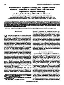
2. Results and discussion 2.1. Two coupled disks 2.1.1. Micromagnetic simulation We considered a system of two coupled identical disks, located along the x-axis, with thickness L = 7 nm, diameters 256 nm, and separated by a center to center distance D (Fig. 1). In order to induce gyrotropic motion we have applied an inplane static magnetic field in the x direction for a few nanoseconds, only on disk 1 to displace the vortex core from the equilibrium position (center of the disk), and using a large damping α = 1 for faster convergence. Then this field was removed and the IPUA was applied to both disks, a typical value of α = 0.01 was used, allowing the vortex core to perform the gyrotropic motion. The movement of the vortex core in the disk 2 is induced by the transfer of energy from disk 1. This process is repeated for each value of Kσ . Unlike our previous work, we have also considered the case when the uniaxial anisotropy is in the direction of the y axis. The values of τ depending on the Kσ are shown in Fig. 2. This dependence of τ with Kσ is the opposite of that obtained in our previous work, where the direction of the IPUA was applied along the x-axis [12].
11
x direction
40
y direction
9 p = +1
20
(ns)
(ns)
d = 2.11
d = 2.11
8
p = -1
7 6
10
5
a)
0
10
20 K
30
40
50
60
b)
0
10
3
(kJ/m )
14
x direction y direction
50
20 K
60
30
40
50
60
3
(kJ/m )
x direction y direction
13 12
d = 2.23
30
p = +1
(ns)
40 (ns)
y direction
10
30
11 d = 2.23
10
p = -1
9
20 10
x direction
8 7
c)
0
10
20 K
30
40 3
(kJ/m )
50
60
d)
0
10
20 K
30
40
50
60
3
(kJ/m )
Figure 2: Variation of τ with respect to Kσ for a reduced distance d = D/R = 2.11 (a-b) and d = D/R = 2.33 (c-d) for the cases p = +1 and p = -1
As can be seen in Fig. 2, we have considered only three values of Kσ (0, 9.75 and 19.5 kJ/m3) for IPUA-y, d = D/R = 2.11, and p = +1, For larger values of Kσ , a simple free induction decay (FID), with a decay time of approximately 100 ns and the same gyrotropic frequency (thus there is no frequency splitting), is observed in both disks. This means that the energy of disk 1 is fully transferred to disk 2 for a value of τ comparable to the decay time of the FID. During this stage, the vortex core of disk 2 performs a gyrotropic motion of negligible amplitude. The initial amplitude of the FID in disk 1 is due to the initial displacement of the vortex core by the application of the inplane magnetic field. During this stage, although no magnetic field is applied in disk 2, the vortex core is also displaced due to the magnetic interaction between the disks [18]. This interaction is due to the presence of surface and/or volume charges in disk 1 resulting from the displacement of the vortex core by the application of the in-plane magnetic field [18, 19]. The displacement in disk 2 is negligible in comparison to the displacement in disk 1, and is of the order of 15 nm. For IPUA-y and p = -1, we have used 58.5 kJ/m3 as the maximum value of Kσ ,
Figure 1: Coupled nanodisks with magnetic vortex configuration separated by a center-to-center distance D; d = D/R is the reduced distance. The vortex core of disk 1 was displaced by an in plane static magnetic field µ0 H = 20 mT in the +x direction. This is the typical initial configuration used to perform the study of the energy transfer time between two disks.
When the direction of application of the IPUA is along the y axis (IPUA-y), the values of τ increase, while when the direction is along the x axis (IPUA-x), τ decreases. For example, considering IPUA-x, for the case p = p1 .p2 = +1 and a reduced distance d = D/R = 2.11, τ is reduced by approximately 66% from τ = 17.3 ns (Kσ = 0 kJ/m3) to τ = 5.8 ns (Kσ = 58.5 kJ/m3) and for the case p = -1, τ is reduced approximately by 40% from τ = 7.5 ns (Kσ = 0 kJ/m3 ) to τ = 4.6 ns (Kσ = 58.5 kJ/m3). This reduction in the τ values is appreciable and show the efficiency 2
as already mentioned in section 1. For larger values of Kσ , the magnetic vortex configuration is not stable. The reason why it is still observed an energy transfer, even using our maximum allowed value of Kσ , is because the magnetic interaction between the disks is stronger in comparison with the case p = +1, therefore, high values of Kσ are required to decrease the magnetic interaction between the disks.
p ω1,2
Eigenfrequencies (GHz)
0.46
0.46
0.44
0.44
0.42
0.40
0.38
p = +1 0.36 2.0
∗
ηx = η
ηy = −2η ,
8π η x,y , µ0 RM 2s
(2)
dX ∂W(X) − =0 dt ∂X
0.42
0.40
0.38
p = -1
2.1
2.2
2.3
2.4
2.0
2.1
2.2
2.3
2.4
d
Figure 3: Variation of eigenfrequencies f1,2 with the reduced distance d = D/R between two disks, for the cases p = p1 .p2 = +1 and p = p1 .p2 = -1, and considering Kσ = 9.75 kJ/m3 (IPUA-x). The blue triangles represent the values obtained from micromagnetic simulations, and the red solid line represents the values obtained from the simultaneous fit using Eq. (6) and Eq. (7).
(3)
where η∗ = µ0 λ2 M 2s L2 R2 /4πD3 . The λ parameter, which takes into account the influence of Kσ , can be obtained from a simultaneous fit of the coupling frequencies f1,2 = ω1,2 /2π (or eigenfrequencies) as has already been demonstrated by Asmat et al. [22]. In order to obtain this parameter, we used the Thiele’s equation [23]. Considering a negligible damping, this equation can be written as: G×
(5)
0.36
d
or in their dimensionless forms: I x,y =
η∗ 2 η∗ p ) ± ω0 5 − 4p, G G
Eigenfrequencies (GHz)
(1)
where η x and ηy are the interactions between the disks along x and y directions (the coupling integrals), C1 and C2 are the circulations in disk 1 and disk 2, and Xi = (xi , yi ), with i = 1,2 is the vector position of the vortex core of the disks. The coupling integrals can be expressed as a sum of contributions of high order magnetic interactions, such as dipoleoctupole, octupole-octupole, dipole-triacontadipole, etc. [21]. However, in our model we only consider purely dipole interaction since this is sufficient to explain the influence of IPUA on the magnetic interactions, as we demonstrated in our previous work [12]. Thus, within our dipolar model, the coupling integrals are defined as follows: ∗
ω20 − 2p(
with ω0 = 2π f0 , where f0 is the gyrotropic frequency for an isolated disk. Replacing the expressions for G, κ, f0 and η∗ in Eq. 5, we have: r λ2 λ4 p=+1 (6) f1,2 = f0 1 − 0.0103 6 ± 0.0718 3 d d r λ4 λ2 p=−1 f1,2 = f0 1 − 0.0103 6 ± 0.2154 3 (7) d d Eq. (6) and Eq. (7) are the analytical expressions for the coupling frequencies (f1 and f2 are the high (+) and low (-) frequencies) within the dipolar approximation for p = p1 .p2 = +1 and p = p1 .p2 = -1, respectively. The dependence of the eigenfrequencies on reduced distance d = D/R is shown in Fig. 3 for Kσ = 9.75 kJ/m3 and IPUA-x.
2.1.2. Analytical dipolar model In order to clarify the physical meaning of the influence of the IPUA on the magnetic interactions, we used a simple dipolar model, also used in our previous work [12]. The magnetic interaction energy (Wint ) between two disks with magnetic vortex configuration is given by [20]: Wint = C1C2 (η x x1 x2 + ηy y1 y2 ),
=
r
The values of lambda were obtained from the simultaneous fits to the results shown in Fig. 3. A value of λ = 2.77 is obtained for Kσ = 9.75 kJ/m3. The same procedure is done for each value of Kσ . We obtained an increases of the λ parameter, from λ = 2.59 (Kσ = 0 kJ/m3 ) to λ = 3.79 (Kσ = 58.5 kJ/m3) for IPUA-x. For IPUA-y 1 we obtained a decrease of the λ parameter, from λ = 2.59 (Kσ = 0 kJ/m3 ) to λ = 2.32 (Kσ = 58.5 kJ/m3). There are discrepancies between the values obtained from micromagnetic simulation and the fit using Eq. (6). This is expected, since our model considers only dipolar interaction, without consider high-order magnetic interactions as dipole-octupole, octupoleoctupole, dipole-triacontadipole, which are important for small separation distances [12, 21]. However, the fit is well-behaved when the separation distance between the disks is larger [12]. The dependence of the coupling integral η x on Kσ and the
(4)
where G is the gyrovector G = -Gpˆz, G = 2πµ0 LM s /γ is the gyrotropic constant, and γ = 2.21×10⁵ m/As is the gyromagnetic ratio; W(X) = W(0) + 21 κX2 is the potential energy and κ = 40πM2s L2 /9R is the stiffness coefficient calculated within the side-charge-free model at L/R