Abstract. The use of a single camera and rotating mirror for depth estimation in a periscope-like system is examined. It is found that such an arrange-.
Single-Camera Computational Stereo Using a Rotating Mirror A. F. Clark and S. W. Chan Image Processing Group Department of Electronic Systems Engineering University of Essex Wivenhoe Park, Colchester C04 3SQ, UK alienQessex.ac.uk Abstract The use of a single camera and rotating mirror for depth estimation in a periscope-like system is examined. It is found that such an arrangement is viable and that the problem of matching features in successive frames may be greatly simplified by comparatively straightforward pre-processing. Experimental results are presented and some possible applications of such a compact stereo sensor are outlined.
1
Introduction
Depth perception is one of the more important functions of the human visual system. Although several cues are involved — shading, relative size, etc. — stereo plays a crucial role. Computational stereo, now in widespread use in computer vision, naturally mimics the human visual system by having two cameras viewing the 3-D scene [2]. In recent years, single-camera approaches to computational stereo have become of interest: the simplest of these merely replace the two cameras with a mirror system [8] or glass plate [7], though more recent work has employed inclined mirrors [3]. Such arrangements suffer from two disadvantages: they have a limited field of view and, in order to produce an acceptable baseline, must be physically big. There are a number of vision tasks in which the physical size of the sensor limits its usage: examples of this are the inspection of the insides of aircraft engines and medical endoscopy. In such cases, physical size and a panoramic field of view are both important factors. Both of these may be met by employing the principle of the periscope in computational stereo. This is the purpose of this paper — "periscopic stereo." The periscope has, of course, been used for viewing in awkward configurations for many, many years, though its potential for computational stereo does not appear to have been exploited in vision systems. Panoramic cameras, as found in remote sensing, and linescan imagers (used in military aircraft) have essentially the same imaging geometry [9]. A conical mirror, which also features a similar geometry, has been used for panoramic stereo [10], though two viewpoints were
762
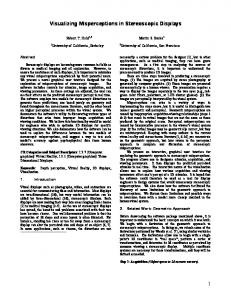
image plane
lens
mirror rotating about z
Figure 1: Schematic Diagram of Mirror Arrangement still employed. The fact that rotation may be used as the basis of a stereo viewing geometry was first reported widely in [4]. Subsequent work [6] replaced the rotating camera with a rotating mirror, analyzing the case in which the axis of rotation of the mirror is perpendicular to the optical axis of the camera and reported simulation, though not experimental, results. The same paper also gave a preliminary analysis of the case considered here, in which the axis of rotation of the mirror lies along the optical axis (Figure 1). This paper gives a detailed analysis of the periscopic geometry. It indicates how, with a suitably calibrated system, the problem may be reduced to an essentially one-dimensional one. Experimental results with a prototype system are presented and some potential applications are briefly considered.
2
Camera Motion in Rotating Systems
The basic arrangement of the system is shown in Figure 2. Light from the scene is reflected by a mirror positioned at the origin and inclined at an angle 9 onto a camera whose lens is centred at the point
763 real camera
Figure 2: Side Elevation of Optical System
C=
(1)
i.e., the camera is placed a distance C away from the mirror along the ar-axis. (The notation and the general approach to the analysis are similar to those of [6].) The mirror is made to rotate about the x-axis by an angle . We proceed by considering a 'virtual' camera: this occupies a position equivalent to the real camera but 'behind' the mirror; i.e., it is the position at which the real camera would have to be located if the mirror were not present. From Figure 2, we observe that the surface normal, n, is given by
(
cosf? \ sinflsin^ I .
(2)
sin 0 cos I In order to find the location of the virtual camera, C_v, we first consider the perpendicular projection of the real camera position onto the mirror plane (see Figure 2): Cm=C-
ah.
(3)
(C + 6x) - (2 sin 2 9 sin 2 - \)8y - 2 sin 2 9 sin cos 6z — sin 29 cos (C + Sx) — 2 sin 2 9 sin cos