SINGLE-PASS MULTI-VIEW VOLUME RENDERING Thomas Hübner Visualization and MultiMedia Lab, Department of Informatics, University of Zurich Binzmühlestrasse 14, CH-8050 Zürich
[email protected]
Renato Pajarola Visualization and MultiMedia Lab, Department of Informatics, University of Zurich Binzmühlestrasse 14, CH-8050 Zürich
[email protected]
ABSTRACT In this paper, we introduce a new direct volume rendering (DVR) algorithm for multi-view auto-stereoscopic displays. Common multi-view methods perform multi-pass rendering (one pass for each view) and subsequent image compositing and masking for generating multiple views. The rendering time increases therefore linearly with the number of views, but sufficient frame-rates are achieved by sub-resolution rendering, at the expense of degraded image quality. To overcome these disadvantages for DVR, our algorithm calculates multiple views directly on a per-fragment basis on the GPU in a single rendering pass, including sub-pixel wavelength selective views for high-quality auto-stereo display systems. Moreover, our approach retains full resolution rendering, preserving best possible image quality, while achieving higher frame rates than present multi-view rendering methods. We describe our multi-view volume rendering algorithm and its implementation using programmable fragment shaders. Experimental results demonstrate our algorithm's improvement compared to prior multi-view volume rendering solutions. KEYWORDS Multi-View Volume Rendering, Auto-Stereo Volume Visualization, Three-Dimensional Displays
1. INTRODUCTION Research in volume visualization [Brodlie and Wood 2001], particularly texture-based volume rendering, has largely focused on challenging issues in the field such as handling large data [Kniss et al 2001, Schneider and Westermann 2003], improving quality of rendering [Engel et al 2001, Lum 2004] and increasing rendering efficiency [Boada et al 2001, Schneider and Westermann 2003]. The rapid development of graphics hardware and in particular the integration of highly programmable GPUs made it possible that volumes can be visualized today at interactive frame-rates and with high visual fidelity. Multi-view auto-stereoscopic display systems [Dodgson 2005] provide greatly enhanced spatial understanding of 3D data through perceptual cues for stereo and motion parallax. However, despite that autostereoscopic displays are becoming a common technology, spatial visualization has received far less attention in the field. In multi-view display systems, the rendering time is the limiting factor, as, compared to singleview displays, multiple images have to be rendered simultaneously. An extremely high computation and graphics load is imposed by current methods. Without the exploitation of similarities, rendering two views (stereo) can require twice the rendering time t of a mono-view rendering algorithm [Ebert et al 1996, Miniel et al 2004]. Correspondingly, an N-view display requires a rendering time of up to N • t [Portoni et al 2000]. Even the application of modern graphics hardware in combination with 2D or 3D texture accelerated volume rendering methods [Gelder and Kim 1996, Meisner et al 1999, Rezk-Salama et al 2000] generally prohibits multi-view volume rendering at interactive frame rates. Specific algorithms for multi-view direct volume rendering (DVR) have not been proposed in the past. The present approach for stereo and multi-view DVR is to render the volume data N times, once for each view [Portoni et al 2000]. However, acceleration methods exist for stereo volume rendering which mainly use the information from one view re-projected to the other view [He and Kaufman 1996, Ko et al 1999, Wan
et al 2004]. This results in improved speed, which is obtained at the cost of image quality [Adelson and Hansen 1994, He and Kaufman 1996]. Those methods could be applied to N-view auto-stereo rendering, but in a multi-view environment re-projection of one to N-1 views would introduce significantly more and stronger artifacts. Consequently, as done to date (e.g. SGI Interactive Stereo Library [Kakimoto 2005]), the N views need to be rendered individually, and then combined and masked for a multi-view auto-stereoscopic display. In this paper we address the problem of efficiently generating N views simultaneously in the context of 3D texture based volume rendering. We present a solution that exploits the programmability of modern GPUs to calculate multiple views directly on a per-fragment basis and exploits the fundamental principles we first proposed in [Huebner et al 2006] for multi-view point splatting. Since our approach is a single-pass rendering algorithm, our solution renders a volume in approximately K • t time independent of the display resolution and the number N of views. The constant K indicates the number of different views per-pixel, i.e. K=3 if the display system supports RGB sub-pixel views. The theory for multi-view auto-stereoscopic displays is provided in Section 2, together with the current method used for generating spatial images. This is followed by the description of our own multi-view algorithm in Section 3. Section 4 reports experimental results for different test data sets and multi-view rendering methods. Our paper is concluded with an outlook in Section 5.
2. MULTI-VIEW RENDERING The main concepts and theory for multi-view auto-stereoscopic rendering have been analyzed in [Huebner et al 2006]. Therefore, we will only briefly review these preliminary concepts here and refer the reader for more detail to [Dodgson 2002, Dodgson 2005, Huebner et al 2006, Lee 2005, McAllister et al 1993, Schmidt and Grasnick 2002].
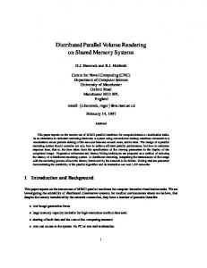
2.1 Auto-Stereoscopic Displays Multi-view auto-stereoscopic displays provide a spatial image, an image that appears to have "real" depth because different views of the displayed 3D data are presented independently to each eye. As illustrated in Figure 1, the infinite number of views an observer perceives in the real world are grouped into different view zones on an auto-stereoscopic display. Each view zone is directionally emitted into the viewing space. The observer perceives a valid spatial image as long as both of his eyes are inside this viewing space. Directional emission is done today by optical filter elements such as lenticular sheets or wavelengthselective filter arrays that are superimposed on standard LCDs. Lenticular sheets consist of long cylindrical lenses that focus on the underlaying image plane so that each vertical pixel stripe corresponds to a view zone. Wavelength-selective filter arrays differ in that the lenses are diagonally arranged and each color channel of an RGB-pixel corresponds to a different view. Multiple views are generated using spatial multiplexing. For N views this reduces the horizontal resolution m by the factor 1/N for lenticular sheets, while using wavelength-selective filters, this reduction is limited to only 3/N • m.
Figure 1. Auto-stereoscopic display principle: Discretization of an infinite view space into finite number of view zones
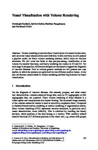
2.2 View Geometry View zones are geometrically represented as off-axis asymmetric sheared view frusta. The intersection of these frusta defines the visible area of a 3D scene. As illustrated in Figure 2, each frustum is placed on the camera plane, at a focal distance fd away from the focal plane. The parallax of a point projected onto a pixel on the screen depends in this multi-view configuration on its distance d from the camera plane and the position of the focal plane. We define the parallax of a view i as the offset offi parallel to the camera plane. From a canonical symmetric center view perspective projection the parallax in a pixel is defined by (1)
where vdi is the camera offset of view i and d is the distance of the visible point from the camera plane. Hence the parallax is zero if a point is on the focal plane and grows with its distance d from the focal plane. A point appears to be further behind the physical display screen for d > fd or in front of the screen for d < fd.
Figure 2. Multi-View parallax geometry
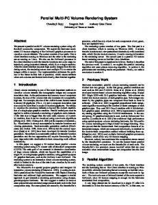
2.3 Image Generation Method The basic approach of a multi-view rendering system, is to render the 3D data in N passes to N intermediate images, that are combined into one spatial image conforming to the auto-stereoscopic display. Using optical filters, this is achieved by masking the (sub-) pixels of each view according to the multi-view mask as shown in Figure 3. For lenticular sheet displays (Figure 3a) the mask function is given by x mod N. For wavelengthselective filter arrays (Figure 3b) the masking function is only slightly more complex as it incorporates masking the individual RGB components per pixel and includes a diagonal shift as illustrated below.
a)
b)
Figure 3. Interleaved Multi-view selection masks for a) lenticular sheets and b) wavelength-selective filter arrays (N=8)
The basic multi-view display algorithm, rendering of N full-resolution images followed by N-fold image masking and compositing, leads to an N times cost increase. To improve performance, intermediate images can be rendered at sub-resolution and restored to full-resolution during compositing by up-sampling at the expense of blurring artifacts. In contrast, our proposed multi-view DVR algorithm will require only a single rendering pass at full resolution, no subsequent image compositing and masking, and exhibits no blurring.
3. SINGLE-PASS MULTI-VIEW VOLUME RENDERING 3.1 Overview Our multi-view DVR algorithm is based on hardware accelerated 3D texture mapping [Cabral et al 1994, Gelder and Kim 1996, Meissner et al 1999]. We make use of pre-calculated voxel gradients which allow the use of high quality gradient estimation filters like the Sobel 3D operator [Jain 1989], and compared to on-thefly gradient estimation in the shader [Engel et al 2006] achieve higher rendering speeds. Pre-calculated gradients come at the expense of increased memory cost. However, at this time we are not focusing on very large data sets, and store the volume data into one 3D RGBα-texture with gradient and scalar values in the RGB and α channels respectively. To improve visual quality, classification of the scalars is done by preintegration as proposed in [Engel et al 2001]. The 2D pre-integration table is calculated and updated from the transfer function and kept in another 2D RGBα-texture. For shading and multi-view rendering our algorithm works significantly different from prior methods. In a single rendering pass we generate and illuminate multiple views directly on the GPU according to the multi-view parallax geometry illustrated in Figure 2 and the per-pixel or sub-pixel view i determined by the view mask in Figure 3. Section 3.3 explains the details of our implementation.
3.2 3D Texture Based DVR Hardware accelerated 3D texture based volume rendering is performed by defining a proxy geometry e.g. a stack of viewport-aligned quadrilaterals (Figure 4a), with each quad having the size of the volume diagonal. Interpolated texture coordinates on the proxy geometry are used to sample the volume, and to extract scalar as well as gradient values. Gradients and scalars from the 3D texture are trilinearly interpolated. The number of proxy quads defines the volume sampling in z-dimension and is usually set to the volume resolution if preintegration is used. While increasing the number of quads improves image quality, fewer quads result in higher frame rates. The stack of quadrilaterals is set parallel to the viewport and camera plane (Figure 2). Rotation of the volume is achieved by reorienting the 3D texture (Figure 4b). To avoid excessive texture lookups and fragment processing, 3D volume aligned clipping planes are specified such that only the clipped quads are processed (Figure 4c).
a)
b)
c)
Figure 4. 3D volume texture mapping. a) Quadrilateral proxy geometry. b) Rotated 3D volume with viewport aligned quads. c) Proxy geometry clipped to rotated 3D volume
The proxy geometry is rasterized as clipped quadrilaterals on screen. The 3D texture volume is sampled for each generated fragment for two scalar values and gradients. The scalar values define a linear segment used to reference into the pre-integration table. Pre-integration reduces artifacts caused by high frequencies in the transfer function which otherwise require higher sampling. Using the volume gradients and lighting parameters, for each fragment (x,y) of every slice k the lighting equation is evaluated yielding a color Ck(x,y). Rendering the slices back-to-front (k=0...K), the direct volume rendering integral is incrementally approximated by , where is the background color. Colors must be pre-multiplied with opacity α, which is the case for pre-integration.
3.3 GPU Based Multi-View DVR Our multi-view volume rendering algorithm makes use of the OpenGL Shading Language [Kessenich 2006]. It is entirely shader based which eases the integration into the vertex and shader programs of existing volume rendering algorithms. A standard vertex shader used for pre-integration [Engel et al 2006], computes the clipped vertex position, transformed texture coordinates and the coordinates of the linear segment used for pre-integration. For multi-view volume rendering we additionally compute the viewport-parallel direction of the parallax offset offi in texture space. We also have to pass the eye-space distance d – from the proxy quad to the camera plane – to the fragment shader, for calculating the multi-view parallax offsets as in Equation 1. In the fragment shader, the 3D RGBα volume texture, the 2D RGBα pre-integration table as well as the multi-view configuration parameters (focal distance, camera offset) are passed as uniform variables from the application. According to the multi-view masks illustrated in Figure 3, there is one or three views to consider for each fragment (x,y). Let us consider the more complex sub-pixel wavelength-selective filter mask here. Hence before calculating a multi-view parallax offsets offi the required views need to be determined. The wavelength-selective filter mask (Figure 3b) has a reoccurring pattern of size 8 × 12. For a fragment (x,y), the xoffset and yoffset of the first sub-pixel component (R) inside this mask are given by the Equations 2 and 3. Fragment coordinates (x,y) in window space are available in the shader through gl_FragCoord. xoffset = (3 • x) % 8 yoffset = (screen_height_in_pixels - y) % 12
(2) (3)
Equation 4 specifies the first view vR of a fragment considering the diagonal filter mask pattern from Figure 3b. The other views are vG = (vR +1) % 8 and vB = (vR +2) % 8. (4)
After knowing the view for each sub-pixel of the fragment, the multi-view offsets offi can be calculated based on Equation 1. The targeted auto-stereoscopic display has N=8 possible views. Hence vdi translates for a given view i at a fixed intraocular distance iocd to vdi = (i - 3.5) • iocd, and the final equation for calculating the offset for a particular view is thereby (5)
with the intraocular distance iocd and focal distance fd given by the application. For each view the texture coordinates of the pre-integrated segments are calculated by an offset along the parallax direction, and the 3D texture lookups provide two gradient and scalar values. The scalar values index into the pre-integration table for the corresponding color and opacity values. Lighting uses the averaged and normalized volume gradients as surface normals in the Blinn-Phong shading model , with the ambient, diffuse and specular light intensity Ia,d,s, reflection coefficients ka,d,s and shininess factor sh. All three sub-pixel views are shaded independently depending on the direction of the surface normal. Note that current GPUs do not support a different α value per color channel for α-blending. Thus at this time we average the fragment's α over the three contributing views. Nevertheless, comparing to a multi-pass multi-view implementation not exhibiting this restriction, no visual artifacts are noticeable (Figure 5).
4. RESULTS In this section we compare our single-pass multi-view volume rendering algorithm (GPU-MV) to a standard N-pass (MV) and a N-pass sub-resolution (MV sub-res) volume rendering method, as well as to a baseline standard single-view (SV) implementation. To analyze the basic behavior, all algorithms use the same code base without specific enhancements as reported in literature (e.g. such as [Kniss et al 2001], [Boada 2001] or [Li et al 2003]), but including the clipping outlined in Section 3.2. Our implementation is based on OpenGL 2.0 and OpenGL Shading Language 1.1, and tested on a 2.66GHz MacPro with a ATI Radeon X1900 graphics card supported by 512MB. For efficiency, the standard
Table 1. Performance comparison at 512 × 512 output window resolution with N=8 views (in fps)
Dataset Buckyball Neghip Hydrogen Engine Skull
Resolution SV 3
32 3 64 3 128 3 256 3 256
463 241 89 15 15
Table 2. Performance comparison at 1900 × 1200 output window resolution with N=8 views. MV sub-res generates the final result from up-scaling an image rendered at 512 × 512 pixels (in fps)
MV
GPU-MV
Dataset
SV
8 MV
8 MV sub-res GPU-MV
51 29 10 1.9 1.8
128 57 26 8.3 7.8
Buckyball Neghip Hydrogen Engine Skull
116 58.8 24.8 6.4 5.9
12.8 6.8 3.3 0.9 0.8
39 25.6 10.5 1.9 1.8
Chart 1. Comparison of multi-view volume rendering in percentage of single-view volume rendering performance 2 for different data sets (N=8 views, 512 window)
26.6 11.9 5.5 2.1 2
Chart 2. Comparison of stereo volume rendering in percentage of single-view volume rendering performance 2 for different data sets (N=2 views, 512 window)
multi-view algorithms (MV) use a render-to-texture approach, and multi-texturing of the N view images for compositing and masking of the final spatial image. The tested multi-view auto-stereoscopic display device uses wavelength-selective filter arrays and has a resolution of 1900 × 1200. Hence it makes use of a sub-pixel resolution view mask as shown in Figure 3b. The GPU-MV volume rendering algorithm, therefore, has to compute three different views – one for each RGB component – per processed fragment. Consequently, the performance of GPU-MV can be expected to be significantly better for lenticular sheet displays with only a single view per pixel. In Table 1 we report frame rates for generating (N=8)-view spatial images at 512 × 512 resolution for different standard volume data sets. As expected, we can observe that the standard MV algorithm suffers significantly from the 8 rendering passes it has to perform. The expected performance ratio of 8:1 between SV and MV roughly holds, and GPU-MV improves over MV by a factor of ≈ 2-4. Moreover, we can see that the theoretical ratio of 3:1 between SV and GPU-MV holds for medium datasets and, moreover, that our algorithm performs increasingly better for larger data (Chart 1). Table 2 shows that the sub-resolution approximation (MV sub-res) can improve performance over 3 standard MV for large 1900 × 1200 output resolution. For small data sets ≤ 128 MV sub-res can even perform better than our GPU-MV, but at the expense of significant blurring artifacts due to the up-sampling of the final image from a low-resolution rendering (see also Figure 6c). At the same image quality, the N-pass volume rendering algorithm MV achieves dramatically lower frame rates compared to GPU-MV (Figures 6a, b). In Figure 5 we can see that our novel multi-view volume rendering algorithm generates an image quality indistinguishable from a standard full-resolution 3D texture based volume rendering approach, but at significantly higher performance. For comparison, we also implemented a multi-pass GPU approach that only calculates fragments corresponding to views which will survive the subsequent image compositing and masking stage. Thus we exactly perform the texture lookups for the minimally necessary fragments. While novel auto-stereoscopic displays with wavelength-selective filter arrays may only marginally benefit from this approach because of
the sub-pixel view resolution, lenticular sheet displays seem to be an optimal target as only N • 5122/N fragments must be generated instead of N • 5122. However, the lack of real branching and fragment discarding in current GPUs make it necessary to perform a pre-pass for each view. This pass initializes the depth buffer such that only fragments of the corresponding view will pass the z-visibility test. Early z-culling should prevent processing unnecessary fragments in the following standard multi-pass volume rendering. Results in Chart 2 show that the simple multi-pass GPU approach (z=1) has no performance advantage compared to standard two-pass rendering (2 MV). The reason for this is the granularity of early z-culling used by the GPU which is typically coarser than a single-fragment [Lefebvre 2005]. Hence only if the size of a view spans more than one pixel we can achieve some performance gains from early z-culling, as supported by our experiments with two and four pixels per view (z=2, z=4 in Chart 2). This renders this idea not practicable for per-pixel or even sub-pixel based multi-view rendering.
b)
a)
c)
d)
Figure 5. Two views rendered using our single-pass multi-view volume rendering at 59 fps (a) and at 57 fps (b), and using a standard multi-pass volume rendering at 31 fps (c) and at 29 fps (d). (512 × 512 window resolution, N=8 views)
a)
b)
c)
Figure 6. a) Single-pass multi-view volume rendering at 8.3 fps. b) Multi-pass volume rendering at 1.9 fps. c) Subresolution (256 × 256 up-scaled) multi-pass volume rendering at 3 fps. (512 × 512 window resolution, N=8 views)
5. CONCLUSION In this paper we have presented a new multi-view 3D texture based volume rendering algorithm that can generate a spatial N-view image in one single rendering pass. The targeted spatial images include formats for lenticular sheet or wavelength-selective filter array based auto-stereoscopic display devices. The presented solution is significantly faster than a standard multi-pass multi-view rendering approach while obtaining the same image quality. We formulate the parallax as an offset as introduced in Section 2 depending on the camera offset from a canonical center-view and the distance of a fragment to the camera plane. This allows us to determine arbitrary views and their parallax offsets during fragment processing as shown in Section 3. Also the multiview masking can efficiently be performed on a per-pixel basis directly in the fragment shader. Consequently
a single-pass algorithm can be achieved which implements a basic 3D texture based volume renderer with a modified fragment shader. The basic observations and implementation made in this paper have great potential to extend to other areas of multi-view rendering. We believe that the parallax view offset definition cannot just be applied to 3D texture volume rendering but with some modifications and extensions also to polygonal rendering. An example approach has been shown for point-based rendering in [Huebner et al 2006]. A generic extension will be studied in future work as well as the better understanding of geometric properties and distortions of multi-view auto-stereoscopic displays.
REFERENCES Adelson, S. J. and Hansen, C. D., 1994. Fast stereoscopic images with ray-traced volume rendering. Proceedings ACM/IEEE Symposium on Volume Visualization. Tysons Corner, USA, pp. 3-9. Boada, I. et al, 2001. Multiresolution volume visualization with a texture-based octree. The Visual Computer. Vol. 17, No. 3, pp. 185-197. Brodlie, K. and Wood, J., 2001. Recent Advances in Volume Visualization. Computer Graphics Forum, Vol. 20, No. 2, pp. 125-148. Cabral, B. et al, 1994. Accelerated volume rendering and tomographic reconstruction using texture mapping hardware. Proceedings ACM/IEEE Symposium on Volume Visualization.Tysons Corner, USA, pp. 91-98. Dodgson, N. A., 2002. Analysis of viewing zone of multi-view autostereoscopic displays. Proceedings of SPIE, Vol. 4660, The International Society for Optical Engineering, pp. 254-265. Dodgson, N. A., 2005. Autostereoscopic 3D displays. IEEE Computer, Vol. 38, No. 8, pp. 31-36. Ebert, D. et al, 1996. Two-handed interactive stereoscopic visualization. Proceedings IEEE Visualization 96. San Francisco, USA, pp. 205-210. Engel, K. et al, 2001. High-quality pre-integrated volume rendering using hardware-accelerated pixel shading. Proceedings of the ACM SIGGRAPH/EUROGRAPHICS workshop on Graphics hardware. Los Angeles, USA, pp. 916. Engel, K. et al, 2006. Real-time volume graphics. A K Peters, Wellesley, USA. Gelder, A. V. and Kim, K., 1996. Direct volume rendering with shading via three-dimensional textures. Proceedings ACM/IEEE Symposium on Volume Visualization, San Francisco, USA, pp. 23-30. He, T. and Kaufman, A., 1996. Fast stereo volume rendering. Proceedings IEEE Visualization 96, San Francisco, USA, pp. 49-56. Huebner, T. et al, 2006. Multi-View Point Splatting. Proceedings Conference on Computer Graphics and Interactive Techniques in Australasia and South-East Asia (GRAPHITE), Kuala Lumpur, Malaysia, pp. 285-294, 499. Jain, A. K., 1989. Fundamentals of Digital Image Processing. Prentice Hall, New Jersey, USA. Kakimoto, M., 2005, Interactive Stereo Library (ISL). Joint Meeting on 3D Technology. London, England, http://www.sgi.co.jp/solutions/visualization/isl. Kessenich, J. et al, 2006. OpenGL Shading Language. OpenGL.org. http://www.opengl.org/documentation/glsl. Kniss, J. et al, 2001, Interactive texture-based volume rendering for large data sets. IEEE Computer Graphics and Applications, Vol. 21, No. 4, pp. 52-61. Koo, Y. M. et al, 1999, Object-order template-based approach for stereoscopic volume rendering. Journal of Visualization and Computer Animation, Vol. 10, No. 3, pp. 133-142. Lee, Y. G. and Ra, J. B., 2005, Reduction of the distortion due to non-ideal lens alignment. Proceedings of SPIE, Vol.5664, pp. 506-516. Lefebvre, S. et al, 2005, GPU Gems 2 - Programming Techniques for High-Performance Graphics and General-Purpose Computation. Addison Wesley, Boston, USA. Li, W. et al, 2003, Empty space skipping and occlusion clipping for texture-based volume rendering. Proceedings IEEE Visualization 2003. Washington, USA, pp. 317-324. Lum, E. B. et al, 2004, High-Quality Lighting and Efficient Pre-Integration for Volume Rendering. Proceedings of the Joint Eurographics-IEEE TVCG Symposium on Visualization 2004. Konstanz, Germany. McAllister, D. et al, 1993, Stereo Computer Graphics and other True 3D Technologies. Princeton University Press, Princeton, USA. Meissner, M. et al, 1999, Enabling classification and shading for 3D texture mapping based volume rendering using OpenGL and extensions. Proceedings IEEE Visualization 99. San Francisco, USA, pp. 207-214.
Miniel, S. et al, 2004, 3D functional and anatomical data visualization on auto-stereoscopic display. Proceedings EuroPACS-MIR, Trieste, Italy, pp. 375-378. Portoni, L. et al, 2000, Real-time auto-stereoscopic visualization of 3D medical images. Proceedings of SPIE, Vol. 3976, Medical Imaging 2000: Image Display and Visualization, pp. 37-44. Rezk-Salama, C. et al, 2000, Interactive volume rendering on standard PC graphics hardware using multi-textures and multi-stage rasterization. Proceedings of the ACM SIGGRAPH/EUROGRAPHICS workshop on Graphics hardware. Interlaken, Switzerland, pp. 109-118. Schmidt, A. and Grasnick, A., 2002, Multiviewpoint autostereoscopic dispays from 4D-Vision GmbH. Proceedings of SPIE, Vol. 4660, The International Society for Optical Engineering, pp. 212-221. Schneider, J. and Westermann, R., 2003, Compression domain volume rendering. Proceedings IEEE Visualization 2003. Washington, USA, pp. 39-48. Wan, M. et al, 2004, Interactive stereoscopic rendering of volumetric environments. IEEE Transactions on Visualization and Computer Graphics, Vol. 10, No. 1, pp. 15-28.