Sizing algorithm with continuous customizable clipping. Domingo Morales, Felipe Baytelman, Hugo Araya. Synopsys Chile R&D Centerâ Vitacura 5250 suite ...
Sizing algorithm with continuous customizable clipping Domingo Morales, Felipe Baytelman, Hugo Araya Synopsys Chile R&D Center– Vitacura 5250 suite 708, Vitacura, Santiago (CHILE) ABSTRACT
Polygon sizing is required during Mask Data Preparation in order to generate derived layers and as process bias to account for edge effects of etching. Two main features are required for polygon sizing algorithms to be useful in Mask Data Preparation software: correctness to avoid data corruption and clipping of the projection of acute angle vertices to limit connectivity modifications. However, current available solutions are either based on heuristics, producing corrupted results for certain input, or based on algorithms which may fail to maintain original design’s connectivity for certain input. A novel algorithm including customizable clipping is presented. Keywords: Sizing, Mitered Offsetting, Fracture, Mask Data Preparation (MDP) 1. INTRODUCTION
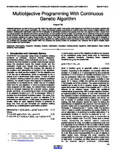
Polygon Sizing, also known as Sizing, Mitered Offsetting or just Offsetting, is a procedure applied to oriented polygons producing zero or more polygons. Sizing expands or shrinks the polygon in such a way that every edge in the resulting polygon is parallel to an edge in the original polygon and located at a constant distance in the interior or exterior of the region defined by the original polygon. The constant distance between original edges and corresponding edges in the resulting polygon is referenced as the sizing distance or sizing amount. See Figure 1 for sizing examples. We refer to sizing results as the sized polygons. SWOflUJ2 O OAGL
2!G
JJJ!2 2fl boi1ou q!229bG9L2 c p!Lq 9WOfl UI O
3 SWOOUI2 01 flUGL 2!G
boIäou OA I2!6
p bolAäou nuqei 2!6
Figure 1. A simple polygon with both over-size (left) and under-size (right) for three sizing amounts.
Photomask Technology 2008, edited by Hiroichi Kawahira, Larry S. Zurbrick, Proc. of SPIE Vol. 7122, 71224A · © 2008 SPIE · CCC code: 0277-786X/08/$18 · doi: 10.1117/12.805595
Proc. of SPIE Vol. 7122 71224A-1 2008 SPIE Digital Library -- Subscriber Archive Copy
Positive sizing, also known as over-size, expands the polygon, projecting original edges toward the exterior region defined by the original polygon, increasing its area. On the other hand, negative sizing, also known as under-size, projects original edges towards the interior region defined by the original polygon, reducing its area. Negative sizing may generate results with zero polygons (Figure 1.b). Sizing is a technique used in several fields, from collision detection to urban architecture. Some of these examples are: -
Rapid prototyping requires robotic laser path planning to consider the laser width in order to create the desired output, therefore original design must be over-sized to plan the laser path avoiding final creation to be smaller than designed [1].
-
Robotic path planning uses polygon over-size to prevent robots collisions against obstacles and terrain irregularities [2] [3].
-
Based on architecture blueprints representing walls, roof structure can be calculated using both over and under-size [3].
-
2D and 3D mesh construction application use polygon positive-sizing to fill gaps in order to simplify mesh triangulation [4].
-
Graphic design problems [8][9][10].
-
EDA industry uses sizing process as part of verification and MDP tools [11][12].
1.1 Sizing implementations Existing algorithms allow correct sizing results. However, they are complex to implement and they do not provide all features required in every field. In order to obtain simpler implementations and obtain additional features, several heuristics have been implemented. Regarding MDP software, implementations are based either on heuristics or algorithms, but they cannot provide a complete solution that addresses all requirements for this field. Sections 2.1.1 to 2.1.3 describe current alternatives limitations. 1.2 Sizing as a tool in MDP Sizing serves for several purposes during mask data preparation [5], including: -
De-sliver operations in layer derivation steps in order to remove small gaps and spikes [5].
-
Generation of derived layers, such as P-well and N-well, large over-size is applied to P and N layers’ data.
Proc. of SPIE Vol. 7122 71224A-2
-
Sizing is used during MDP as process bias to account for edge effects of etching. During wafer processing, distortions may occur during the etching stage (overetching). Over-sizing or under-sizing the mask data compensates this [6] [7].
As described in section 2, current available solutions cannot address the two main features required for correct sizing in MDP tools: These solutions fail either generating corrupt results because of heuristics restrictions, or cannot limit the projection of acute angles when sizing process creates connectivity changes because of post-processing clipping restrictions. Section 3 describes the requirement for solving the presented problems, and proposes a new sizing algorithm for oriented non self-intersecting polygons, which produces correct output and allows customized clipping to be applied to acute angles, limiting connectivity changes. In section 4, practical results of this algorithm’s implementation are presented. Finally, section 5 summarizes our conclusions. 2. THE PROBLEM
This section describes why sized polygon clipping is relevant in MDP, because it limits the projection of acute angle vertices. Available solutions are described, including heuristics which provide incorrect results, as well as algorithms which cannot provide continuous output. 2.1 Clipping the projection of acute angle vertices In the sizing processing, vertices from the original polygon move along their bisectors. Each vertex must move a distance depending on its bisector angle, ensuring that edges remain parallel to the original one. The more acute an angle is, the further such vertex is projected. Therefore, if a polygon contains very acute angles, over-size results will be disproportionally big as some vertices will project too far. See Figure 2 for an example of the sizing result of two similar polygons.
a.
b.
Figure 2. Two similar original polygons produce very different results for an over-size operation due to an acute angle. Note how even when the polygon on the left has an original area very similar to the polygon on the right. However, as sizing amount grows, the acute vertex projection generates much wider results, covering much more area.
Proc. of SPIE Vol. 7122 71224A-3
Although this might be a correct result from a mathematical perspective, resulting vertices projected far from their original position may jeopardize electronic designs by altering its original connectivity. Figure 3 shows an example of a design affected by different sizing amounts. Note how the acute angle vertex projects faster than other vertices, reaching the opposite part of the design.
Figure 3. Acute angles vertices project too far, jeopardizing the original polygon’s connectivity.
Clipping of acute angles allows limiting the projection of sized vertices, resembling the original design more effectively and preventing connectivity changes. Sized polygons with clipped acute angles are more similar to the original polygon when compared with non-clipped results, both in surface area and overall vertex-vertex distance. Moreover, the relation between original and clipped sized polygons seems more intuitive and natural for the human observer than the relation between original and non-clipped sized polygons. Figure 4 represents the clipped version of previous example from Figure 3. Note how the clipped result resembles the original polygon more effectively.
Figure 4. Clipping acute angles avoids acute angles to project too far, preventing connectivity changes.
2.1.1. Current available solutions Today, there are tools which allow applying sizing to polygons. These tools are available for several fields and applications from 2D graphical editors [8][9][10] to EDA tools, including physical verification [11] and MDP software [12].
Proc. of SPIE Vol. 7122 71224A-4
However, most of these tools provide a limited solution regarding sizing, which does not fulfill MDP software requirements: correctness and retaining connectivity through corner clipping (see section 3.1 for additional details on required features). The reason why these solutions’ sizing operations cannot fulfill the MDP software requirements is because their sizing procedures are based either on heuristics or algorithms with discontinuous clipping. 2.1.2. Heuristics and non-local data corruption Heuristics are problem-solving techniques in which the most appropriate solution is selected using a limited set of rules. Instead of applying complex formulas and/or algorithms, heuristics quickly produce a solution. However, heuristics’ solutions may not obtain the correct answer in certain cases. Heuristics-based sizing procedures are based on a limited set of rules. Therefore, only limited families of problems can be solved correctly with these procedures. Following examples (Figure 5) show a simple case where heuristics cannot produce the correct solution for sizing, producing corrupted data. In this case the heuristic performs local sizing. The polygon is fractured into trapezoids and each trapezoid is sized considering only their immediate neighbors. The partial sized results are clipped and combined removing overlaps. This heuristic introduces an incorrect result in this case. Compare it against the correct result (Figure 5.c).
a. Original polygon
b. Result of local sizing heuristic c. Correct sizing results
Figure 5. Heuristics could fail even with simple cases.
2.1.3. Post-Clipping of acute angles causes connectivity changes Several algorithms have been proposed to solve the sizing problem. These algorithms, however, do not include any method to avoid acute corners to project far from the original polygon during sizing. Figure 2.b and Figure 3 show results for different polygons, which, after sizing, become very different from the original or did not retain their original connectivity. In order to mitigate this problem, some algorithms analyze the produced polygon after sizing has finished (post-processing clipping), comparing how vertices projected away from their origin.
Proc. of SPIE Vol. 7122 71224A-5
When an angle is acute and the sized vertex has been projected further than certain distance, then that corner is clipped. Figure 6 shows examples of acute angle clipping for different cases.
2!Gq bOIaou
qeuA scne su Iiee
VIGL CI!b1
p
iebnU
Figure 6. Post-clipping generates correct output when sizing prior clipping does not affect acute corners.
iebnU
c-I C) I.1 Cl)
CA)
2WOOTP
S vcne COLLJ6L 2691cp
3 VCfl6 COLLJGL C I!bb!Uä
bO2 2!!uä cI!bb!LJä GAC)IflPOU
C)
ki Cl)
pinb
. a,
Cp9Uäe
Figure 7. Three steps post-sizing clipping: Same polygon is processed using three different sizing distances. First two cases (under-size x1 and x2 rows) generate desirable results. For third case (undersize x3), sizing distance makes the acute angle to reach the opposite edge, splitting the polygon. Then, during stage 2, no acute corner is found; therefore no clipping is applied on stage 3. Last column shows how all three cases compare. Notice how the lack of clipping produces abrupt or discontinuous changes in the results evolution.
Although this technique mitigates the issues produced by the projection of acute angles in some cases, it fails when the projection produces connectivity changes. Once the projection becomes in touch with an opposite edge, then the whole polygon is modified. Thus, when the post-clipping
Proc. of SPIE Vol. 7122 71224A-6
reviews the generated polygon, merged acute angles would no longer be selected for clipping, because such angles are not longer acute, and do not correspond 1:1 to original vertices. A simple example is based on applying under-sizing to a rectangle with a small V-shape cut as shown in Figure 7. While sizing distance is small enough to avoid the acute angle to reach the opposite vertex, result still has the same acute angle. Then, partial result is reviewed in search of acute corners. When found, these corners are clipped. However, when the sizing distance is big enough to allow the acute angle to reach the opposite edge, the sized vertex splits the polygon in two. Once the polygon has been split in two, the splitting vertex cannot be clipped. Although sizing distance is very similar, results right before the acute vertex reaches the opposite edge and right after the vertex has reached such edge are very different. Figure 7 shows how this problem may lead to abrupt changes, producing discontinuity in the results for continuous increments of the sizing distance. 3. SIZING ALGORITHM WITH CONTINUOUS CUSTOMIZABLE CLIPPING
As mentioned in previous section, required features for sizing to be a useful tool in MDP software include results correctness and clipping of the projection of acute angles. This section emphasizes on how both of these requirements lead to a new solution. Then, a solution is built in order to address such needs. 3.1 Solution requirements 3.1.1. Correct algorithm Heuristics do not provide a mathematical guarantee that results will be correct for any input. This combined with the increasing complexity of the mask designs defines the first requirement: A new solution must be based on a mathematically proven algorithm, which can provide a correct solution for all valid input. In this case, we need a well defined algorithm which handles all non self-intersecting polygons correctly. 3.1.2. Clipping of acute angles Although some solutions offer corner clipping of acute angles, they cannot ensure continuous evolution of the clipped result as the sizing amount is incremented. In fact, as described previously, post-processing clipping is not able to clip corners after they have merged against an opposite edge. However, if the resulting polygon would evolve continuously, we would expect such merging to occur at a much bigger sizing distance. Figure 8 shows an example of the expected evolution of the sizing procedure for the same case previously seen in Figure 7. Note how the sizing distance required for the definitive split (and therefore a connectivity change) is much bigger than the one required with post-clipping algorithms.
Proc. of SPIE Vol. 7122 71224A-7
Also note how the resulting shapes have a continuous evolution: For small sizing distance differences, result should not vary abruptly (Figure 8’s comparative evolution is smooth). On the other hand, post-processing clipping algorithms introduce abrupt changes for small sizing distance differences (Figure 7’s abrupt change is marked on red). 'I
5
3
flUGL
flUGL 2!G X2
C0WIL4!Ab !!UU bIUII1J.!UU
Figure 8. Expected evolution of sizing with clipping for different sizing distances.
Therefore, a complete solution cannot be based on post-sizing corner clipping, because they cannot handle past corner merging into opposite edges, restricting the solution scope. A new solution must be based on a clipping mechanism that provides continuous results for continuous incremental sizing amounts, avoiding abrupt changes in the resulting polygon for similar sizing distances. 3.2 Solution construction 3.2.1. Original sizing algorithm As described in section 3.1.1, a complete solution requires to be based on an algorithm that handles any kind of evolution during the sizing calculation. In sizing algorithms, vertices are projected through their angle’s bisectors. All vertices are projected at certain speed which ensures that resulting edges remain parallel to the original ones, while being shifted all together at the same rate. Figure 9 shows an example of a polygon’s sizing evolution during a sizing algorithm. 3.2.2. Clipping-aware continuous sizing Sizing algorithms must be modified to provide continuous results with clipping. Applying clipping once sizing has finished is proven not to provide continuous results (Figure 7). In order to generate adequate results with no abrupt changes, clipping-awareness must be incorporated during the entire process. In Figure 9, the evolution of the sizing for certain polygon shows how clipped corner’s vertices interact.
Proc. of SPIE Vol. 7122 71224A-8
Figure 9. Modified sizing algorithm: Clipped corners evolve smoothly during sizing.
Detection and processing of clipped corners is also included in the modified algorithm, obtaining continuous results for all cases. Figure 10 compares two examples of complex setups: with original post-processing algorithm, results are discontinuous, while the new algorithm provides smooth evolution of clipped corners, ensuring continuity.
CI!bbluä VEIEI
!uä
CI!bbluä DflIII'lG
Figure 10. Two examples where clipping after sizing cannot prevent acute angles from modifying the resulting topology. Lines in red shows the comparison when clipping after sizing looses continuity. For the same sizing distance, clipping during sizing provides continuous result.
3.3 Customizable clipping Different applications may require different types of clipping. This feature is not a mathematical requirement: Indeed, clipping of acute angles has been conceived as an on-demand feature. In fact, there are multiple alternatives on how clipping could be applied. In the electronic design industry, corner clipping is meant to retain original design connectivity as much as possible, while in other fields clipping may be required for different goals. Basic clipping is often defined by two concepts: Clipping nature and clipping distance.
Proc. of SPIE Vol. 7122 71224A-9
The most intuitive clipping nature would be making an orthogonal cut to the corner’s bisector. Such direction is determined by the vertex’s bisector, as seen in Figure 11.c. For some applications in EDA, this type of clipping is useful, like physical verification [11]. However, in MDP, introducing additional diagonal edges to the mask design data may be undesirable: In this case, horizontal and vertical cuts (straight cuts) are preferred (Figure 11.d).
OL!ä!u9I pgbG
Figure 11.
p 2!!uä M!f4JOfl CI!k)bIuä
OLflJoäousI CI! )b!Uä
q 2L9iäp cI!bbiuä
Different custom clipping could be applied to sized polygons.
4. RESULTS
The proposed algorithm has been implemented based on one mathematical proven sizing algorithm. This has been modified in order to handle corner clipping. As a result, this sizing algorithm generates correct output, providing customizable clipping with desirable continuity of results. The solution is part of Synopsys’ CATS. The correctness of the results has been confirmed by quality assurance procedures. Extensive validation going from unit to stress testing confirms that this algorithm fulfills the requirements posed in Section 3.1. 5. CONCLUSIONS
The requirements for a practical sizing algorithm in the context of MDP have been presented. A review of the state of the art solutions shows that they cannot fulfill those requirements, because either they produce corrupt results or because connectivity changes does not allow all acute angles to be clipped. A novel algorithm has been proposed in order to provide mathematical correctness for polygon sizing problem including customizable continuous clipping. Results obtained with this algorithm have been proven to address required features of the MDP tools, including correctness, acute angles clipping and continuity.
Proc. of SPIE Vol. 7122 71224A-10
REFERENCES
[1]
Z Jibin, L Weijun, W Yuechao – “Study on Algorithm of Contours Path Generation for Robotic Prototyping”, IEEE International Conference on Robotics and Biomimetics 2004.
[2]
SW Cheng, A Vigneron – “Motorcycle Graphs and Straight Skeletons”, Algorithmica, 2007 – Springer
[3]
D Eppstein - “Raising Roofs, Crashing Cycles, and Playing Pool: Applications of a Data Structure for Finding Pairwise Interactions”, Discrete and Computational Geometry, 1999 – Springer
[4]
SC Park, YC Chung – “Mitered offset for profile machining”, Computer-Aided Design, 2003 Elsevier
[5]
S. Rizvi – “Handbook of Photomask Manufacturing Technology”, 2005, pp. 25 - Taylor & Francis
[6]
F Amoroso, M Cote, T Do, R Lugg, J Nogatch – “Fracture friendly optical proximity”, Proceedings of SPIE, 2005
[7]
SM Rubin – “Computer aids for VLSI design”, Addison-Wesley, 1987
[8]
Microsoft Visio 2003, Microsoft Corp. - http://office.microsoft.com/en-us/visio/
[9]
Adobe Illustrator CS3, Adobe Systems Inc. - http://www.adobe.com/products/illustrator/
[10] Inkscape, The Inkscape Team - http://www.inkscape.org/ [11] Hercules , Synopsys Inc. - http://www.synopsys.com/products/hercules/ [12] CATS, Synopsys Inc. - http://www.synopsys.com/products/ntimrg/cats_main_ds.html
Proc. of SPIE Vol. 7122 71224A-11