Wenyong Gong1,5. Qi Su1,6. Baoquan Chen1,7,8â . 1Shenzhen Institutes of Advanced Technology, Chinese Academy of Sciences 2National University of ...
DOI: 10.1111/cgf.12200
COMPUTER GRAPHICS
forum
Volume 32 (2013), number 8 pp. 233–245
Sketch-to-Design: Context-Based Part Assembly Xiaohua Xie1,2 , Kai Xu1,3 , Niloy J. Mitra4 , Daniel Cohen-Or5 , Wenyong Gong1,6 , Qi Su1,7 and Baoquan Chen1,2,8
1 Shenzhen
Institutes of Advanced Technology, Chinese Academy of Sciences 2 Shenzhen VisuCA Key Lab, China 3 National University of Defense Technology, China 4 University College London, UK 5 Tel Aviv University, Israel 6 Jilin University, China 7 South China University of Technology, China 8 Shandong University, China {sysuxiexh, kevin.kai.xu, niloym, cohenor, gongwenyong, suqi87, baoquan.chen}@gmail.com
Abstract Designing 3D objects from scratch is difficult, especially when the user intent is fuzzy and lacks a clear target form. We facilitate design by providing reference and inspiration from existing model contexts. We rethink model design as navigating through different possible combinations of part assemblies based on a large collection of pre-segmented 3D models. We propose an interactive sketch-to-design system, where the user sketches prominent features of parts to combine. The sketched strokes are analysed individually, and more importantly, in context with the other parts to generate relevant shape suggestions via adesign galleryinterface. As a modelling session progresses and more parts get selected, contextual cues become increasingly dominant, and the model quickly converges to a final form. As a key enabler, we use pre-learned part-based contextual information to allow the user to quickly explore different combinations of parts. Our experiments demonstrate the effectiveness of our approach for efficiently designing new variations from existing shape collections. Keywords: sketch-based modelling, assembly-based modelling, context, interface design ACM CCS: 1.3.5 [Computer Graphics]: Computational Geometry and Object Modelling—Constructive solid geometry
1. Introduction
A successful 3D modelling system should be simple, interactive, intuitive to use and facilitate design exploration. To this end, in our sketch-driven part-based modelling system the user roughly sketches parts, while the system retrieves and ‘assembles’ parts from a model database to create a complete shape. Such a compositional system requires solving the three key challenges: (i) using rough user-strokes to query and recover potential matching parts; (ii) positioning and orienting the retrieved part(s) and (iii) connecting the parts to the current models to form a coherent whole. The input strokes, however, only provide rough and incomplete 2D information. Hence, as a key enabler, we use interpart context information along with the 2D sketches to remove the suggestion ambiguities. By context, we refer to relative arrangement of parts. Thus, in our system, modelling amounts to navigating a space of mix-andmatch models with the user sketches driving the navigation, while
Conceiving shapes from scratch is difficult since early concepts are often fuzzy, ambiguous and not fully formed (cf. [PKM*11]). In the early design stages, artists typically explore multiple conceptual options without finalizing geometric details. For example, artists prefer to start with rough sketches, which they progressively oversketch to eventually converge to a conceptual shape. With a similar motivation, the recent ShadowDraw system [LZC11] uses a datadriven approach to help artists create better and well-proportioned 2D sketches. The approach, however, does not immediately support viewing or editing the evolving conceptual shape in 3D. In this paper, we introduce a sketch-to-design interactive system that directly converts rough user sketches to part-based 3D geometry, thus retaining the fluidity of the sketching process, while facilitating easy 3D model creation.
� C 2013 The Authors C 2013 The Eurographics Association and John Computer Graphics Forum � Wiley & Sons Ltd. Published by John Wiley & Sons Ltd.
233
234
X. Xie et al. / Sketch-to-Design
Figure 1: Starting from an arbitrary 3D chair model (left), the user sketches (in red) over a light ‘shadow’ of the chair. As the session progresses, the user can rotate the current model and sketch over more convenient viewing directions. The user strokes along with symmetry and context information from pre-analysed database models are used to retrieve, deform and snap parts to provide modelling suggestions to the user. Effectively, the strokes guide a part-based design space exploration. part-level relations and contextual information provide computational guidance. In our interactive system, the user roughly sketches parts over a canvas that displays the evolving 3D model in the background. We continuously analyse the drawing strokes and their context to suggest relevant part combinations to the user via a dynamic design gallery. Essentially, for each retrieved part, a corresponding suggestion is generated by appropriately positioning and linking the part to the current design. As the user progressively explores and selects model parts, fewer model parts with compatible context clues are retrieved, thus narrowing down subsequent selection possibilities (see Figure 1). As an analogy, think of an autocomplete option for text search—as the design session progresses, modelling speed increases with fewer part options to select from and hence fewer ambiguities for the user to resolve. Note that parts once selected and positioned are not changed during subsequent modelling steps. Our work is motivated by recent advances in consistent decomposition of models into parts (e.g. [KHS10, HKG11, SvKK*11]) that simplifies subsequent model creation. We make use of relative placement and context information across parts in large collections of semantically segmented parts to allow the user to intuitively select, position and connect parts to produce novel models. Specifically, we pre-analyse a large set of segmented models to learn their contextual relations (e.g. part pairs in contacts, being symmetric counterparts or sharing similar geometric properties) and use the relations for smart design exploration. Since parts are typically small and simple relative to the whole shape, they display less characteristic variations compared to whole shapes. In other words, the visual cues between different parts are less discriminative than those for whole shapes. Hence, purely silhouette-based part retrieval is often too ambiguous making partbased modelling from 2D sketches inherently challenging [LF08]. Instead, as a key contribution, we demonstrate that interpart contextual information is useful, alleviates ambiguities, and significantly boosts part-based compositional modelling. For example, while designing a chair, a rounded chair seat may suggest, with higher confidence, a rounded chair back rather than a squarish one. The correlated features also include geometrical properties internal to the parts (e.g. parallel banisters of a chair back), in addition to simply their outlines. As the modelling session progresses, we make use of such contextual relations to significantly reduce the search space of part assemblies commensurate
with the user sketches, thereby better assisting the user to quickly converge to an appropriate design. We evaluate the effectiveness of our modelling system using a user study and present various models generated using our system (see also Supporting Information Video S1 and demo).
2. Related Work Modelling remains a popular research topic with a host of relevant efforts in recent years. In this section, we focus on a few representative papers relevant to our work. Sketch-based retrieval. Inspired by Funkhouser et al. [FMK*03], many image-based approaches have been proposed towards sketchbased shape retrieval (see [SXY*11] and references therein). Earlier, Chen et al. [CTSO03] propose Light Field Descriptor to encode 2D projections of a 3D shape using a combination of contour- and region-based shape descriptors. This method, however, does not consider the interior feature lines. Eitz et al. [ERB*12] propose a bag-of-words (BOW) based method to encode view-dependent line drawings of the 3D shapes using both silhouette and interior lines. Subsequently, they learn a classifier based on a large set of human-created classified sketches. However, for sketch-based part retrieval, we have to deal with imprecise and less discriminative drawings of shape parts. In a parallel effort, Xu et al. [XCF*13] present Sketch2Scene to construct 3D scenes from 2D sketches based on sketch-based co-retrieval and co-placement of 3D models. We adapt sketch-based retrieval proposed by Lee and Funkhouser [LF08] and additionally achieve robustness using contextual information among pre-analysed parts. Assembly-based modelling. As model collections grow, modelling by part assembly provides a quick way to synthesize new models from the existing ones. In a seminal effort, the modelling-byexample system [FKS*04] rely on shape-based search to find desired parts to assemble. The user provides a rough 3D proxy of the required part, which is then used to query the database of shape parts. While the concept is powerful, the interface is cumbersome requiring users to manually model, position and manipulate proxies in 3D. Although subsequently various improvements have been proposed [SI07, LF08, CK10, FSH11], the methods either require sketching proxy geometry in 3D or restrict view manipulations during any session.
� C 2013 The Authors C 2013 The Eurographics Association and John Wiley & Sons Ltd. Computer Graphics Forum �
X. Xie et al. / Sketch-to-Design
235
Figure 2: System pipeline. Kreavoy et al. [KJS07] propose the Shuffler system to create new models by shuffling interchangeable components between existing models. More recently, Kalogerakis et al. [KCKK12] propose a probabilistic model for automatically synthesizing 3D shapes through automatic model synthesis using training data. Xu et al. [XZCOC12] design part crossover for 3D model set evolution based on part assembly with structural information; while Jain et al. [JTRS12] study interpolation of man-made objects through part recombination. Although such methods produce volumes of shape variations, the methods do not provide the user with finegrained control necessary to facilitate interactive design. Shen et al. [SFCH12] exploit the use of part assembly in recovering high-level structures from single-view scans of man-made objects acquired by the Kinect system. Data-driven suggestions. We draw inspiration from data-driven suggestions for modelling [KHS10, OFCD02] and shadow-guided sketching [LZC11], while sharing motivation from context-based search for models in 3D scenes [FH10, FSH11]. Our focus, however, is to enable an interactive sketch-to-design system to support conceptual design. Thus we continuously present the user with a variety of suggestions, with the user actively guiding the part-based shape space exploration. The context information, updated on the fly, allows robust retrieval of relevant parts thus allowing the user to sketch imprecisely. Zheng et al. [ZCOM13] look at structure of part connectivity and their interrelations to propose non-trivial yet plausible model variations by combining parts from models in and across different model collections.
3. Overview Our system comprise of an offline phase (Section 4) to pre-analyse a 3D candidate part database and an online interactive modelling system (Section 5) driven by sketch-driven context-based part retrieval and assembly (see Figure 2). Offline pre-processing. We assume the availability of 3D model collections (e.g. [OLGM11]). We consider six classes of models in our setup: aeroplanes, chairs, lamps, pavilions, robots and vases and allow users to explore part-based assemblies for creating model variations inside these classes. The input data set is pre-segmented and the parts are grouped by their semantic labels (e.g. legs, slats, seat, wings, handle, etc.) and aligned using upright orientation of the original models. We then extract contextual information among the parts, which we subsequently use during the modelling session to retrieve, place and connect the parts.
Figure 3: A snapshot of our context-based sketch-driven 3D modelling interface. The canvas for sketching is on the bottom right panel; the suggestion panel displaying a gallery of relevant parts is at the top; and the panel showing the evolving model is at the bottom left. User interface. The modelling interface consists of three parts (see Figure 3): (i) a canvas for sketching the model, (ii) a suggestion panel displaying a gallery of relevant parts retrieved from the candidate part database using the user sketch and extracted context information and (iii) a panel showing the current model. For each category of models, we assign a representative model and display it in the suggestion panel in the initial of the system. To start modelling, the user selects a reference model, and hence one category, among these representative models. The reference model is rendered in a Non-Photorealistic Rendering (line drawing) fashion in the canvas, over which the user can draw strokes and can change viewpoint at any point. The user conveys her design intent via freehand sketches representing 2D silhouettes, or 2D edges indicating prominent geometric features. Note that the representative for a certain class is used to choose the shape category and to serve as initial reference. The modelling process is not restricted by the specific choice of representative since the user can explore more designs by replacing any part of the reference model. Modelling. The user progressively assembles a complete 3D model in a part by part fashion using a sketch-based interface (see Video S1 and demo). User sketches provide not only geometric hints for the part but also their relative size, position, etc. The modelling process iterates over the following three main steps:
� C 2013 The Authors C 2013 The Eurographics Association and John Wiley & Sons Ltd. Computer Graphics Forum �
236
X. Xie et al. / Sketch-to-Design
(i) Context-based part retrieval. Based on the user’s sketch, we query the candidate part database and return a sorted list of candidate parts in the descending order of relevance based on degree of 2D-3D matching between the sketch and the candidate part, and also contextual information with the finalized parts (see Section 5). (ii) Context-aware part placement. From the retrieved candidate list, the user selects a part while our system automatically computes an appropriate transformation to fit the selected part into the current model. Again we rely on contextual information for this step (see Section 6). (iii) Contact-driven part snapping. To further enhance the quality of the constructed model, we perform a contact-driven part warping to snap the contact points of the part to the finalized parts (see Section 6). After each part placement, our system automatically suggests a list of adjacent parts to be added next. The user simply selects the one she likes, or refines via oversketching. Effectively, the user strokes are mostly used to only guide selection for part-based modelling (see Video S1). 4. Pre-Analysis of Model Collections In the pre-processing stage, we organize the input database of 3D candidate parts to support the online parts query for assemblybased modelling. First, we collect several sets of 3D shapes, each belonging to specific shape classes. For each class, we compute a representative shape as the (closest to the) mean shape in the space of Lighting Field Descriptor [CTSO03], which acts as the class representative. We perform consistent segmentation within each class to decompose the models consistently into different functional/major parts. For example, a chair model is decomposed into four major parts: back, seat, armrest and legs. Consistently segmented and labelled data sets can be obtained using Kalogerakis et al. [KHS10]. For models with multiple components, we use the co-segmentation method of Xu et al. [XLZ*10]. Furthermore, when automatic results are unsatisfactory (e.g. vases and lamps), we manually refine the results. After segmentation, all the candidate parts are grouped into semantic category and aligned with the (manually assigned) common orientation for all the database models within the same class. The upright orientation is used to compute the initial alignment for the candidate parts. Furthermore, in order to support sketch-based part retrieval, we pre-compute the suggestive contours [DFRS03] for each part from 169 different positions uniformly sampled on the view sphere. For each such suggestive contour image, we pre-compute features as described in Section 5. To support context-based part assembly, we pre-analyse each input model to learn the mutual contextual information. Specifically, for any pair of parts that are adjacent in the original model, we compute the mutual spatial relations between their oriented bounding boxes (OBB). Within each model, we detect the global reflectional symmetry as well as the interpart symmetries [MGP06]. Finally, if a part is self-symmetric and its symmetry reflectional axis is aligned with that of the global symmetry of the whole shape, we record the part to be self-symmetric.
5. Augmented Sketch-Based Part Retrieval In order to retrieve proper candidate parts using user sketches we use a method similar to Eitz et al. [ERB*12], which uses a BOW features for sketch-based 3D shape retrieval. In addition, we also consider contextual information whereby similarity is measured not only based on the user’s sketch, but also taking into account the already placed parts that are adjacent to the current one. Specifically, we introduce two contextual constraints to ensure the consistency of both the overall shape and geometric details between the current part and already placed adjacent parts. 5.1. Relevance score Let cuser denote the user’s sketch. We measure the relevance between the user’s sketch and a candidate part as a relevance score that combines both the sketch-part similarity, i.e. the similarity between cuser and the projected 2D contours c(p) (including both silhouette and interior feature lines) of part p, and the part-to-part consistency, which measures the consistency between the already placed neighbouring parts. Thus, the part-part similarity incorporates the contextual information. Specifically, the relevance score for a candidate part p of a database model M is defined as 1 � (λ1 sdetail (c(q � ), c(p)) score(p) = s(cuser , c(p)) + |�| q � ∈�
�
+ λ2 s(c(q ), c(q))),
(1)
where � denotes the set of already placed parts adjacent to the designing part; M � is the model being built; p, q ∈ M and their corresponding parts in M � are p � , q � ∈ M � and s(·, ·) measures the similarity between two 2D contours, emphasizing mainly the large scale line features such as silhouettes. In particular, the similarity measure sdetail (·, ·) is confined within the silhouettes and focuses only on the interior geometric details. This is achieved by taking a small window at the centre of the bounding box of the 2D contours and measuring the similarity of the contours within that window. The window size is set as the 2/3 area of the (normalized) bounding box. Our system only considers local context of directly adjacent parts to make part retrieval less restricted, thus providing more flexibility for design exploring. The first term of Equation (1) measures the similarity between the user’s sketch and the contour of candidate parts (Figure 4a). The second term accounts for the contextual information, where the first term sdetail (c(q � ), c(p)) focuses on the consistency of geometric style between two parts, indicating that parts with similar geometric texture match better (Figure 4b). The last term s(c(q � ), c(θM (q � ))) measures the consistency of the overall shape style between two parts (Figure 4c) For example, a squarish back of a chair matches better with a squarish seat than a roundish one (see Figure 5). The weights λ1 and λ2 are used to tune the importance of the two contextual constraints. 5.2. Feature representation In order to retrieve a 3D part according to the 2D sketch cuser , we measure the similarity between cuser and the suggestive contours c(p) of a part p obtained from the user’s current viewpoint. Enforcing contextual consistency requires the comparison between two 3D
� C 2013 The Authors C 2013 The Eurographics Association and John Wiley & Sons Ltd. Computer Graphics Forum �
237
X. Xie et al. / Sketch-to-Design
Both the 2D contours and the user’s sketches are treated as 2D images for which the feature representation is based upon a BOW [SZ03] model. In our system, we scale the images being matched into 320 × 320 pixels. For each image, we generate 32 × 32 = 1024 key points evenly distributed over the image by sampling on a regular grid and extract local features around each key points.
Figure 4: The relevance score for part retrieval contains three components: (a) the similarity between the user’s sketch and the contour of candidate parts, (b) the contextual consistency of geometric style and (c) the overall style.
We adopt the Gabor local line-based feature (GALF) along with the optimal parameters suggested by Eitz et al. [ERB*12]. Specifically, four orientational filters are all used to compute the Gabor response for 4 × 4 = 16 cells around each key point. For each orientation, its average response within a cell is used to construct the final features for that cell. Thus, each feature vector has a size of 4 × 4 × 4 = 64 per key point, and 1024 feature vectors per image. Before extracting the features, we apply a skeletonization algorithm [ZS84] to attain a unified line width for both the user’s sketch and contours. Based on the features extracted from the contours of all candidate parts and views, we build a ‘visual vocabulary’ V = {wi }i by clustering the features, where each cluster centroid is a visual word. In our experiment, we set the size of the vocabulary as 2500. Thus, each image in that view is represented by h, a histogram of occurrences of these visual words V . Finally, we use Term Frequency-Inverse Document Frequency (TF-IDF) weight [WMB99] to unify the computed histograms. The TF-IDF balances the occurrence frequencies of visual words in a spacial image and training set by representing hi := (hi /�j hj )log(N/Ni ) where, Ni and N are the occurrence number of the visual word wi and the total number of visual words in the whole training image set, respectively. The similarity of shape contours c and c� is calculated by matching their histograms h and h� using χ 2 distance, i.e.
Figure 5: Consider parts p1 and p2 from two candidate models to replace part pr . Taking into account the context and their fitness function with qr , part p1 fits better as it is consistent with the third term in Equation (1) [i.e. s(c(qr ), c(q1 )) is larger than s(c(qr ), c(q2 ))]. Note that multiple retrieved parts along with their fitness scores are presented as suggestions to the user.
parts, but the matching is view-dependent. However, as we are only concerned with the comparison between parts in the same category, we can compute a common view for the parts and measure the similarity between their suggestive contours from that common view. Specifically, for each part category, the common view is computed as the direction along the shortest Principal Component Analysis axis of the averaged OBB of all parts in that category. Since all the parts in the same category are aligned, we compute the averaged OBB. The final similarity between two parts is the average of the contour similarities measured from both orientations along the common view. Note that comparing along common view cannot resolve ambiguity among all the parts, even if they are in the same category. However, this inaccuracy is tolerable since our system retrieves a list of top-ranked parts at a time from which the user can select. Thus, both sketch-part and part-part matching reduces to a image matching problem.
s(c, c� ) = 1 − χ 2 (h, h� ) = 1 −
1 � (hi − h� i )2 . 2 i (hi + h� i )
(2)
5.3. Part retrieval For online part retrieval, a straightforward approach is to compute the relevance score using Equation (1) for each candidate part in the database and then obtain a list of most relevant candidates with the maximal relevance scores. This, however, gets expensive for a large-scale database. Instead, we employ the inverted index structure [WMB99] to reduce the search space. The key idea is to build for each visual word a list of indices to the database images sharing this word. Given a query, the search space is confined within the subset that contains the images sharing at least one visual word with that query. Since the histogram of visual words of an image is generally very sparse, the number of images to be searched is much smaller. In our examples, the average number of non-zero values in the histogram is about 10 for a vocabulary of 2500 visual words. Statistically, the size of the subset of images that actually gets compared to the query is about 50% of the database size. In our context-based part retrieval, we need to simultaneously consider the three criteria (one for each term in Equation 1). We build the inverted index structure for each criterion separately,
� C 2013 The Authors C 2013 The Eurographics Association and John Wiley & Sons Ltd. Computer Graphics Forum �
238
X. Xie et al. / Sketch-to-Design
forming three reduced search space, denoted as subsets Ak for k = 1, 2, 3. The final search space is computed as the intersection of the three subsets, i.e. E := ∩3k=1 Ak . We then sort the images in E based on their relevance score (Equation (1)) and present the top-ranked parts to the user. Since the number of images in E is much smaller than that in the original database, the search time is greatly reduced. 5.4. Suggesting adjacent parts Once a part p is placed, we suggest candidates for its adjacent parts yet to be placed. We simply take the adjacent parts of the top K parts returned for p. Generally, these suggested parts may contain redundancy. To remove the redundancy, we first perform a k-means clustering over the suggested parts based on the shape distribution descriptor [OFCD02]. Then, we show only the parts nearest to the centres of clusters. Like the retrieved parts, the suggested parts are also displayed in the suggestion panel to inspire the user to proceed with modelling. The user can either pick a part from the suggestions, or ignore the suggestions and sketch instead. 6. Part Assembly Once the user selects a part p from the candidate list, we automatically fit p to the user’s sketch cuser through adjusting the size of the 2D bounding box of p projected from the current view. After that, p is fitted into the target model being built through a context-aware part placement step and a contact-driven part snapping step.
Figure 6: The context-based placement for parts. Top-left illustrates ‘insertion ratio’ between bounding boxes with bottom-left showing the target chair. Middle and right columns show the source chairs with the back (in green) and their placements (bottom) that respect their original ratio with the seat (in blue).
the symmetry. For example, when the user puts one handle onto a vase, the other symmetric handle is automatically placed at the opposite position (see Figure 11b).
6.1. Context-aware part placement Suppose that p and q are two adjacent parts in the source model (database model), q � is the already placed counterpart of q in the target model (designing model), meaning that q � and q share the same semantic category. Our goal is to plausibly connect p onto q � . To achieve a reasonable placement, we define a set of placement rules, each of which is based on prior knowledge and the contextual information pre-analysed from the source models. We now describe the rules: (i) R1: Insertion ratio preservation. Suppose Bp , Bq and Bq � are the OBB’s of part p, q and q � , respectively. When placing p, we maintain the insertion ratios of Bp over Bq � in the model being built with respect to that of Bp over Bq in the source model. Given two neighbouring OBBs Bp and Bq , we measure the insertion ratios of Bp over Bq as dx/x, dy/y and dz/z, where dx, dy and dz are the penetration amounts of Bp over Bq (see Figure 6). By preserving the insertion ratios, the parts can be placed in a same relative position as in the source model. (ii) R2: Centre alignment. Some neighbouring parts (e.g. the back and seat of a chair) are both self-symmetric and their reflectional axes are aligned with each other in the source model. The pre-analysed constraints are applied during the part placement, if applicable, simply by re-aligning the two parts through aligning their reflectional axes. (iii) R3: Interpart symmetry preservation. Interpart symmetries (e.g. the two armrests of a chair) are also pre-detected. Thus, once a part is placed, its symmetric counterpart is retrieved from the source model and automatically placed according to
6.2. Contact-driven part snapping After the part placement step, neighbouring parts are well connected in many of the cases. However, there may still be parts that are not well connected due to the discrepancy of part size and/or geometry, where the parts may need non-rigid warping to achieve a better placement. We address this using a contact-driven part snapping. During the offline pre-segmentation, we have recorded the connection points between any two neighbouring parts. These connection points are used as contact points to drive the parts to deform and snap to their neighbouring parts in the target model. Specifically, after a part is placed, our system will ‘drag’ the contact points of the part to the nearest points (or the contact points if existing) of its neighbouring parts. Accordingly, the part is deformed using the shape matching based deformation [MHTG05] (see Figure 7). In our experiments, about a third of the placed parts required such snapping adjustment. 6.3. Part stitching Finally, we perform part stitching to guarantee quality resulting models. For two parts to be connected, if the connections in their source models are both detected as smooth, a scaling is applied to maintain such a local smoothness in the target model. Otherwise, we simply place them together (see Figure 8). The local smoothness is determined by comparing the bounding boxes of connectors in two
� C 2013 The Authors C 2013 The Eurographics Association and John Wiley & Sons Ltd. Computer Graphics Forum �
X. Xie et al. / Sketch-to-Design
Figure 7: Snapping overview: (a) Initial placement of a handle with two connecting points; (b) the handle is deformed to snap to the vase body by first snapping the red contact point and (c) then the purple contact point.
239
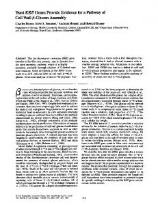
Figure 9: Accuracy rate of part retrieval for four databases under different parameter setting for λ1 and λ2 . 100 models, which includes about 1 h for co-segmentation, 1.5 h for computing contours and 2 h for training the classifiers. As an alternative, one can refine the evolving templates proposed by the method of Kim et al. [KLM*13]. We allow the creation of interesting variations by mixing the objects from different categories (sharing similar semantic labels). For example, a tabletop can sometimes be selected for the seat of a chair; or, the wings of a bird can be plugged onto an aeroplane’s body. In this section, we first evaluate the part retrieval aspect of our method and then the effectiveness of the system via a user study. A light weight demo is submitted as accompanying material. 7.1. Context-based part retrieval
Figure 8: Effect of local smoothness. In the source models, the transitions between the body and base are detected as smooth in models #1 and #2, but not in #3. Therefore in result #1, the smoothness is maintained by scaling the two parts being connected. In contrast, the connecting parts in result #2 are left unchanged.
Context-based part retrieval depends on two criteria (see Equation (1)): (i) consistency of geometric style between the retrieved part and the already-placed adjacent ones, and (ii) the consistency of the overall shape style between the parts. To evaluate the effect of the contextual information, we test the part retrieval of our system under different parameter settings of λ1 and λ2 in Equation (1) via a user study.
7. Result
For each database, we asked eight users to design new models using our system. For each user, we randomly select from the design sessions three retrieval scenarios each of which has at least three already placed parts serving as context. For each scenario, we let another eight participants to vote for the candidate parts (with the same category as the current one) from all the other models in the database on whether the candidate fits well with respect to the already placed parts, serving as a ‘ground truth’. Thus for each scenario, we obtain a consistent list through selecting the top 10 candidate parts based on the positive votes. If more than three of the top 10 retrieved parts in a scenario overlaps with its consistent list, we record it as accurate. The accuracy rate is computed with respect to all the scenarios selected for the database.
We collected a database consisting of 519 3D objects across eight categories for our system. These objects were dividfed into six subsets, where each contained semantically similar models. The six subsets were: chairs and tables (308 models, each containing two to five parts), aeroplanes and birds (48 models, five parts), vases (34 models, two to five parts), lamps (58 models, two to three parts), pavilions (32 models, two to three parts) and robots (39 models, five parts). It took roughly about 4 h to prepare a new category with
Figure 9 shows the accuracy rate for different database under different parameter settings of λ1 and λ2 . The chair database benefits most from the two contextual terms. This is possibly because chairs possess prominent geometric styles (in terms of both geometric details and overall shapes) making the contextual style consistency important. For lamps and vases, the accuracy gain is dominated by overall shape styles due to the lack of geometric details. For the aeroplanes, the contextual information plays a negligible role possibly
parts. Specifically, for a pair of connected parts, we compute a 2D contour for each part as the intersection between the part and a plane located at the contact point and perpendicular to the connecting direction. We then compare the area of the bounding boxes of the 2D contours. If the difference is smaller than a threshold (we use 1% of the sum of the two areas), we regard the connection as smooth. Finally, we connect the meshes along the cutting seam using mesh stitching [SBSCO06].
� C 2013 The Authors C 2013 The Eurographics Association and John Wiley & Sons Ltd. Computer Graphics Forum �
240
X. Xie et al. / Sketch-to-Design
Figure 10: Comparison of retrieved results with and without contextual information: (a) the reference model and its contours with user’s sketch, where the seat of chair has been fixed; (b) the ‘ground truth’ matching parts voted by eight participants; (c) the retrieved results according to only the user’s sketch, i.e. λ1 = λ2 = 0; (d) the results with λ1 = 1.0, λ2 = 0.0; (e) the results with λ1 = 0.0, λ2 = 1.0 a and (f) the results by considering both the user’s sketch and the full contextual information, i.e. λ1 = 0.5, λ2 = 0.5.
Figure 12: Compare with [LF08] on two modelling sessions. In the chair example (top), the user draws a sketch for seat part after the back part is fixed (1-a). Using the same sketch, both our method (1-b) and [LF08] (1-b’) retrieve a list of seat parts (only top three are shown) and the top candidate is selected for assembly. Likewise, the retrieval of leg parts uses the same sketch for both methods (1-c and 1-c’). The final results demonstrate that the chair modelled with our method (1-d) shows better style consistency than that by [LF08] (1-d’). The same result can also be observed in the lamp modelling. not indispensable or desirable, since user sketches often reflect only fuzzy cue of the user’s design intent. Figure 11: Two cases where context-aware placement does not assembly parts as expected. The lampshade is placed into the target lamp with the contextual information of the source lamp (a), missing the expected position indicated by the user’s sketch (red lines). This is due to the fact that the relative positions between lampshade and lampstand are different in the source and the target. Due to the same reason, the handle is misplaced in the target vase model in (b). because of negligible shape variations in the database. The relatively low percentages (50–70%) are due to the fact that sketch-based retrieval of a shape part is quite ambiguous, in contrast to whole shape retrieval [ERB*12]. Another reason is the ‘ground truth’ (obtained via voting by participants) itself contains ambiguity since different participants may have different preference for candidate parts. However, this is acceptable in practice for the design exploration task: It is often the case that very accurate part retrieval is actually
In Figure 10, we show the effect of the contextual constraints where we show the retrieval results for a back part of a chair model with the seat fixed under different parameter settings. When both constrained are disabled (λ1 = λ2 = 0), the retrieval results are affected only by the user’s sketches. Note that this setting emulates the sketch-only interface for part-based model synthesis as proposed by Lee and Funkhouser [LF08]. In contrast, when we enable the context terms (λ1 = λ2 = 0.5), the retrieved parts are more consistent with respect to the neighbouring parts and conform better to the user voted ‘ground truth’. 7.2. User experience We test the effectiveness of our interactive modelling system via a user study involving 16 participants. The group of users consisted of 3D modellers/artists, graduate students in graphics and non-graphics students (novice users), in roughly equal proportions. Before the
� C 2013 The Authors C 2013 The Eurographics Association and John Wiley & Sons Ltd. Computer Graphics Forum �
241
X. Xie et al. / Sketch-to-Design
Figure 13: Examples of the ‘Google challenge’ test. The reference photos are the top five search results from Google engine with the key words ‘chair’, ‘lamp’, ‘vase’ and ‘plane’, respectively. The objects in each image were modelled by the users using our system. The best result corresponding to each photo is displayed here. actual testing, participants were allowed to get familiar with the system under the guidance of our developers, typically under 15 min. We conducted two types of user studies: The first one is goaldirected modelling to test the effectiveness of our system in returning relevant parts in order to construct a model similar to the goal. The second one is free modelling where the user is allowed to freely design new models by exploring various part assemblies offered by our system. This tests the ability of our system in supporting the conceptual design of new 3D model. In all these tests, we set λ1 = λ2 = 0.5. Goal-directed modelling. Although our system is designed for open-ended modelling, in order to evaluate the performance of our retrieval module, we first conduct a goal directed modelling experiment. We give the users a collection of photographs containing the target object and ask them to build 3D models as similar to the targets as he/she can do. We have conducted a ‘Google challenge’: we used four key words ‘chair’, ‘lamp’, ‘vase’ and ‘plane’ to search for four categories of photos from the Google Image search engine. For each category, the top five returned images were presented to the used as the goals for modelling. The modelling results were crossrated among the participants. The top modelled shapes (according to the user scores) for each goal photo are in Figure 13. Additional user study results can be found in the accompanying material. In order to investigate the effect of the contextual part retrieval in the goal-directed modelling sessions, we record in Table 1 how many collected models were temporarily selected (number of mouse clicks by the user) during designing a new model. Two different parameter settings in Equation (1) are compared. As expected, modelling time is shortened by considering contextual information. Free modelling. In the second user study, we asked the 16 participants to freely create 10 different objects using our system. Here, the users are not provided any specific target as goal, except know-
Table 1: The average numbers of the temporarily selected models in the database for designing a new model under different retrieval strategies. Note that λ1 = 0 and λ2 = 0 indicate no contextual information is considered for the retrieval, and hence emulates the system by Lee and Funkhouser [LF08].
Objects
Chair + Table Table Aeroplane + Bird Lamp Vase Pavilion Robot
System parameters λ1 = 0, λ2 λ1 = 0.5, λ2 λ1 = 0, λ2 λ1 = 0.5, λ2 λ1 = 0, λ2 λ1 = 0.5, λ2 λ1 = 0, λ2 λ1 = 0.5, λ2 λ1 = 0, λ2 λ1 = 0.5, λ2 λ1 = 0, λ2 λ1 = 0.5, λ2 λ1 = 0, λ2 λ1 = 0.5, λ2
=0 = 0.5 =0 = 0.5 =0 = 0.5 =0 = 0.5 =0 = 0.5 =0 = 0.5 =0 = 0.5
Average clicks 15 9.5 8 6.5 13 11 10 8 13 10 11 7 15 11
ing the category to model. Figure 14 shows a portion of the modelling results produced by the various users. We note that the newly generated models contain a fair amount of variation from the original database models. According to their modelling experience, about 85% of the participants confirmed in questionnaire that they have significantly benefitted from the intermediate modelling suggestions and the ability to change viewpoint during modelling. Among the rest 15%, most preferred sketching all parts by hand than adopting the automatically suggested ones. In Figure 15, we show the part composition of four selected models from Figure 14.
� C 2013 The Authors C 2013 The Eurographics Association and John Wiley & Sons Ltd. Computer Graphics Forum �
242
X. Xie et al. / Sketch-to-Design
Figure 14: Selection of models created by users of our system. The less geometric variations in the database shapes, the less diversity in the visual words and the more shared visual words in their BOW features, which consequently means the search space resulted by the inverted indexing is denser (see Section 5.3). This is reflected by the relatively long retrieval time for data sets of vases and aeroplanes. Limitations. In Figure 11, we show examples where context-aware part placement failed to position the parts as hinted by the user’s sketch. This is due to the inconsistency of contextual information in the source and the target model, i.e. the source and the target have different relative positions between the part being placed and its neighbouring parts. Figure 15: Part composition of four selected models from Figure 14. In each model, the final result is shown in the middle with the colours indicating the sources of its composition parts. Table 2 shows the response time of retrieval and assembly per part. Since we use the inverted index structure, the running time on part retrieval for a shape category largely depends on the amount of geometric variations within that category of shapes in the database.
Furthermore, the current system is limited in its ability to create finer level of geometric textures (e.g. surface patterns) and microstructure assembly. Although such textures can possibly be suggested through context (e.g. a beamed chair seat is likely to have a matching beamed back), current sketching tools do not support their direct creation. Another limitation is the sequential modelling paradigm adopted in our system: Any time a part is sketched for retrieval and assembly, it subsequently becomes fixed and the whole
� C 2013 The Authors C 2013 The Eurographics Association and John Wiley & Sons Ltd. Computer Graphics Forum �
X. Xie et al. / Sketch-to-Design Table 2: Response time of retrieval and assembly in milliseconds on various data sets. The relatively long retrieval time for vases and aeroplanes is caused by insufficient shape variation in the data sets; see text for explanation.
Data set
Size
Retrieval
Assembly
Chair Table Chair+Table Lamp Aeroplane+Bird Vase Pavilion Robot
172 136 308 58 48 34 32 39
14 13 14 13 297 294 14 13
41 14 20 21 23 77 20 22
model is built sequentially. This design choice, however, allows us to trade-off between the exploration of design space and the ease of use. However, in the future, we will like to realize non-sequential modelling paradigm where the user can deal with multiple parts simultaneously, which may involve updating the neighbouring parts accordingly. The latter can again benefit from contextual information. Currently, including a new category into the system requires laborious effort on data preparation and pre-processing, which limits the scalability of our system. Finally, our system focuses on conceptual design and produces only approximate part assemblies via snapping guided by a small number of contact handles, and hence is not appropriate for more extended part connections (e.g. across seam lines). 7.3. Comparison We compare our system with an emulated implementation of the sketch-based part assembly system by Lee and Funkhouser [LF08] by turning off the contextual constraints in part retrieval. We compare the part style consistency for both methods. Figure 12 shows a comparison with two modelling sessions. For each method, we use the exactly same sketches for all parts and always choose the top retrieved part for assembly, only to demonstrate the power of contextual information in maintaining the style consistency among the parts. The results indicate that our method returns models with better style consistency.
243
is guided through the possible design space. We demonstrated the effectiveness of the system in both creative design (i.e. no pre-set design targets) and modelling from photo inspirations (e.g. remodel from Google Photos) via various user sessions. While various modelling systems exist (e.g. [FKS*04, KJS07, OFCD02, KCKK12]), comparing expressiveness and simplicity of use across the different systems remain a challenging task. A key bottleneck is different methods make different assumptions about input data sets (e.g. labelled vs. unlabelled; aligned vs. non-aligned; etc.) making it very difficult to fairly compare their advantages and disadvantages. In the future, we expect to have suits of benchmark tasks to rate different such modelling systems. A challenge, however, will be to measure the useability and aesthetic. With the growing accessibility of model collections and tools to automatically analyse, explore and handle such collections, we expect to see many data-driven modelling systems. An important direction to explore is to relate geometry to high-level object semantics and also bring in support for low-level texture and microstructural analysis. Ideally, the rich knowledge learned from the database can serve as the ‘mind’s eye’ for the design system. A true creative design should allow us to go beyond conventional forms and semantics, to achieve a new level of aesthetics and comfort. For example, a conceptual chair may simply be created out of a few wires, disrespecting the usual functional or semantical decompositions. In the future, we want to bridge this gap in an effort to better support creative design in the early stages of conceptual design.
Acknowledgements This project was supported by the National Natural Science Foundation of China (61202223, 61232011, 61202222), Guangdong Natural Science Foundation (S2011040000433), National 863 Program (2012AA011801) and Shenzhen Innovation Program (CXB201104220029A, ZD201111080115A, KC2012JSJS0019A). Special thanks to Mr. Kangxue Yin and Mr. Lingxiao Yang who have devoted their contributions to the coding of this project.
References [CK10] CHAUDHURI S., KOLTUN V.: Data-driven suggestions for creativity support in 3D modeling. In Proceedings of ACM SIGGRAPH Asia (Seoul, South Korea, 2010), vol. 29, pp. 183:1–10.
8. Conclusion We presented an interactive sketch-to-design system where user provided 2D strokes are used to enable data-driven navigation of design spaces comprising of part-based model variations. For each sketched part, the system suggests plausible 3D shape candidates based on curved-based matching as well as contextual cues, which are extracted from model collections (e.g. models from Google 3D Warehouse). Inspired by recent success of assisted sketching systems like ShadowDraw, we support 3D modelling that continuously provides design suggestions to the users based on the input strokes. The user can freely change viewpoints during the design session. Retrieved parts are deformed, positioned and connected to the existing model, again based on context information, as the user implicitly
[CKGK11] CHAUDHURI S., KALOGERAKIS E., GUIBAS L., KOLTUN V.: Probabilistic reasoning for assembly-based 3D modeling. In Proceedings of ACM SIGGRAPH (Vancouver, Canada, 2011), vol. 30, ACM, pp. 35:1–10. [CTSO03] CHEN D.-Y., TIAN X.-P., SHEN Y.-T., OUHYOUNG M.: On visual similarity based 3D model retrieval. Computer Graphics Forum (Proc. Eurographics) 22, 3 (2003), 223– 232. [DFRS03] DECARLO D., FINKELSTEIN A., RUSINKIEWICZ S., SANTELLA A.: Suggestive contours for conveying shape. In Proceedings of ACM SIGGRAPH (Santiago, Chile, 2003), pp. 848–855.
� C 2013 The Authors C 2013 The Eurographics Association and John Wiley & Sons Ltd. Computer Graphics Forum �
244
X. Xie et al. / Sketch-to-Design
[ERB*12] EITZ M., RICHTER R., BOUBEKEUR T., HILDEBRAND K., ALEXA M.: Sketch-based shape retrieval. ACM Transactions on Graphics (Proc. SIGGRAPH) (2012), 31, 31:1–31:10. [FH10] FISHER M., HANRAHAN P.: Context-based search for 3D models. ACM Tranactions on Graphics (Proc. SIGGRAPH Asia) 29, 6 (December 2010), 182:1–10. [FKS*04] FUNKHOUSER T., KAZHDAN M., SHILANE P., MIN P., KIEFER W., TAL A., RUSINKIEWICZ S., DOBKIN D.: Modeling by example. In Proceedings of ACM SIGGRAPH (Los Angeles, CA, USA, 2004), pp. 652–663. [FMK*03] FUNKHOUSER T., MIN P., KAZHDAN M., CHEN J., HALDERMAN A., DOBKIN D., JACOBS D.: A search engine for 3D models. ACM Transactions on Graphics 22, 1 (January 2003), 83–105. [FSH11] FISHER M., SAVVA M., HANRAHAN P.: Characterizing structural relationships in scenes using graph kernels. ACM Transactions on Graphics 30, (August 2011), 34:1–12. [HKG11] HUANG Q., KOLTUN V., GUIBAS L.: Joint shape segmentation using linear programming. ACM Transactions on Graphics (Proc. SIGGRAPH Asia) 30, 6 (December 2011), 125:1–11. [JTRS12] JAIN A., THORMA¨ HLEN T., RITSCHEL T., SEIDEL H.-P.: Exploring shape variations by 3D-model decomposition and partbased recombination. Computer Graphics Forum (Proc. Eurographics 2012) 31, 2 (2012), 631–640. [KCKK12] KALOGERAKIS E., CHAUDHURI S., KOLLER D., KOLTUN V.: A probabilistic model of component-based shape synthesis. ACM Transactions on Graphics 31, 4 (2012), 55:1–11. [KHS10] KALOGERAKIS E., HERTZMANN A., SINGH K.: Learning 3D mesh segmentation and labeling. In Proceedings of ACM SIGGRAPH (Los Angeles, CA, USA, 2010), pp. 102:1–12. [KJS07] KREAVOY V., JULIUS D., SHEFFER A.: Model composition from interchangeable components. In Proceedings of Pacific Graphics (Maui, Hawaii, USA, 2007), pp. 129–138. [KLM*13] KIM V. G., LI W., MITRA N. J., CHAUDHURI S., DIVERDI S., FUNKHOUSER T.: Learning part-based templates from large collections of 3D shapes. ACM Transactions on Graphics (Proc. SIGGRAPH) 32, 4 (2013), 1–12. [LF08] LEE J., FUNKHOUSER T.: Sketch-based search and composition of 3D models. In EUROGRAPHICS Workshop on Sketch-Based Interfaces and Modeling (Crete, Greece, June 2008). [LZC11] LEE Y. J., ZITNICK L., COHEN M.: Shadowdraw: Realtime user guidance for freehand drawing. ACM Transactions on Graphics (Proc. SIGGRAPH) 30, 4 (July 2011), 27: 1–9. [MGP06] MITRA N. J., GUIBAS L. J., PAULY M.: Partial and approximate symmetry detection for 3D geometry. ACM Transactions on Graphics (Proc. SIGGRAPH) 25, 3 (July 2006), 560–568.
[MHTG05] M¨ULLER M., HEIDELBERGER B., TESCHNER M., GROSS M.: Meshless deformations based on shape matching. ACM Transactions on Graphics (Proc. SIGGRAPH) 24, 3 (2005), 471–478. [OFCD02] OSADA R., FUNKHOUSER T., CHAZELLE B., DOBKIN D.: Shape distributions. ACM Transactions on Graphics 21 (October 2002), 807–832. [OLGM11] OVSJANIKOV M., LI W., GUIBAS L., MITRA N. J.: Exploration of continuous variability in collections of 3D shapes. ACM Transactions on Graphics (Proc. SIGGRAPH) 30 (August 2011), 33:1–10. [PKM*11] PACZKOWSKI P., KIM M. H., MORVAN Y., DORSEY J., RUSHMEIER H., O’SULLIVAN C.: Insitu: Sketching architectural designs in context. ACM Transactions on Graphics (Proc. SIGGRAPH Asia) 30, 6 (2011), 182:1–10. [SBSCO06] SHARF A., BLUMENKRANTS M., SHAMIR A., COHEN-OR D.: Snappaste: An interactive technique for easy mesh composition. In Proceedings of Pacific Graphics (Taipei, Taiwan, 2006), pp. 835–844. [SFCH12] SHEN C.-H., FU H., CHEN K., HU S.-M.: Structure recovery by part assembly. ACM Transactions on Graphics (Proc. SIGGRAPH Asia) 31, 6 (2012), 180:1–11. [SI07] SHIN H., IGARASHI T.: Magic canvas: Interactive design of a 3-D scene prototype from freehand sketches. In Proceedings of Graphics Interface (Montreal, Canada, 2007), pp. 63–70. [SvKK*11] SIDI O., VAN KAICK O., KLEIMAN Y., ZHANG H., COHENOR D.: Unsupervised co-segmentation of a set of shapes via descriptor-space spectral clustering. In Proceedings of ACM SIGGRAPH Asia (Hong Kong, China, 2011), pp. 126:1–9. [SXY*11] SHAO T., XU W., YIN K., WANG J., ZHOU K., GUO B.: Discriminative sketch-based 3D model retrieval via robust shape matching. Computer Graphics Forum 30, 7 (2011), 2011–2020. [SZ03] SIVIC J., ZISSERMAN A.: Video Google: A text retrieval approach to object matching in videos. In Proceedings of IEEE ICCV (Nice, France, October 2003), vol. 2, IEEE Computer Society, pp. 1470–1477. [WMB99] WITTEN I. H., MOFFAT A., BELL T. C.: Managing Gigabytes: Compressing and Indexing Documents and Images. Morgan Kaufmann Publishing, San Francisco, CA, USA, 1999. [XCF*13] XU K., CHEN K., FU H., SUN W.-L., HU S.-M.: Sketch2scene: Sketch-based co-retrieval and co-placement of 3D models. ACM Transactions on Graphics (Proc. SIGGRAPH) 32, 4 (2013), 123:1–123:15. [XLZ*10] XU K., LI H., ZHANG H., COHEN-OR D., XIONG Y., CHENG Z.-Q.: Style-content separation by anisotropic part scales. In Proceedings of ACM SIGGRAPH Asia (Seoul, South Korea, 2010), pp. 184:1–10.
� C 2013 The Authors C 2013 The Eurographics Association and John Wiley & Sons Ltd. Computer Graphics Forum �
X. Xie et al. / Sketch-to-Design
[XZCOC12] XU K., ZHANG H., COHEN-OR D., CHEN B.: Fit and diverse: Set evolution for inspiring 3D shape galleries. ACM Transactions on Graphics (Proc. SIGGRAPH) 31, 4 (2012), 57: 1–10.
245
[ZS84] ZHANG T. Y., SUEN C. Y., : A fast parallel algorithm for thinning digital patterns. Communications of the ACM 27 (March 1984), 236–239. Supporting Information
[ZCOM13] ZHENG Y., COHEN-OR D., MITRA N. J.: Smart variations: Functional substructures for part compatibility. Computer Graphics Forum (Proc. Eurographics) 32, 2 (2013), 195–204.
Additional Supporting Information may be found in the online version of this article at the publisher’s web site: Video S1:
� C 2013 The Authors C 2013 The Eurographics Association and John Wiley & Sons Ltd. Computer Graphics Forum �
Copyright of Computer Graphics Forum is the property of Wiley-Blackwell and its content may not be copied or emailed to multiple sites or posted to a listserv without the copyright holder's express written permission. However, users may print, download, or email articles for individual use.