Switching Systems Software Development ... design of finite-state automata and for the generation ... o logical (software) signals corresponding to the (hard-.
1356
IEEE TRANSACTIONS COMMUNICATIONS, ON
VOL. COM-30, NO. 6 , JUNE 1982
sL1 Language-A Specification and Design Tool for Switching Systems Software Development MATIJA EXEL, BRANISLAV T. POPOVIC, AND FRANCEK PRIJATELJ
Abstrucr-The
paper presents a new programming languagethe specificationanddesign language4esigned as a development tool for the Iskra 2000 multimicroprocessor telephone exchange software system [4], SLl is a concise and simple language used for the specification and of thecordesign of finite-stateautomataandforthegeneration responding tables. The languageismodularandstructured, with control constructs inspired by the CCITT CHILL, only compile-time var.iables,simplemacroprocessingfacilities,andmodestpreprocessing facilities.
SLll finite-stateautomata
-RECEPTION -TREATMENT *GENERATION
LOCAL SIGNALS
LOGICAL SIGNALS .RECEPTION .TREATMENT GENERATION
LOCAL SIGNALS
0
1 TELEPHONE
I. INTRODUCTION
A
N important part
of an exchange softwaresystemconsists of thespecificationand design of finite-state automata,which are neededfortheinterpretationof various signals at different semantic levels: o physical signals occurring in the terminalsensor points, o logical (software) signals corresponding to the(hardware) sense point state changes, and o telephone signals, which correspond to different sequences and different lengthsof logical signals. The automata may therefore be classified, like signals that they interpret, in three levels: physical, logical, and telephone level. The interpretation function of an automaton at a given level may be viewed as consisting of the following three steps: o reception of signals; o treatment of signals-in theautomata of thefirst two levels the treatment of incoming signals mainly involves the recognition of hlgher level signals; o generation of signals of the next higher level, when applicable. 'This hierarchical view is schematically captured sin Fig. 1. The local signals are explained later. ,Automata are usually graphically representedbystate transition graphs (or diagrams). The elements of a state transition graphare 0 nodes, which represent automata states, ahd e directed arcs, each of which is labeled with an event (signal), whichmayoccur(be received) in the predecessor state and e an action sequence (treatment and generation), which is executed upon the event occurrence. The last execui.ed action of this sequence indicates the transition t o the successor state. Manuscript received October 20, 1981; revised December 31, 1981.
M. Exel and F. Prijatelj are with the Department of Computer Science, Institut Joief Stefan, Jamova 39,61000 Ljubljana, Yugoslavia. B. T. PopoviE is with the ATC Technical Development Department, Iskra Telematika, 64000 Kranj, Yugoslavia.
.RECEPTION
LOCALSIGNALS
.TREATMENT '
1
E51AS5
SlGNALS
Fig. 1.
in s 1 : when E l : d o AS1, newstate is S2 when E2: d o AS2, newstate is s 2 in s 2 : when E3: do AS3, newstate is s 3
A35/!/,
in s3: E4/AS4
when E4: d o AS4, newstate is S3 when E5 : do AS5, newstate is S1
Fig. 2.
To describe automatawitha programming language we need,however,alinearrepresentation. We have chosen the simplest one corresponding to the above graphical representation. An example is given in Fig. 2. Aswe willsee in the following, the SL1 language's basic building block (the signaling or automaton definition module) closely corresponds to the above linear representation. The eventsof an automaton may be classified as e external events-these eventsaregeneratedoutsidethe automaton and are, from the point of view of the given automaton, occurring asynchronously (example: the external events-logical signal-of A2 of Fig. 1 are generated byAI); 0 internalor local events-these are (software)events generated w i t h the action sequences of the automaton and are occurring synchronously. In SL1 we may similarly representbothkinds of events (see Sections 111-C and 111-H). The second section introduces the' SLl approach, the third section describes the language, thenext outlines the SL1 compiler, and the last presents a conclusion.
0090-6778/82/0600-1356$00.75 0 1982 IEEE
11. SLl APPROACH
tions, and macro definitions. The executive part is a sequence The SL1 language [ 11 -131 is both a specification and a of signaling definition calls; this sequence specifies a set of design (implementation) language. It has been designedas a independentautomata to be translated intothe associated developmenttoolforthe Iskra 2000 multimicroprocessor automata tables. The syntax: telephone exchange software system [4]. Thepresentsection describes themostimportantSL1 (sL1 pxogram): :={(macro definitiodl language design decisions. (subroutine definition)I The starting point for the SL1 language has been the linear (signaling definition))" representation of Fig. 2. All other features of SL1 are essen[BEGIN; tially the well-known programminglanguage features. {(signaling call)), * Our main intent has been to produce a simple and concise END] language, which would permit one to capture the automaton logic down to the level of action sequences of Fig. 2. For the (signaling c a : :=(signaling name)[({(sig. argument)[,}I*)] ; reasons of efficiency and modularity we have, however, deEachSL1modulein the declarative part is syntactically cided to add macros and subroutines. The three kinds of pro- analyzed and, if correct, copied into the corresponding module gram modules that emerged were, thus: the automaton (signal- fie. Each called SL1 module in the executive partis extracted ing) module, the subroutine module, and the macro module. from its module file and macroexpanded, preprocessed, and Most oftheelementaryactions,whichconstitutethe translated in a code form (automata table) suitable for interactionsequences, have been already available from previous pretation in a run-time system. systemsand have been coded as assembler subroutines.To This modularapproach allows for the translation of any shortentheSL1development, we have decided thatthe combination of independent automata-the combinationbeing automaton logic, encompassed by action sequences, should be dependentontheapplicationsystem to be built-intothe based on these elementary actions; therefore, the elementary associated automata tables. actions constitute the basic SL1 statements. As the elementary An example SL1 program isgiven in the Appendix. actions contain all data manipulations, we have felt that there In the following we will present an overview of the SL1 would be no further need for variables and operations upon program elements and, with somewhat more detail, the most variables; SL1 features only compile-time variables (run- characteristic language features. time constants). Two features have been present from the very beginning of B. Overview of the SLl Program Elements the language inception:the possibility of parameterizing 1) Definitions of Modules and Compile-Time Variables: automata definitions and the possibility of conditional com- Theprogrammodules are introducedwiththe following pilation (by preprocessing): In effect, a lot of automata are definitions. quite similar; both features should therefore reduce the 0 signaling definition: amount of programming. SIGBEGIN signalingname (optional parameters); Let us sum up: SL1 is a concise and simple language used declarations and local subroutines for the specificationand design of finitestate automataat ... different semantic levels and for the generation of the correSIGEND; sponding automata tables. The language is modular and struc0 macrodefinition: tured, with control constructs inspired by the CCITT CHILL [SI, onlycompile-time variables, simple macroprocessing MACBEGIN macro-name; facilities, and a modest preprocessing facility. The automata declarations ... tables correspond to the automata states, the events occurring in a given state, and the actions,whichare to be executed MACEND; upon an event occurrence. In an on-linesystemthesetables Macro parameters are positional and are implicitly declared are interpreted. by their appearance in the body of a macro definition. Macro A short discussion of the SL1 approach is included in the parameters are denoted by %i (1 < i < 9), where i specifies conclusion. the position. Types (INT or BOOL or string) of macro parameters are determined contextually by the semanticanalysis. 111. LANGUAGE DESCRIPTION 0 subroutinedefinition: '
The syntax conventions are those of the CHILL
VI
language
*
A. SLI Program An SLl program comprises twoparts:a declarative part and an executive part. The declarative part is a sequence of independentmodule definitions.There are threekindsof modules: signaling (automaton) definitions, subroutine defini-
SUBEGIN subroutine-name; declarations
...
SUBEND; Subroutines are local or global; local subroutines can only be local to signaling definitions. Compile-time variables are introducedwithdeclaration statements and can be of type INT or BOOL.They are always
initialized by means of compile-time expressions. The scope of a variable is the module in which the variable is declared. The variables declared in a signaling definition arealso known within the local subroutines of the signaling definition. Ciompile-time expressions can involvepreviously declared compile-time variables, constants, signaling parameters,and macro parameters (in macro definitions). Integer expressions are used in variable initializations, as repetitionfactors of loops, as elements of value lists in CASE statements,etc. Boo:lean expressions are used onlyin variable initializations and as conditions of preprocessor statements. 2) Elementary Actions and ElementaryConditions: Elementary actions are the basic statements of SL1programs. An elementary action is just an action name followed- by a semicolon. Such a basic statement is in fact a no-parameter procedure call. Actionnames are reserved and globally known names for predefinedprocedures to becodedoutside the SL1 language. Elementary conditions (condition names) arelikewisereserved and globally known names for predefined Boolean or integer functions. Condition names are used in I F statements (Boolean valued conditions) and in CASE statements (integer valued conditions). 3) ControlActions: These arethe familiar controlstatements: 0 IF-THEN-ELSIF-ELSE-FI statement, 0 CASE-ESAC statement, 0 DO-OD finite and infinite loops, EXIT, NEXT and RETURN statements, 0 MCALL macro call statement, 0 CALL subroutine call statement and the signaling call statement. 4) Preprocessor Action: Only one form of preprocessor statement is available: a static (compile-time) I F statement: CIF compile-time-Boolean-expression CTHEN-CELSIF-CELSE-CFI statement. 5) Special Actions: There is finally a set of special, switching systems oriented statements: the SETSTATE statement is used forsettingthestate of the automaton ina signaling definition; the WAIT statement is used for delays, timeouts, and for the identification and generationof pulse signals; the PUT and GET statements are used for data transfer and, indirectly, for interautomatacommunication.
Change of state actions are not allowed within global subroutines; they are allowed within local subroutines. Signaling definitions can be parameterized by integer and Boolean parameters.Thecorresponding argument valuesare specified at the signaling definition call. The following signaling definition may correspond t o the automaton graph of Fig. 2. SIGBEGIN AUTOMATON; STATE 1: EVCASE /* event CASE statement */ EVENT 1 : AS 11;/* elementary action */ AS12; SETSTATE 2 ;/* transfer to state 2 *I EVENT 2: AS21 ; AS22; SETSTATE 2; EVESAC ; STATE 2: EVCASE EVENT 3: AS3 ; SETSTATE 3 ; EVESAC ; STATE 3 : EVCASE EVENT 4: AS41 ; AS42; SETSTATE 3 ; EVENT 5: AS5; SETSTATE 1 ; EVESAC ; SIGEND; State numberswithin a signaling definitionandevent numbers within a given state must be different; same event numbers may occur in different states.
D. Wait Statements Wait statements are used for delays, timeouts,for pulse signal identificationwithorwithoutthe presence of noise, and forpulse signal generation. The syntax:
C.Signaling Definition
(wait action): :=WAIT (time),(period) [ [ ,(filter)] ,(state)] ; (time),(period): :=(static integer expression)( I S IMS IMIN} (filter)::=FILTER (static integer expression){lS IMS IMIN} (state): :=STATE (static integerexpression)
Each signaling definition is a description of an independent automaton.Thestatesoftheautomaton are introducedby state labels (STATE followed by an integer value). The events which can occur in a given state are introduced by event labels (EVENTfollowed byaninteger value). Each event label labels an action sequence to be executed upon occurrence of the associated event; such an action sequence must be dynamically terminated by a change of state action (WAIT statement with STATE part-seebelow-or more usually a SETSTATE statement) which specifies thenextautomatonstate. This dynamic termination of event action sequences is checked by the compiler.
Time is the total delay duration; period is the measuring time quantum (timing rate); time units are seconds, milliseconds,andminutes;filter is thetolerated noise duration. At least one time unit must be specified; to an element (time, period, or filter) with no time unit specified, the first specified time unit is applied. We distinguish three kinds of wait statements: noninterruptible, interruptible, and filtered wait statements. 1) Nonintermptible Wait Statement: This is a simple delay statement (no filter part,no state part). Anyevents which may occur during the delay are suspended untiltheendofthe delay.
1359
EXEL et ai.: SLI LANGUAGE-SPECIFICATION AND DESIGN TOOL
?-7
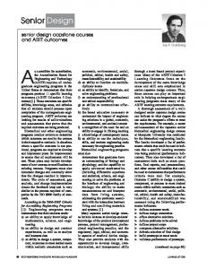
70 MS
LENGTH IS 220 MS
1 - 7
__.._
400 MS
40 MS
40 MS
1
Fig. 3.
70 MS
30 MS 20 MS
20 MS Fig. 4.
I. 40 MS
Example: the generation of the signal in Fig. 3 is expressed* in SL1 as follows: following SLl automaton: START-SIGNAL; WAIT 20 MS, 10; STOP-SIGNAL; WAIT 40 MS, 10; START-SIGNAL; WAIT 70 MS, 10; STOP-SIGNAL; WAIT 100 MS, 10; 2) Interruptible Wait Statement: An event whichmay occur during the timeout, specified by an interruptible wait statement, is immediately accepted: the timeout is cancelled and the automaton proceeds to the state specified by STATE and the event is considered to have occurred in this new state. Interruptible wait statements areused for pulsesignal identification and for timeouts. Example of a wait statement used for timeout: SIGBEGIN CALLING-SUBSCRIBER; DCL INT HOOK-OFFz3, DIGlT=4, IDLE=l, DIALING=2, PARKING=3; STATE IDLE: EVCASE EVENT HOOK-OFF: DRIVE-DIAL-TONE; /*elementaryaction*/ WAIT 30 S,l S, STATE DIALING; /*timeout till dialing*/ DRIVE-PARKING-TONE; SETSTATE PARKING; EVESAC; STATE DIALING: EVCASE EVENT DIGIT: . I .
SIGEND ;
SIGBEGIN SIGNAL; STATE 1: EVCASE EVENT 1: /*signal from ci to 1 */ WAIT 40MS, 10, STATE 1; WAIT (500 -40)MS, 10, FILTER 40, STATE 2; ACCEPT-INFINITE-SIGNAL; SETSTATE 1 ; EVENT 2 : /* signal from 1 to 0 */ SETSTATE 1 ; EVESAC ; STATE 2 : EVC ASE EVENT 2: ACCEPTJOOMS-SIGNAL; SETSTATE 1; EVESAC ; SIGEND ; E. Macro Definition Themacros are defined on the signaling definition level, which means that a macro body may contain state and event labels and EVCASE statements. A simple example of a macro: MACBEGIN RINGING; DO %1/(%2 1); START-RINGING; WAIT lS,lOOMS,STATE RINGING; STOP-RINGING; WAIT %2 S,100OMSSTATERINGING; OD ; MACEND;
+
the call MCALL RINGING(60,2);
3) Filtered Wait Statement: This type of wait statement is used for pulse signal identification. The semantics of filtered wait statement is similar tothat of the interruptible wait statement with the following additional provision: during the delay duration there may be tolerated spans of signal absence, each of themwiththemaximumduration specified in the filter part of the statement. If the signal absence span is less than the filter-specified duration, it is ignored; otherwise it is interpreted as an event which interruptsthe delay andthe automaton proceedsto a new state as in the previous case. Example: a signal of 500 ms (more exactly: 40 ms< signal length