SL2SX Translator: From Simulink to SpaceEx Models Stefano Minopoli
Goran Frehse
VERIMAG Centre Équation - 2, avenue de Vignate 38610 GIÉRES
VERIMAG Centre Équation - 2, avenue de Vignate 38610 GIÉRES
[email protected]
ABSTRACT The tool Matlab/Simulink is a numerical simulation environment that is widely used in industry for model-based design. Numerical simulation scales well and can be applied to systems with highly complex dynamics, but it is also inherently incomplete in the sense that critical events or behavior may be overlooked. The application of formal verification techniques to Simulink models could help to overcome this limitation. Set-based verification tools such as SpaceEx use as underlying formalism hybrid automata, which are semantically and structurally different from Simulink models. To address this issue, we are building the tool SL2SX for transforming a subset of the Simulink modeling language into a corresponding SpaceEx model. Our method is designed to preserve the syntactic aspects of a given Simulink diagram: the resulting SpaceEx model shows the same hierarchical structure and preserves the names of components and variables. Placeholders with the correct interface are provided for unsupported Simulink blocks, which can then be translated manually. We illustrate the tool SL2SX and the verification of the transformed models in SpaceEx on two examples provided by the Mathworks example library.
1. INTRODUCTION Matlab/Simulink [17] is a software tool widely used in industry to model and simulate physical systems. For modeling, it provides a set of standard blocks from which one can hierarchically create a block diagram of the system. For simulating, it provides an extensive library of solvers, each of which determines the time of the next simulation step and applies a numerical method to solve the set of ordinary differential equations arising from the model. Different from simulation, formal verification can provide complete coverage, and hence it can be used to ensure whether or not a model meets a requirement. To apply formal verification techniques, it is necessary to switch from a simulation model to a verification model. Such a transformation needs to take into account the inherent differences between the two classes
Permission to make digital or hard copies of all or part of this work for personal or classroom use is granted without fee provided that copies are not made or distributed for profit or commercial advantage and that copies bear this notice and the full citation on the first page. To copy otherwise, to republish, to post on servers or to redistribute to lists, requires prior specific permission and/or a fee. HSCC 2016 Vienna, Austria Copyright 20XX ACM X-XXXXX-XX-X/XX/XX ...$15.00.
[email protected]
of models. Typically, a simulation model contains details that need to be abstracted away for the verification model. A verification model can be enriched with nondeterminism to check the system behavior for a whole range of parameters, disturbances, user inputs, etc. Simulink uses must semantics, also called urgent or ASAP semantics, meaning that a transition must be taken as soon as its guard is satisfied. Verification models, such as hybrid automata (HA), are typically defined with may semantics, in which the system can delay the transition as long as the invariant (staying condition) is satisfied. This may affect the quality of the model transformation, resulting in overapproximations, and the complexity of the model, resulting in state space explosion. Simulink lacks an actual formal description of its semantics. For the basic blocks one can resort to their ideal mathematical interpretation, but a wide variety of complex blocks is included in the standard Simulink library, many of which are beyond direct translation to functional models such as hybrid automata. Clearly, the process of translating a Simulink diagram into a verification model is not an easy task, and a fully automatic approach seems to be not plausible. Verification tools like SpaceEx [10] use Hybrid Automata (HA) [11] as models and check safety properties using reachability algorithms. Our goal is to make the tool SpaceEx applicable to Matlab/Simulink models. The SpaceEx verification language is able to preserve the structure and the hierarchy of a Simulink diagram, using basic and network components (a single hybrid automaton and a network of them, respectively). Preserving the structure of the simulation model is not just a secondary aspect because, as described in [26], the structure has a profound impact on several aspects of safety-critical model development. In this paper, we present the tool Simulink to SpaceEx Translator (SL2SX) that takes a Simulink model (in xml format) as input, and generates a network of hybrid automata in a format compatible with SpaceEx verification tool. Since the SX format closely resembles the mathematical definition of hybrid automata (modulo template and parameter instantiations), SX models can be automatically translated for other verification tools based on hybrid automata. The HyST translation tool [4] provides translations from SX to the verification tools Flow* [7], dReach [12], HyCreate [3], and HyComp / HyDI [9]. Our translation is based on the ideal interpretation of Simulink semantics [14]. The translation preserves all structural aspects of the Simulink diagram. Moreover, the translator preserves the names of blocks, variables, and compo-
nents, as well as the graphical positions and dimensions of blocks. The must semantics of Simulink are handled by enhancing SpaceEx with urgent conditions [21]. A restriction of our approach is that SpaceEx is currently limited to piecewise constant and piecewise affine dynamics. The translation process of SL2SX is not fully automatic, meaning that the SpaceEx model needs to be completed manually by adding hybrid automata to model blocks for which no translation is given. The tool aids in the completion process by adding placeholders with proper interface for the missing blocks. Having the mechanical aspects of the model transformation being carried out by a tool reduces errors and results in a model that can be easily compared with the Simulink diagram, due to the preservation of structure and names of blocks and variables. The tool SL2SX together with models in this paper are available online [20]. A variety of different approaches to verify Simulink models has been reported in literature. The tools HyLink [15] and GreAT [1] translate a Simulink diagram into hybrid automaton expressed by intermediate formats (i.e. hybrid input/output automata (HIOA) [22] and hybrid system interchange format (HSIF) [24], respectively). Both formalisms are not able to model hierarchy and must semantics. The tool Checkmate [23] provides a Simulink toolbox containing additional blocks that the designer is allowed to use. A Simulink model thus obtained is then translated into the special class of Polyhedra Invariant Hybrid Automata (PIHA) [8]. The PIHA formalism uses ordinary differential equations (ODE) to express the dynamics, hyperplanes for guard transitions and only identity as update functions. Hierarchy can not be handled, and moreover the PIHA may semantics cause overapproximation when modeling must transitions. Other formalisms than hybrid automata are also used. In [25], the discrete part of a Simulink model is translated to a pushdown automaton defined by the SAL transition system language [5], while the differential equations arising from the Simulink component are converted into difference equations. The resulting model is a discretization of the original. The tool S2H [28] translates Simulink models into the Hybrid CSP (HCSP) formalism [13], based on the separation of variable definitions, process definitions, assertion definitions and goals to be proved. This results in a loss of compositional properties and the obtained model may be hard to compare with the original. The tool HySon [6], performs set-based simulation with “imprecise” or “uncertain” inputs directly on a Simulink model. The aim is to compute a good approximation of the set of all possible Simulink executions. Being based on numerical simulation methods, HySon is able to handle systems with both nonlinear dynamics and guards, and zero-crossing events are properly treated. We expect that for certain classes of systems, SpaceEx, whose algorithms are highly optimized for piecewise affine dynamics, can outperform the more general algorithm of HySon. A direct comparison is not possible since HySon is not publicly available.
2. SIMULINK, HYBRID AUTOMATA AND SPACEEX We briefly introduce the modeling language of Simulink, the formalism of hybrid automata and the SpaceEx verification tool, highlighting the features relevant to the translation process.
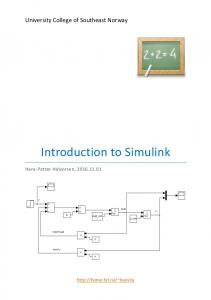
Figure 1: A Matlab/Simulink block diagram
2.1
Simulink Models
Simulink is an environment for simulation and modelbased design for dynamic and embedded systems. It provides an interactive graphical environment and a customizable set of blocks that let one design, simulate, implement, and test a variety of time-varying systems. The modeling language lacks a formal and rigorous definition of its semantics, usually estimated by either the ideal or the numerical simulation interpretation [14]. A Simulink design is represented graphically as a diagram consisting of inter-connected Simulink blocks. It represents the time-dependent mathematical relationship between the inputs, states, and outputs of the design. Figure 1 depicts an example of Simulink diagram, whose signal that drives the switch blocks is modeled by the hybrid dynamics x˙ = c + u, when x ≥ 0, and x˙ = c otherwise (where x is the integrator output). The follows definition derives from [2]. A Simulink model SL = ⟨D, B, C⟩ consists of the following components: • A set D of variables, partitioned into input variables DI and output variables DO . • A set B of Simulink blocks. Each block b ∈ B has inputs, outputs, and parameters. The input and output variables are associated with input and output ports. A Simulink block can be itself a Simulink Diagram; such a block is called a subsystem. • An ordered relation C ⊆ B × B represents connections between blocks. A connection c = ⟨b, b′ ⟩ ∈ C connects an outport of b with an inport of b′ and represent the flow of the data between the corresponding variables of b and b′ . Simulink uses must semantics, meaning that discrete events happen as soon as possible a given condition (guard) is satisfied (also referred as urgent or as-soon-as-possible (ASAP) semantics).
2.2
Hybrid Automata
Hybrid automata [11] are a verification modeling formalism that combines discrete states (modeled by locations) with continuously evolving, real-valued variables. The discrete states and the transitions from one state to another are described with a finite state-transition system. A change in discrete state can update the continuous variables and modify the set of differential equations that describes how variables evolve with time. Hybrid automata are nondeterministic, which means that different futures may be available from any given state. Rates of change or variable updates can be described by providing bounds instead of fixed numbers. Incomplete knowledge about initial conditions, perturbations, parameters, etc. can easily be captured in this way. A specific source of nondeterminism is due to the may semantics.
(a) Simulink subsystem (a) network component
(b) HA for “constant”
(c) HA for “integrator”
(d) HA for “sum”
(e) HA for “switch”
(b) SX component
Figure 3: The translation from a Simulink subsystem to an SX component preserves the interface be connected by binding their variables to the same symbols in B. Because of the acausal semantics, the variables binding does not distinguish source and destination (nonoriented connection). Figure 2(a) depicts a SpaceEx model of the Simulink model in Figure 1, whose components are the hybrid automata in Figures 2(b)–2(e). Formally, a SpaceEx model SX = (Comp, Bind) has
Figure 2: SpaceEx model for the Simulink diagram in Figure 1
• a set Comp of SpaceEx components, partitioned into the set Compb of basic components and the set Compn of network components. Each component b ∈ Comp has a set of formal parameters, including a set of variables V arb . For lack of space, we omit the discussion about synchronization labels and local variables.
This means that a transition may happen at any time the associated guard is satisfied, but it may also be delayed as long as the invariant (staying condition) of the discrete state is satisfied. Hybrid automata with urgency conditions allow the definition of a urgency condition for each location. A must transition can be easily encoded by adding its guard as urgent condition to the source location. For the class of LHA, an exact reachability algorithm is available [21].
• a relation Bind ⊆ Compn ×Comp that associates each network component with a set of components (including other networks components). Each variable of a component associated to a network, is also a variable of the network. For each (n, c) ∈ Bind, a mapping M apn,c : V arc → V arn associates to each basic variable a network variable.
2.3 SpaceEx
3.
FROM SIMULINK TO SPACEEX
SpaceEx is a development platform for verification algorithms based on hybrid automata. of a system, modeled by the SpaceEx definition language. The SpaceEx verification engine provides specific reachability algorithms, called scenarios, and each of them may come with its own set representation, apply to its own class of models, and produce a different kind of output. The scenarios include a formally exact algorithm for piecewise constant dynamics (PHAVer), two variations of template-based approximate reachability algorithms for piecewise affine dynamics (LGG and STC), and a simulation algorithm that mimics reachability analysis by random sampling of the initial states. A SpaceEx model is similar to the standard hybrid automata, syntactically extended with hierarchy and templates. A SpaceEx model consists of one or more components. Each component has a set of formal parameters, like continuous variables, constants, and synchronization labels. A formal parameter is part of the interface of a component, unless it is declared as local to the component. There are two types of components: Base Components correspond to a single hybrid automaton, and Network Components allow the instantiation one or more components (base or other network components), possibly assigning values to their constants. A network component is a parallel composition of its subcomponents. When instantiating a component A in network B, one must specify what happens to each of the formal parameters in its interface. This is called a bind. Every formal parameter of A must be bound to either a formal parameter of B or to a numeric value. Components inside B can
The translator analyzes a Simulink model SL = ⟨D, B, C⟩ and produces a SpaceEx model SX = (Comp, Bind). B is the set of Simulink blocks and C the set of connections between blocks. Each basic Simulink block (i.e., not a subsystem) is associated to a SpaceEx basic component, while each subsystem is modeled by a network component. Simulink connections are expressed by mapping related variables. Because Simulink connections are oriented, while SpaceEx mappings are not, this task requires some additional considerations as explained in Section 3.3. An unsupported block is represented by a placeholder with the correct interface. The placeholder is a basic component, with all the necessary variables and mappings, consisting of an empty hybrid automaton.
3.1 Translating Blocks For each block bi ∈ B, such that bi is not a subsystem, an inport or an outport, the translator adds to the set Compb the corresponding SpaceEx basic component (an hybrid automaton) with same the name of bi . For each input and output of bi a variable is added to V arb . If bi is an inport or an outport, then the translator adds to the network component containing bi a corresponding variable with the same name. A continuous Simulink is represented by a hybrid automaton with a single location, where the algebraic constraints are included in the invariant and any ODEs are included in the flow. If the Simulink block contains different modes, e.g., the switch block, each mode is represented by a loca-
tion, and urgent transitions with appropriate guard conditions model the switching. SpaceEx allows only nonstrict guards for urgent transitions, since strict urgent guards are ill defined in continuous time. For example, consider the trajectory x(t) = t. A transition that must be taken as soon as x(t) > 0 makes sense in the discrete time steps taken by a simulator, but in dense time there is no earliest point at which x(t) > 0. We use the numerical interpretation of the Simulink semantics, which corresponds to the set of traces generated by the simulation engine through numerical interpretation. Under this interpretation, similarly to the guard enlargement considered by Almost ASAP semantics [27], a strict guard can be relaxed and scaled according to the minimum difference d between the values that variables may assume before and after an integration step. Clearly, d depends on the time step δ. Theorem 1 in [14] guarantees that as δ approaches to zero, the numerical interpretation converges to the ideal interpretation. Moreover, d converges to the machine epsilon eps. A strict guard of the form x > 0 (resp., x < 0) is translated into a nonstrict guard of the form x ≥ eps (resp., x ≤ −eps).
(a) Simulink model
3.2 Translating Subsystems For each subsystem block b ∈ B, we add to the set Compn a network component with the same name. In this case, the translator keeps track of the Simulink blocks bi that belong to b. Then, for each bi that is not an inport or an outport, the bind (b, bi ) is added to the set Bind. Semantically, the block is translated to the parallel composition of the hybrid automata from its subcomponents. Note that SpaceEx carries out the parallel composition on the fly, so that only reachable locations are instantiated. This typically avoids the construction of the full product automaton, which can be prohibitively large.
3.3 Translating Block Connections Once components are added to the network, it is necessary to decode the set of block connections C. The main issue for this task is due to the acausal semantics of SpaceEx, where connections among variables are not oriented. Let cij = (bi , bj ) ∈ C be a Simulink connection that links the output of the source block bi to the input of the destination block bj , inside subsystem bs and let b′i , b′j and bn be the SpaceEx components used to model bi , bj and bs , respectively, and Outi and Inj be the variables used to model source and destination of cij . By definition of SpaceEx model, M apn,i contains the mapping between Outi of b′i and Outi of bn , while M apn,j contains the mapping between Inj of b′j and Inj of bn . To model cij it is necessary to map Outi and Inj to the same variable. This is done by mapping the destination variable to the source variable. If the source Outi is connected to many destinations Inz (i.e. there exists at least another ciz = (bi , bz ) ∈ C), the translator replaces each mapping in M apnz that involves variable Inz , by the mapping between Inz and Outi . This technique does not preserve the names of variables that model outports, which is one of our goals. An outport can be only a destination, and hence the corresponding variable will be replaced by the variable that corresponds to the source. In order to fix this issue, an additional step replaces, for each mapping M apn,i (Outi ) = Outj such that Outi is an outport, all the mappings M apn,z (x) = Outj by M apn,z (Inz ) = Outi , where x is a variable that models a source. At the end of this
(b) translated SX model Figure 4: Models for the Foucault pendulum. task, all variables Outi modeling outports appear in the network interface. The block interface is therefore preserved, as illustrated in Figure 3.
4.
CASE STUDIES
We illustrate the translation with two Simulink models from the Mathworks examples library and show results obtained with SpaceEx on the translated SX models.
4.1
Foucault Pendulum
Figure 4(a) shows a Simulink model of a Foucault pendulum, taken from the Mathworks examples library [19]. The SL2SX translator produces a complete SpaceEx model, shown in Figure 4(b), without manual intervention. The translator also extracts simulation parameters from the Simulink file and stores them in a configuration file for SpaceEx. Figures 5(a) and 5(b) show simulation runs obtained by Simulink and SpaceEx, starting from an initial pendulum length of x = 0.67. To demonstrate the results of a reachability analysis with SpaceEx, we relax the initial condition to the interval x ∈ [0.669, 0.671]. We show the overapproximation obtained by running two different analysis algorithms of SpaceEx. Figure 5(c) shows the output of the LGG algorithm for a flowpipe tolerance of 0.01, and Figure 5(d) shows the result of the STC algorithm for a flowpipe tolerance of 0.5. Both sets are obtained with bounding box template directions and bounding the time horizon in the model to 6 hours. The LGG scenario takes 8.1 seconds, while the STC scenario takes 5.4 seconds.
4.2
Automotive Suspension
Figure 6 shows a simplified half car model for Simulink, taken from [18]. The model is a hybrid system, since it includes two step blocks. Figure 6(a) shows the main Simulink diagram, while Figure 6(b) depicts the Simulink subsystem
(a) Simulink simulation
(b) SpaceEx simulation (a) Simulink main system
(b) Simulink suspension subsystem (c) reachable states with (d) reachable states with SpaceEx/LGG (tol=0.01) SpaceEx/STC (tol=0.5) Figure 5: Simulation and reachability analysis for the position of the Foucault Pendulum that models the suspension. The SL2SF translator produces an incomplete SX model, since the Simulink model includes blocks that are currently unsupported (i.e. step, mux and demux). The user needs to remove the components for mux and demux, and directly map the involved variables. This requires the introduction of an input variable for all components connected to the mux input. Then these variables are mapped to the variables that model the source connection of the mux. Figure 6(c) shows the SX main system after modeling (removing and variables mapping) the mux/demux blocks. The user also needs to build a hybrid automaton to model the unsupported step block. Such manual completions are not necessarily very involved; a simple model for the step block is shown in Figure 9. Figure 7 shows simulations from Simulink and SpaceEx, with step time set to 0.01 and with the front pitch initially at zero. Figure 8 shows the reachable states for the vertical bounce over a time horizon of 10 seconds, starting with a front pitch in the interval [0, 0.3]. The LGG algorithm takes 0.55 sec and the STC algorithm 0.41 sec.
5. CONCLUSIONS AND FUTURE WORK The SL2SX translation tool takes care of the mechanical, but error-prone, aspects of constructing a hybrid automaton model from a Simulink source. The resulting model preserves the structure and basic graphics, and provides placeholders for components that need to be completed manually. The SX model format closely resembles the standard hybrid automaton formalism. It can be read directly by the verification platform SpaceEx, and fully automatic translations to a variety of tools are already available via the translation tool HyST [4]. Future work will be directed at providing support for more blocks from various Simulink libraries, as well as translating Stateflow components [16].
(c) SX main system.
(d) SX suspension subsystem Figure 6: A half car model
6.
REFERENCES
[1] A. Agrawal, G. Simon, and G. Karsai. Semantic translation of simulink/stateflow models to hybrid automata using graph transformations. ENTCS, 109:43–56, December 2004. [2] R. Alur, A. Kanade, S. Ramesh, and K.C. Shashidhar. Symbolic analysis for improving simulation coverage of simulink/stateflow models. In EMSOFT’08. ACM, 2008. [3] Stanley Bak. stanleybak.com/projects/hycreate/hycreate.html, 2013. [4] Stanley Bak, Sergiy Bogomolov, and Taylor T. Johnson. HYST: a source transformation and translation tool for hybrid automaton models. In HSCC’15, 2015. [5] S. Bensalem, V. Ganesh, Y. Lakhnech, C. Mu˜ noz,
(a) placeholder (b) manually completed HA model Figure 9: Example unsupported block: Step (a) Simulink simulation.
(b) SpaceEx simulation.
Figure 7: Vertical bounce for the suspension models, with the front pitch initially at zero
[16]
[17]
[18]
[19] (a) reachable states with (b) reachable states with SpaceEx/LGG (tol=0.001) SpaceEx/STC (tol=0.001)
[20] [21]
Figure 8: Reachable states of the vertical bounce, starting with the front pitch in a given interval [22]
[6]
[7]
[8]
[9]
[10]
[11] [12]
[13]
[14]
[15]
S. Owre, H. Rueß, J. Rushby, V. Rusu, H. Sa¨ıdi, N. Shankar, E. Singerman, and A. Tiwari. An overview of SAL. In LFM’00. NASA Langley Research Center, 2000. O. Bouissou, S. Mimram, and A. Chapoutot. Hyson: Set-based simulation of hybrid systems. In Rapid System Prototyping (RSP’12), 2012. ´ Xin Chen, Erika Abrah´ am, and Sriram Sankaranarayanan. Flow*: An analyzer for non-linear hybrid systems. In CAV’13, 2013. A. Chutinan and B. Krogh. Verification of polyhedral-invariant hybrid automata using polygonal flow pipe approximations. In HSCC’99. 1999. Alessandro Cimatti, Alberto Griggio, Sergio Mover, and Stefano Tonetta. HyComp: An SMT-based model checker for hybrid systems. In TACAS’15, 2015. G. Frehse, C. Le Guernic, A. Donz´e, S. Cotton, R. Ray, O. Lebeltel, R. Ripado, A. Girard, T. Dang, and O. Maler. SpaceEx: Scalable verification of hybrid systems. In CAV’11, 2011. T.A. Henzinger. The theory of hybrid automata. In LICS’96, 1996. Soonho Kong, Sicun Gao, Wei Chen, and Edmund M. Clarke. dReach: δ-reachability analysis for hybrid systems. In TACAS’15, 2015. J. Liu, J. Lv, Z. Quan, N. Zhan, H. Zhao, C. Zhou, and L. Zou. A calculus for hybrid CSP. In Programming Languages and Systems. 2010. K. Manamcheri. Translation of Simulink/Stateflow models to hybrid automata. PhD thesis, Graduate College of the University of Illinois, 2011. K. Manamcheri, S. Mitra, S. Bak, and M. Caccamo. A
[23]
[24] [25]
[26]
[27]
[28]
step towards verification and synthesis from simulink/stateflow models. In HSCC ’11, 2011. MathWorks. Mathworks stateflow: Design and simulate state machines, September 2012. mathworks.fr/products/stateflow/. MathWorks. Mathworks simulink: Simulation et model-based design, March 2014. www.mathworks.fr/products/simulink. The Mathworks. SL model for automative suspension. mathworks.com/help/simulink/examples/ automotive-suspension.html. The Mathworks. SL model for Foucault pendulum. mathworks.com/help/simulink/examples/ modeling-a-foucault-pendulum.html. S. Minopoli and G. Frehse. SL2SX tool and case study. www-verimag.imag.fr/~minopoli/SL2SXdemo.zip. S. Minopoli and G. Frehse. Non-convex invariants and urgency conditions on linear hybrid automata. In FORMATS’14, 2014. S. Mitra. A verification framework for hybrid systems. PhD thesis, Massachusetts Institute of Technology, Cambridge, September 2007. B.I. Silva, K. Richeson, B. H. Krogh, and A. Chutinan. Modeling and verification of hybrid dynamical system using checkmate. In ADPM, 2000. MoBIES team. HSIF semantics. Technical report, University of Pennsylvania, 2002. A. Tiwari. Formal semantics and analysis methods for Simulink Stateflow models. Technical report, SRI International, 2002. M. W. Whalen, A. Murugesan, S. Rayadurgam, and M. P. E. Heimdahl. Structuring simulink models for verification and reuse. In MiSE’14, 2014. Martin Wulf, Laurent Doyen, and Jean-Fran¸cois Raskin. Almost asap semantics: From timed models to timed implementations. In HSCC’04. 2004. Liang Zou, N. Zhany, Shuling Wang, M. Franzle, and Shengchao Qin. Verifying simulink diagrams via a hybrid hoare logic prover. In EMSOFT’13, 2013.