Abstrac. In this paper a robust control using a sliding mode control of the active
and the ... reactive powers generated by the DFIG, a sliding mode controller was.
Damascus University Journal Vol.
(24)- No. (2) 2008
Dendouga- Abdessemed-
Bendaas- Chaiba
Sliding Mode Control of Active and Reactive Powers Generated by a Doubly-Fed Induction Generator (DFIG)1
Abdelhakim Dendouga2 M. Loukmene Bendaas4
Rachid Abdessemed3 Azzeddine Chaiba5
Abstrac In this paper a robust control using a sliding mode control of the active and the reactive power generated by a doubly-fed induction generator (DFIG) is presented. It provides a robust regulation of the stator side active and reactive power by currents and it is suitable for both electric energy generation and drive applications. The mathematical model of the machine written in an appropriate d-q reference frame fixed with a stator flux in order to obtain the decoupled system of control. In this case the control of the active and reactive power flowing between the stator of the DFIG and the power network is synthesized using sliding mode controllers. A good performance tracking is guaranteed in terms of stator currents references.
1 For the paper in Arabic see pages (45 - 46). 2 Department of electrical engineering, University of Biskra, Algeria. 3 Department of electrical engineering, University of Biskra, Algeria. 4 Department of electrical engineering, University of Biskra, Algeria. 5 Department of electrical engineering, University of Biskra, Algeria.
11
Sliding Mode Control of Active and Reactive Powers Generated by a Doubly-Fed Induction Generator (DFIG)
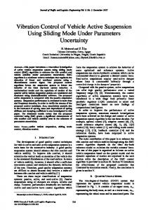
I. INTRODUCTION THE field oriented controlled techniques of a doubly-fed induction machine (DFIG) is an attractive solution for high performance restricted speed-range electric drives and energy generations applications [1], [2]. Figure (1) reports the typical connection scheme of this generator. This solution is suitable for all applications where a limited speed variation around the synchronous speed is present. Since the power handled by the rotor side (slip power) is proportional to slip, an energy conversion is possible using a rotor-side power converter, which handles only a small fraction of the overall system power. Variable-speed energy generation systems have several advantages when compared with fixed-speed synchronous and induction generators [3]. Line Grid
Ps
Qs
DFIG Mechanical Mover Converter AC/AC
ω
i sa , v sa
Control Algorithm
Fig. 1.
Typical connection scheme of a DFIG.
Moreover, if suitable controlled AC/AC converter is used to supply the rotor side, the power components of the overall system can be controlled with low current harmonic distortion in the stator and rotor sides [4], [5]. In order to obtain high performance and better control of the active and reactive powers generated by the DFIG, a sliding mode controller was proposed,
12
Damascus University Journal Vol.
(24)- No. (2) 2008
Dendouga- Abdessemed-
Bendaas- Chaiba
Sliding mode control concept consists of moving state trajectory of the system towards and maintains it around the sliding surface with an appropriate logic commutation, the latter gives birth to a specific behaviour of the state trajectory in a neighbourhood of the sliding surfaces known as sliding regimes [6], [7]. This paper discusses a simulation study of sliding mode controller for active and reactive powers generate by the DFIG II. MATHEMATICAL MODEL OF A DFIG Under the assumption of linear magnetic circuits and balanced operating conditions, the equivalent two-phase model of the symmetrical DFIG, represented in an arbitrary rotating (d-q) reference frame is as follows: dψ sd ⎧ − ω sψ sq ⎪v sd = R s i sd + dt ⎪ dψ sq ⎪ + ω sψ sd ⎪v sq = R s i sq + dt ⎪ dψ rd ⎪ − (ω s - ω )ψ rq ⎪v rd = R r i rd + dt ⎪ ⎨ dψ ⎪v = R i + rq + (ω - ω ) r rq s rd ⎪ rq dt ⎪ 1 ⎪ω& = [Te − Tm ] J ⎪ ⎪ L ⎪T = 3 p m (ψ i − ψ i ) rq sd ⎪⎩ e 2 Lr rd sq
13
(1)
Sliding Mode Control of Active and Reactive Powers Generated by a Doubly-Fed Induction Generator (DFIG)
where
⎧ψ sd ⎪ψ ⎪ sq ⎨ ⎪ψ rd ⎪ψ rq ⎩
= Ls i sd + Lm ird = Ls i sq + Lm irq
(2)
= Lr ird + Lm i sd = Lr irq + Lm i sq
where: isd, isq, ψ rd , ψ rq are the components of the stator current and rotor flux vectors; vrd, vrq are the components of the rotor voltage vector, while vsd, vsq represent the line voltage components (stator windings are directly connected to the line grid), and Rr, Rs, Ls, Lr are stator/rotor resistances and inductances respectively, Lm- mutual inductance; ω - the rotor speed; Te- the external torque applied to the mechanical system of the DFIG; Te- the torque produced by the electrical machine; J the total rotor inertia and ω s the speed of the (d-q) reference frame with respect to the a-axis of the fixed stator reference frame (a-b). x sdq = e x rdq = e
− jθ s
x sab
− j(θ s − θ)
(3)
x ruv
where − jθ e
s = ⎡ cos θ s ⎢⎣− sin θ s
sin θ s ⎤ ⎡0 - 1⎤ ,j= ⎥ ⎢⎣1 0 ⎥⎦ cos θ s ⎦
(4)
where: xyz stands for two dimensional vectors represents the vector of flux, of current and of tension in the generic (y-z) reference frame; subscript ‘s’ stands for stator variables while ‘r’ for rotor variables; (u-v) indicates rotor reference frame and θ is the rotor angle. The main control objective considered is the regulation of DFIM stator-side active and reactive powers, given by [1]:
14
Damascus University Journal Vol.
(24)- No. (2) 2008
Dendouga- Abdessemed-
Bendaas- Chaiba
Ps =
3
Qs =
3
2 2
(v sd i sd + v sq i sq )
(5)
(v sq i sd − v sd i sq )
In order to reduce the effect of the above inaccuracies in the reference frame generation and in vector transformation, a line stator voltage vector reference frame (d-q) has been adopted (the d-axis is aligned with the line voltage vector). This reference frame is independent of machine parameters and position sensor resolution; only information from two voltages sensors and rotor position sensor are needed, instead of four currents sensors. Using the line voltage vector reference frame, a simple and smooth connection of the stator winding to the line grid can be performed during start-up procedure of the DFIG-based system. The synchronous stator voltage oriented reference frame is defined setting in (1) and (3). Under such transformation vsd=U and vsq=0 in DFIM mathematical model (1). In addition, currents isd and isq, in line-voltage oriented reference frame, represent the active and reactive components of the stator current vector. The expression of active and reactive powers (5) can be presented as: Ps =
3
3 Ui sd , Q s = − Ui sq 2 2
(6)
From (6), it follows that active-reactive power control objective is equivalent P
*
Q
*
to active-reactive stator currents control. Let us suppose s and s are the references for the power components at stator side for the DFIM. Using (6), references for the components of the stator current, are given by * * 2 Qs 2 Ps * * , i sq = − i sd = 3 U 3 U
(7)
The control problem of DFIG is formulated in terms of stator activereactive current regulation as to consider the DFIG model (1) under coordinate transformation (3). Let assume that:
15
Sliding Mode Control of Active and Reactive Powers Generated by a Doubly-Fed Induction Generator (DFIG)
• The stator voltage amplitude and frequency are constants (stator windings are directly connected to infinite electrical network). • References for active and reactive stator currents are constant and bounded, or represent ramp signals with bounded first derivate and bounded amplitude. • Under the assumption of a properly controlled primary mover the rotor speed is time varying, measurable and bounded together with its first order time-derivate. • Stator currents and voltages as well as rotor position and speed are obtained by estimation. III. DESIGN OF SLIDING MODE CONTROL ALGORITHM The method consists to calculate the equivalent and discontinuous components of control variable from an adequate surface of sliding mode chosen [6]. In this case we chose the error as being the sliding surface * S(ψ rd ) = ψ rd − ψ rd ; * S(ψ rq ) = ψ rq − ψ rq .
(8)
The first order derivate of (8), gives: * & rd ; S& (ψ rd ) = ψ& rd − ψ * & rq . S& (ψ rq ) = ψ& rq − ψ
* ψ rd
* ψ rq
(9)
where flux references, and , will be defined later according to stator current control objectives. In the sliding mode regime the dynamic of the system in sliding mode is subjected to the following conditions S(ψ) = 0 thus for the ideal sliding & mode we have also S(ψ ) = 0 .
16
Damascus University Journal Vol.
(24)- No. (2) 2008
Dendouga- Abdessemed-
Bendaas- Chaiba
Substituting rotor flux by their expressions obtained after arrangement of the model (1) into equations (9), and with the conditions of the sliding mode, the components of the reference stator voltage are given by: 1 * 1 * * * L m i sd ; v rdeq = ψ rd + ψ rd − ωr ψ rq − Tr Tr
(10)
1 * 1 * & *rq + ωr ψ*rd + v rqeq = ψ L mi sq . ψ rq − Tr Tr
Where v rdeq and v rqeq are the equivalent components of the rotor voltage respectively. Similarly to (8), the sliding surface of the stator currents is defined by: * S(i sd ) = i sd − i sd ; * S(i sq ) = i sq − i sq .
(11)
After the derivation of (11), the rotor flux of reference is given in sliding mode regime by: σL r * ψ rd = ωs L m
⎛ Rs * ⎞ R 1 ⎜⎜ i sd − ωs i *sq − U − s &i *sq ⎟⎟ σ σ σω s ⎝ ⎠
⎛ Rs * ⎞ R * ⎜⎜ − i sq − ωs i *sd − s &i *sd ⎟⎟ ψ rq = ωs L m ⎝ σ σωs ⎠ σL r
where
σ = L s (1 −
2 Lm ) L r Ls
is the total leaking constant.
The rotor voltages of references are defined by: * v rd = v rdeq + v rdn * v rq = v rqeq + v rqn
17
(13)
(12)
Sliding Mode Control of Active and Reactive Powers Generated by a Doubly-Fed Induction Generator (DFIG)
Where ‘eq’ and ‘n’ indicate the equivalent and discontinuous components of the rotor voltage reference respectively. The nonlinear component is added to the global function of the controller in order to guarantee the attractiveness of the chosen sliding surface [7]. This latter is achieved by the condition S( x )S& ( x ) < 0 [6,7]. A simple form of the control action using sliding mode theory is a relay function, which is given by equation (14). (14) U n = K sgn(S( x )) However, this latter produces a drawback in the performances of a control system, which is known as chattering phenomenon. In order to reduce the chattering phenomenon due to the discontinuous nature of the controller, a smooth function is defined in some neighbourhood of the sliding surface with a threshold as seen in Fig.2, [6]
Un
+k -ε
+ε
S(x)
-k Fig. 2. Smoothed sign function.
18
Damascus University Journal Vol.
(24)- No. (2) 2008
Dendouga- Abdessemed-
Bendaas- Chaiba
IV. DIAGRAM OF THE CONTROL STRATEGY
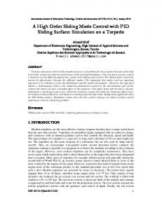
Fig. 3. Configuration of the power control of the DFIG
In this section the diagram of the control strategy using the sliding mode control of the active and reactive powers by the stator current such as the active power is controlled by the direct current and the reactive power by the quadratic current is presented in the figure (3). The nominal parameters of the DFIG are reported in table 1.
19
Sliding Mode Control of Active and Reactive Powers Generated by a Doubly-Fed Induction Generator (DFIG) Parameters Power Voltage Frequency Pole pairs Speed Torque Stator resistance Rotor resistance Stator inductance Rotor inductance Mutual inductance
values 5 kW 380V (Y) 50 Hz 3 100 rad/s 50 N.m 0.95 Ω 1.8 Ω 0.094 H 0.088 H 0.082 H
TABLE I: DFIG PARAMETERS
In order to provide independent control using sliding mode controllers of the stator active power Ps and reactive power Qs of the DFIG by means of the stator current regulation, a model of the DFIG is defined in the stator-flux oriented reference frame. The aim is to represent Ps and Qs as functions of the individual stator current components. Subsequently, the desired * * Ps and Q s can determine the reference stator currents, which allow the
calculation of the rotor voltage reference components in which they are used for PWM generation command signal of inverter, which is used to feed the rotor circuit. To guarantee a drive of the DFIG around its speed of synchronism, is used a speed regulator.
V. SIMULATION RESULTANTS The sliding mode controllers based on the stator-flux orientation reference is realized in Matlab/Simulink in order to control the active and reactive powers
20
Damascus University Journal Vol.
(24)- No. (2) 2008
Dendouga- Abdessemed-
Bendaas- Chaiba
by the direct and quadratic components of the stator currents via a desired powers flow between the network and the generator. The active-reactive stator current and its reference are provided in figures 4 and 5. These figures represent a good pursuit, except that the presence of the oscillations during the transient mode according a star up of mechanical mover. A very good decoupling between the direct and quadratic components of the stator currents is obtained, ensuring a decoupling between the active and reactive powers (Fig.6); this leads to a good control of the power flow between the grid and the machine at all time. The speed and torque of the DFIG are depicted in figure 7. According to the latter, it is seen that motoring speed stays constant due a regulator speed in addition the torque depends directly on the direct component of the stator current. The rotor phase voltage obtained on the output side of PWM inverter is represented by figure 8. The use of an inverter with PWM with a high switching frequency (5 kHz) makes it possible to improve the sinusoidal waveform of the stator current, as illustrated by the zoom of the figure 9 in the figure 10.
21
Sliding Mode Control of Active and Reactive Powers Generated by a Doubly-Fed Induction Generator (DFIG)
22
Damascus University Journal Vol.
(24)- No. (2) 2008
Dendouga- Abdessemed-
Bendaas- Chaiba
VI. CONCLUSION The sliding mode control based of the stator-flux orientation of the power flow of the DFIG by the stator current provides global asymptotic regulation ( S ( x) S& ( x) p 0 ) in presence of the stator current reference variation. The simulation tests confirm high dynamic performance and robustness of the proposed controller. The proposed controller is suitable for energy generation applications, where restricted variations of the speed around the synchronous velocity are present. The use of the PWM technique inverter-driven the rotor of DFIG enables, to obtain perfectly sinusoidal currents on the stator side, therefore the energy provided by the machine to the network is a clean energy without harmonics.
23
Sliding Mode Control of Active and Reactive Powers Generated by a Doubly-Fed Induction Generator (DFIG)
References [1] W. Leonhard, Control of electrical drives, Springer-Verlag, 2ème Edition, 1996. [2] A.L. Nemmour, ″Contribution à la commande vectorielle de la machine asynchrone à double alimentation″, Thèse de Magister, Université de Batna, 2002. [3] A. Petersson, ″Analyse, Modeling and control of doubly-fed induction generators for wind turbines″, thèse de licence en électrotechnique, université technologique de Chalamer, Göteborg, Sweden 2003. [4] L. Zhang et C. Watthanasarn, ″A matrix converter excited doubly-fed induction machine as a wind power generator″, IEE Conf, No.456, Sep 1998, pp.532-537. [5] R. Pena, J.C. Clare and G.M. Asher, ″Doubly fed induction generator using back-to-back PWM converters ands its application to variable-speed wind-energy generation″, IEE Proc, Vol.143,No.3, May 1996, pp.231-241. [6] M.O. Mahmoudi, N. Madani, M.F. Benkhoris ″Cascade sliding mode control of a field oriented induction machine drive″, Eur. Phys, AP 7, 1999, pp.217-225. [7] V.I Utkin, ″Sliding mode control design principles and applications to electric drives″, IEEE Trans, on Industrial Electronics, Vol.40, No.1, February 1993, pp.23-36.
Received, 20 March, 2007.
24