Oct 19, 2011 - not include any effects from either edge focusing or sextu- poles .... edge focusing is present; and (iv) the energy spread is ...... A 482, 65 (2002).
PHYSICAL REVIEW SPECIAL TOPICS - ACCELERATORS AND BEAMS 14, 104202 (2011)
Smooth approximation model of dispersion with strong space charge for continuous beams S. Bernal, B. Beaudoin, T. Koeth, and P. G. O’Shea* Institute For Research in Electronics and Applied Physics, University of Maryland, College Park, Maryland 20742, USA (Received 28 March 2011; published 19 October 2011) We apply the Venturini-Reiser (V-R) envelope-dispersion equations [M. Venturini and M. Reiser, Phys. Rev. Lett. 81, 96 (1998)] to a continuous beam in a uniform focusing/bending lattice to study the combined effects of linear dispersion and space charge. Within this simple model we investigate the scaling of average dispersion and the effects on beam dimensions and show that the V-R equations lead to the correct zero-current limits. We also introduce a generalization of the space charge intensity parameter and apply it to the University of Maryland Electron Ring and other machines. In addition, we present results of calculations to test the smooth approximation by solving the V-R original equations and also through simulations with the matrix code ELEGANT. DOI: 10.1103/PhysRevSTAB.14.104202
PACS numbers: 29.27.Bd, 41.85.Ja
I. INTRODUCTION Control of the maximum beam size and halo in high energy proton and ion accelerators is paramount to avoid machine activation and beam degradation from magnet nonlinearities, image forces, and other effects. One aspect of this control concerns the effects of dispersion and space charge. The scope of the paper is to present scaling laws that permit the simple evaluation of average dispersion and beam dimensions in the presence of strong space charge. At least two theories exist that address the effect of space charge on the dispersion function for coasting, continuous (unbunched) beams in accelerators. The theories were developed in 1998 by Venturini and Reiser [1], and, independently, by Lee and Okamoto [2]. Other authors have used one or the other approach to model proton storage rings at KEK [3–5] and SNS [6], but no experimental tests of either theory have been carried out. A major component of the Venturini-Reiser (V-R) theory is the realization that the standard four-dimensional rms emittance in the lab frame of reference is not conserved in the presence of dispersion, with or without space charge. Although the emittance growth from dispersion alone is ordinarily very small compared to the one from, e.g., standard envelope mismatch, the nonconservation of rms emittance from dispersion can be used to derive a theory of dispersion in the presence of space charge. In the LeeOkamoto (L-O) theory, on the other hand, conservation of emittance is not addressed, but the theory in the original paper is applied to crystalline beams where emittance is negligible. In both theories, a set of envelope-dispersion *Also at Department of Electrical and Computer Engineering, University of Maryland. Published by the American Physical Society under the terms of the Creative Commons Attribution 3.0 License. Further distribution of this work must maintain attribution to the author(s) and the published article’s title, journal citation, and DOI.
1098-4402=11=14(10)=104202(15)
equations are derived that constitute a generalization of the Kapchinsky-Vladimirsky (K-V) envelope equations for linear space charge without dispersion [7,8]. Early work on dispersion, space charge, and emittance growth was carried out by Barnard et al. [9], who followed a different approach from V-R and L-O to derive a set of first-order differential equations for the first and second moments of the beam distribution; the authors also addressed an equilibrium beam situation equivalent to a smooth approximation of the theory. The work was shown later to be equivalent to the V-R theory [10]. We will discuss this early work further below and compare some of its results with our own. Although it can be argued that the local values of the beam envelope and/or the dispersion function (which can be readily obtained by numerical solutions of the equations in the V-R or L-O theories) are more important in practice than the average values, knowledge of the latter can provide useful insights for scaling and initial design studies. An example is the smooth or uniform-focusing approximation of the standard K-V envelope equations without dispersion. The theory is presented in [7] and further explored in a number of publications on both theoretical and experimental aspects [11–13]. The envelope-dispersion equations can also be employed for beam stability studies by using the standard method of small oscillations around matched envelope and dispersion functions to derive dispersion relations (the word ‘‘dispersion’’ used in a different sense in that context) as it is done for the case without dispersion [7]. A study along those lines by Ikegami et al. [4] has shown the existence of dispersion modes besides the known breathing and quadrupole modes of the K-V distribution. In this paper, we will derive explicitly the smooth focusing-bending approximation of the V-R theory to estimate the average beam radius and average dispersion in an alternating-gradient focusing lattice. The average dispersion will be of interest for comparison with actual
104202-1
Published by the American Physical Society
S. BERNAL et al.
Phys. Rev. ST Accel. Beams 14, 104202 (2011)
solutions of the V-R equations as well as with calculations with the code ELEGANT. We should also note that the smooth focusing-bending approximation has been applied by both Venturini [14] and Barnard [10] to study the effects of the transition from a straight channel into a dispersive lattice. Both treatments of the problem assume stationary K-V beams in both the straight and dispersive regions and calculate the effects on emittance and beam size. By contrast, we consider in this paper only a dispersive lattice with near-matched conditions of the envelope and dispersion functions and assume that the standard rms emittance is conserved. Another related important consideration is the type of lattice for which the theory presented here is applicable: the V-R equations and their algebraic form do not include any effects from either edge focusing or sextupoles; furthermore, a reasonably ‘‘smooth’’ physical lattice is assumed. A lattice with a racetrack geometry with long straight sections (as in energy recovery linacs), for example, may not lend itself for an accurate treatment of beam envelope and dispersion functions with the approach adopted here. Finally, we introduce a single parameter that makes possible to characterize the effects of both space charge and dispersion in an average sense; this parameter can be considered as a generalization of one introduced to characterize (incoherent) space charge alone [7]. A combination of parameters appears naturally in the simplest treatment of dispersion with or without space charge. If both the betatron amplitude and dispersion functions are matched, these parameters are (see next section) the ratio of lattice average dispersion to average zero-current beam radius (D0 =a0 ), the rms fractional momentum error or spread (�), and the ratio of average ‘‘depressed’’ dispersion to average depressed beam radius (D=a). The word depressed, which does not imply ‘‘reduced,’’ is used here liberally to indicate the effects of linear space charge. Furthermore, we depart from the standard notation for dispersion (�) and use ‘‘D’’ instead, and reserve ‘‘�’’ to denote space charge tune depression. As shown below, the product 2D�=a defines a dimensionless parameter that we denote by �, or �0 in the absence of space charge. The ratio �0 =� turns out to be a possible measure of the combined effects of dispersion and space charge, with �0 =� ’ 1:0 indicating small effects from either, �0 =� * 1:0 strong dispersion but small space charge and �0 =� & 1:0 strong space charge and dispersion. In circular machines of interest, like storage rings for spallation neutron sources (see e.g. [15]), D0 =a0 ¼ 15–30, while � ’ 10�2 , so �0 ’ 0:3–0:6. In this case, although the effects of dispersion and space charge on the average beam radius are not entirely negligible, we obtain �0 =� ’ 1:0. By contrast, a typical ring envisioned for a heavy-ion fusion driver [16], having also D0 =a0 ¼ 15–30, will have much stronger effects from both space charge and dispersion unless the fractional momentum error is kept significantly
smaller (� ’ 10�4 ). Even in this latter case we obtain �0 =� ’ 0:86 [17]. By contrast with high power proton storage rings or heavy-ion fusion drivers, electron circular machines like storage rings for third generation light sources do not display any space charge effects but dispersion can be significant. For the storage ring of the Advanced Light Source at Berkeley Lab [18], for example, we have D0 =a0 ’ 900, on account of a small beam dimension in the horizontal plane, a0 , of the order of 200 �m. Therefore, with � ¼ 6:5 � 10�4 , we get �0 ¼ 1:1 and �0 =� ¼ 1:5. Interestingly, with very low-energy, high-current electrons, and a dense strong focusing lattice as in the University of Maryland Electron Ring [19], it is possible to have a number of beams with a diverse combination of space charge, dispersion, and emittance effects on the average beam radius. In fact, using � ¼ 0:01 and currents of 0.6, 6.0, and 21, and 104 mA at 10 keV, we obtain �0 =� ¼ 1:0, 0.65, 0.44, 0.27 with D0 =a0 ¼ 30, 16, 15, 10.5, respectively, at a typical operating point. Naturally, these calculations reflect an ideal situation as qualified in Sec. V. The paper is organized in six sections. Section II presents a review of basic relations for the beam centroid and rms beam radius in the presence of linear dispersion, including the corresponding relations with space charge. In Sec. III, the envelope-dispersion equations of the V-R theory are presented and cast in a form amenable for analysis within the uniform-focusing/bending approximation discussed in Sec. IV. In the latter part of Sec. IV, we apply the smooth approximation equations to a number of beams in the University of Maryland Electron Ring (UMER). In Sec. V we compare the results of the smooth approximation with average quantities obtained from direct solutions of the V-R equations as well as from calculations with the matrix code ELEGANT. Section VI is devoted to summary and conclusions; details of the implementation of incoherent space charge in ELEGANT are deferred to the Appendix. II. BASIC RELATIONS We review in this section the relations for orbit displacement and beam size that are valid when space charge effects are negligible; then, we extend the relations to include space charge effects. The main assumptions are: (i) the beam is continuous; (ii) dispersion is linear; (iii) no edge focusing is present; and (iv) the energy spread is uncorrelated along and across the beam. In the absence of space charge, the horizontal displacement of a particle from the reference trajectory is given by x ¼ x� þ D0 �;
(1)
where x� is the betatron oscillation amplitude, � � �p=p0 is the fractional momentum error, and D0 is the standard dispersion without space charge. The fractional momentum error � is assumed to be uncorrelated with both x and s
104202-2
SMOOTH APPROXIMATION MODEL OF DISPERSION WITH . . . Phys. Rev. ST Accel. Beams 14, 104202 (2011) (distance along beam line). For rings, x� in Eq. (1) is replaced by xco þ x� where xco is the closed orbit displacement; but the closed orbit is ordinarily set as the reference orbit so xco ¼ 0. With space charge, we write xsc ¼ xsc� þ D�:
(2)
Clearly, in a circular machine D still represents the closed orbit of off-momentum particles with space charge forces simply enhancing the displacements; thus, we expect D > D0 . Without image forces and in the absence of closed orbit errors and assuming a symmetrical phase-space distribution, we have hx� i ¼ 0 ¼ hxsc� i for the 4D phase-space averages at a given s plane. An equivalent statement, under these assumptions, is that incoherent space charge does not change the reference trajectory. Therefore, we obtain hxsc i � hxi ¼ ðD � D0 Þh�i:
(3)
Equation (3) is the same as Eq. (10) in a paper by Ohkawa and Ikegami on dispersion matching from a linac into a ring at KEK [3]. It would seem that Eq. (3) allows us to measure dispersion with space charge by measuring orbits for low- and high-current beams under the same conditions of bending/steering. However, it is reasonable to assume that the distribution of momentum errors is centered at zero in both cases, so no change in orbits can be observed. Since by definition hx� �i ¼ 0 ¼ hxsc� �i, additional equations for the dispersion and its derivative follow immediately from Eq. (1) or Eq. (2), after multiplying by � and taking averages: D¼
hx�i �16 ; ¼ h�2 i �66
D0 ¼
hx0 �i �26 ; ¼ �66 h�2 i
(4)
where the last equalities are written in terms of the beam sigma matrix [3]. Equations (4) are valid with or without (linear) space charge and are useful for computational purposes; however, calculations with � ! 0 must be approached with caution (see Sec. V). To measure the effects of incoherent space charge on dispersion we need to evaluate the second moments of the beam distribution (and energy spread). Without space charge, the rms value of x is hðx � hxiÞ2 i1=2 ¼ ½hx2� i þ D20 h�2 i�1=2 :
(5)
With space charge we have hðxsc � hxsc iÞ2 i1=2 ¼ ½hx2sc� i þ D2 h�2 i�1=2 :
(6)
We have used hx� �i ¼ 0 ¼ hxsc� �i, and h�i ¼ 0. Further, by using a0 ¼ 2hx2� i1=2 , we rewrite Eq. (5) in the form 2xrms ¼ ½a20 þ 4D20 h�2 i�1=2 ¼ a0 ð1 þ �20 Þ1=2 ;
(7)
where �0 � 2D0 �=a0 , with � � h�2 i1=2 denoting the rms fractional momentum error or spread. It is clear that the
linear approximation used in Eqs. (1) and (2) implies that �20 � 1. In an attempt to include space charge, we could write, with a � 2ðxrms Þsc , a ¼ ½a2sc þ 4D2 h�2 i�1=2 ;
(8)
which turns out to be approximately correct for small � and with proper expressions for asc and D (Sec. IV). In general, however, it is not possible to separate the effects of space charge and dispersion in the way implied by Eq. (8): as the beam enlarges in the horizontal plane from dispersion effects, the space charge force on a given particle also changes. The correct general expression that replaces Eq. (7) when linear space charge and linear dispersion are combined will be derived in the next section. As a final note, the use of 2xrms in Eqs. (7) and (8) for the effective beam radius assumes than an equivalent K-V beam distribution can be employed for arbitrary beam current and nonzero dispersion. This is a good approximation, as discussed in [14]. III. EMITTANCE AND THE V-R ENVELOPE-DISPERSION EQUATIONS We apply the envelope-dispersion equations of the V-R theory to a matched beam in a uniform-focusing/bending channel. For simplicity, we assume an accelerator where bending occurs only on the horizontal plane and without horizontal edge focusing (i.e. bending occurs by means of rectangular dipole magnets). Further, we assume that the beam has an uncorrelated rms energy spread that is small (�1%–2% of the nominal beam energy), but that no limits are imposed on the effects of transverse space charge. Thus, the theory is self-consistent only in regard to transverse space charge and dispersion; a self-consistent treatment in 6D, whereby the energy spread itself is affected by longitudinal space charge, would require a more elaborate theory. Finally, it will be implicit that an equivalent K-V beam can be used to describe the beam distribution in the presence of both linear space charge and linear dispersion. Incoherent space charge forces defocus the beam in both horizontal and vertical planes, but horizontal dispersion acts mostly on the horizontal plane, causing enlargement of the beam in that plane; in an alternating-gradient lattice, however, coupling introduces effects of horizontal dispersion on the vertical plane too but the effect is not as significant. Because of the reduced effective focusing caused by space charge, for a given momentum error the main effect is an increase in dispersion. The reference orbit, however, is not affected by incoherent space charge, as it is given by the motion of the beam’s centroid. By contrast, image forces would affect the reference orbit for an off-center beam. Both the V-R and L-O theories rely on a canonical transformation of variables to a system on the off-momentum particle orbit. In this system, the emittance is conserved but
104202-3
S. BERNAL et al.
Phys. Rev. ST Accel. Beams 14, 104202 (2011)
is different from the standard emittance. Since bending occurs only on the horizontal plane, only the standard horizontal rms emittance, "2x rms ¼ hx2 ihx02 i � hxx0 i2 ;
(9)
is not conserved in the V-R theory. Instead, the new emittance that is conserved is written as [20] �2dx
¼
�2x rms
�
�2 h½x0 D
�
xD0 �2 i;
envelope oscillations, so rms envelope and dispersion matching must be treated simultaneously for optimal beam transport.
(10)
where D � DðsÞ is the horizontal dispersion, � � pffiffiffiffiffiffiffiffiffiffiffiffiffiffiffiffiffiffiffiffiffiffiffi hð�p=p0 Þ2 i is the rms fractional momentum error or spread, and prime indicates derivatives with respect to ‘‘s,’’ the distance along the reference trajectory. Angular brackets represent phase-space averages. In the same V-R theory, the following envelope-dispersion equations are derived [21]: � � 2K 1 D00 þ k2x0 � D � ¼ 0; (11a) XðX þ YÞ � 2K �2 þ ½XX 0 � DD0 �2 �2 X00 þ k2x0 X � � dx 3 2 2 XþY X ð1 � 4�X2D Þ � � X 02 4�2 D þ D02 ¼ 0; � þ (11b) X X � �2y 2K � 3 ¼ 0; (11c) Y 00 þ k2y0 X � XþY Y where � is the local bending radius at the nominal energy, kx0;y0 are wave numbers representing external focusing, X, Y are the 2rms beam semiaxes dimensions, K is the generalized beam perveance [7], and �x;y are the effective (i.e. unnormalized, 4rms) standard emittances. All quantities except K are functions of s. It should be noted that these envelope-dispersion equations were rederived by Okamoto and Machida in a 2002 paper on dispersion and resonances [5]. Some general observations can be made about Eqs. (11a)– (11c) before we undertake their solution. First, Eq. (11a) for the dispersion, which dates back to Al Garren’s work for heavy-ion fusion [22], displays a ‘‘defocusing’’ effect from space charge like the one present for the envelopes in Eqs. (11b) and (11c). Thus, the matched dispersion undergoes fast oscillations with the frequency of the lattice (0.32 m in UMER) and slow oscillations with wave number qffiffiffiffiffiffiffiffiffiffiffiffiffiffiffiffiffiffiffiffiffiffiffiffiffiffiffiffiffiffiffiffiffiffiffiffiffiffiffiffiffiffi k2x0 � 2K=XðX þ YÞ. Second, the denominator of the emittance term in Eq. (11b) contains the factor ð1 � 4�2 D2 =X 2 Þ, which implies that 2�D=X < 1 since the emittance contribution cannot be infinite or change sign [this is also evident from Eq. (8) with the substitutions a ¼ X, and h�2 i ¼ �2 ]. This latter condition is equivalent to saying that the displacement, �D, from the reference trajectory, cannot be equal or exceed half the envelope effective radius. Third, the oscillations of the (horizontal) dispersion function are coupled to those of the (mostly horizontal)
IV. UNIFORM FOCUSING-BENDING APPROXIMATION Using the V-R theory [1] and assuming that the standard 4rms emittances �x;y are conserved (see Sec. V), the envelope-dispersion equations in the smooth approximation are (see also [4]) � � 2K 1 D � ¼ 0; (12a) k2x0 � aða þ bÞ � 2K 4�2 D �2x � � 3 k2x0 a � ¼ 0; (12b) ða þ bÞ a � a ð1 � 4�22D2 Þ a
�2y 2K � 3 ¼ 0; k2y0 b � ða þ bÞ b
(12c)
where D now defines the average horizontal dispersion, � is the average machine radius, kx0;y0 represent external focusing (constants in the smooth approximation), and a, b define the constant average or stationary semiaxes beam dimensions. If we define �x� , and �y� by the following relations, sffiffiffiffiffiffiffiffiffiffiffiffiffiffiffiffiffiffiffiffiffiffiffiffiffiffiffiffiffiffiffiffi sffiffiffiffiffiffiffiffiffiffiffiffiffiffiffiffiffiffiffiffiffiffiffiffiffiffiffiffiffiffiffiffi 2K 2K �x� � 1 � ; (13) ; �y� � 1 � 2 aða þ bÞkx0 bða þ bÞk2y0 we can rewrite Eqs. (12a)–(12c) in a more compact form: �2x� k2x0 D � �2x� k2x0 a �
1 ¼ 0; �
or D ¼
D0 ; �2x�
(14a)
4�2 D �2x � 3 ¼ 0; a � a ð1 � 4�22D2 Þ a
(14b)
�2y� k2y0 b �
(14c)
�2y ¼ 0: b3
It is possible to write an (implicit) expression for a2 from Eqs. (12a)–(12c) or (14a)–(14c). Multiplying out Eq. (14b) by ð1 � 4�2 D2 =a2 Þ and dividing by �2x� k2x0 , we obtain a homogeneous quartic equation in a. By solving the equation for a2 and using Eq. (14a), we obtain a20 þ 4�2 D2 ða; b; �Þ; (15) �x� ða; b; �Þ pffiffiffiffiffiffiffiffiffiffiffiffi where a0 � �x =k0 , and the dependence of �x� and D on a, b, and � is indicated explicitly. Equation (15) is of the form of Eq. (8). In the limit of small momentum error but arbitrary space charge, the quantities defined in Eq. (13) reduce to the standard space charge tune depressions that we denote by �x0 , and �y0 . In this limit, the first term in Eq. (15) is a20 =�x0 , which is the correct expression for the effective beam radius (squared) with space charge but no dispersion.
104202-4
a2 ¼
SMOOTH APPROXIMATION MODEL OF DISPERSION WITH . . . Phys. Rev. ST Accel. Beams 14, 104202 (2011) The three second-order equations of the V-R theory, Eqs. (11a)–(11c), are equivalent to six first-order equations derived by Barnard et al. [9,10], if the generalized emittance [Eq. (10)] is conserved. Furthermore, Eq. (10) of Ref. [9], �y2 ffi �x2 � k2�0 =�x2m k4 , can be shown to be equivalent to our Eq. (15) [23]. Interestingly, the approach taken by Barnard et al. of assuming transverse energy equipartioning leads to results very similar to those presented here. It does not appear feasible to obtain a general explicit expression for the effective beam radius ‘‘a’’ from Eq. (15) because of the appearance of ‘‘a’’ on both sides of the equation. However, an approximation can be easily derived if a ffi b, �x ¼ �y , kx0 ¼ ky0 � k0 , and we ignore the term ð1 � 4�2 D2 =a2 Þ in the denominator of the emittance term in Eq. (12b) or Eq. (14b). This latter step is justified for space charge dominated transport whereby the emittance term in the envelope-dispersion equations (including the ignored factor) is small compared to the space charge term. The result, from Eq. (12b) using a simplified emittance term, is sffiffiffiffiffiffiffiffiffiffiffiffiffiffiffiffiffiffiffiffiffiffiffiffiffiffiffiffiffiffiffiffiffiffiffiffiffiffiffiffiffiffiffiffiffiffiffiffiffiffi � �2 K K 2 2 2 a ffi 2 þ 2� DD0 þ þ 2� DD þ a40 ; (16) 0 2k0 2k20 where a0 was defined above. The last equation can be rewritten in terms of the parameter u � K=2�x k0 introduced in Ref. [7]: sffiffiffiffiffiffiffiffiffiffiffiffiffiffiffiffiffiffiffiffiffiffiffiffiffiffiffiffiffiffiffiffiffiffiffiffiffiffiffiffiffiffiffi ffi � � 2�2 DD0 2�2 DD0 2 a2 ffiuþ þ uþ þ 1: (17) a20 a20 a20 pffiffiffiffiffiffiffiffiffiffiffiffiffiffi If � ¼ 0, we get a2 =a20 ffi ðu þ u2 þ 1Þ, which is the correct uniform focusing approximation, zero-momentum error limit [7]. In the zero-current limit, though, we obtain a2 =a20 ! 1 þ 2�2 D20 =a20 , which is not the correct limit as can be seen by comparing this expression with Eq. (7). To obtain the correct limit, ð1 � 4�2 D2 =a2 Þ must be included in the emittance term in Eq. (12b), as can be realized from Eq. (15), which is exact within the uniform focusing/ dispersion approximation. To make Eq. (16) or Eq. (17) useful for scaling studies, we use the following additional expressions: � � D0 D0 1 1 � �2x0 D¼ 2 ffi 2 ; u¼ ; (18) 2 �x0 �x� �x0 where we have assumed small momentum error in the approximation �x� ’ �x0 on the left [see Eqs. (13) and (14a)]. Thus, we obtain, finally, sffiffiffiffiffiffiffiffiffiffiffiffiffiffiffiffiffiffiffiffiffiffiffiffiffiffiffiffiffiffiffiffiffiffiffiffiffiffiffiffiffiffiffiffiffi � � 1 � �2 �20 1 � �2 �20 2 a2 þ 2þ þ 2 þ 1; (19) ffi 2� 2� a20 2� 2� where we have omitted the subscript ‘‘x0’’ to simplify the notation.
Equation (19) is the main result. The equation is not exact in any particular limit of nonzero space charge and/or dispersion. We reiterate the conditions for the validity of Eq. (19): a ffi b, �x ¼ �y , kx0 ¼ ky0 � k0 , 4�2 D2 =a2 � 1, and small momentum error. The latter two conditions can be combined to obtain �2 D20 �
a20 �3 ; 4
(20)
where we have used D ffi D0 =�2 , and a2 ffi a20 =�, since most of the increase in beam size comes from space charge if � is small. The condition in Eq. (20) is somewhat too restrictive as D is overestimated by the approximation used. However, we can still use the relation to find upper limits to the momentum error �; we consider two cases of D0 =a0 (10 and 30) and two cases of � (0.1 and 0.3): we find maximum � of 0.2% and 0.8% for ðD0 =a0 ; �Þ ¼ ð10; 0:1Þ and (10, 0.3), respectively, and 0.05%, 0.3% for ðD0 =a0 ; �Þ ¼ ð30; 0:1Þ and (30, 0.3). Thus, Eq. (19) is valid over a broad range of values of average lattice dispersion and beam currents with more severe restrictions on the momentum error at extreme conditions of space charge (� of the order of 0.1). For values of � � 1%, on the other hand, Eq. (19) can only provide a rough or fair estimate of beam radius in most cases. For completeness, we examine also the condition a ffi b behind Eq. (19). By subtracting Eq. (12c) from Eq. (12b) and neglecting the emittance terms, i.e., assuming space charge dominated beam transport, we can obtain the degree of anisotropy caused by dispersion and space charge when the momentum error is small: 4�2 D2 �2 a�b ffi 2 0 ¼ 0: � a0 � a
(21)
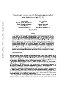
For D0 =a0 ¼ 10, � ¼ 0:1, for example, we find ða � bÞ=a ffi 4 � 103 �2 , or a 1% anisotropy at � ¼ 0:16%. For beam transport in UMER, Eq. (19) overestimates the effect on beam radius when both space charge and momentum error are significant (� & 0:3, � * 1%) because D is not as large as implied by the first approximation in Eq. (18); the equation also underestimates the effect for small current because the contribution from the emittance term [Eq. (14b)] is given less weight by ignoring the factor ð1 � 4�2 D2 =a2 Þ�1 . However, the results are accurate within 10% or better [of the exact result from Eqs. (12a)– (12c)] as shown in Fig. 1 [24]. Figure 1 illustrates the results of calculations using Eq. (19) of normalized beam radius a=a0 as a function of standard tune depression � for four values of �0 ¼ 2�D0 =a0 : 0.0 (no momentum error), 0.20, 0.30, and 0.60. Also shown are the results of exact calculations, within the smooth approximation [Eqs. (14a)–(14c)], for five beams in UMER (� ¼ 0:01 for all cases but one), the SNS proton storage ring [15] and a hypothetical heavy-ion fusion ring [16]. We assume also � ¼ 0:01 for these latter cases. The
104202-5
S. BERNAL et al.
Phys. Rev. ST Accel. Beams 14, 104202 (2011)
FIG. 1. Approximate normalized horizontal beam semiaxis as a function of standard tune depression [see Eq. (19)] for four values of the parameter �0 ¼ 2D0 �=a0 , with � ¼ 0:0 for the first case (red dashed line) and � ¼ 0:01 for the other three cases; all cases include full space charge. Five cases of beams in UMER are also indicated [exact calculations from Eqs. (14a)–(14c)] by their currents; the operating point in UMER is 0 ¼ 6:37, and the edge emittances are given in Table I. Also shown are points for the proton ring at SNS and a hypothetical ring for heavy-ion fusion (HIF).
first two columns in Table I contain the main beam parameters in UMER; we also include calculations of beam dimensions, normalized to the space charge value without dispersion aS , for � ¼ 0:002 and � ¼ 0:01. We justify below the choice of these momentum errors for a 10 keV electron beam in UMER. We emphasize that there are two major, not entirely independent, assumptions behind all approximations above: first, both rms envelope and dispersion matching are satisfied (or the mismatch is small), and, second, the rms emittance change is negligible. Clearly, these assumptions
may not be realistic for large momentum errors (>1%), for which case the smooth focusing/bending approximation may not be accurate, but those cases are considered extreme. Furthermore, Eqs. (19)–(21) and Fig. 1 may give the impression that �0 and � (standard horizontal tune depression) can be specified independently for a given beam current and emittance. This is not the case as � is a function of a0 ¼ ð�=k0 Þ1=2 . To specify the beam transport problem completely in the smooth approximation and in the presence of both space charge and dispersion, we need the beam current, energy, rms emittance, and rms fractional momentum error � (beam parameters) as well as the average machine radius and magnet strength (lattice parameters). The standard tune depression and the ratio D0 =a0 , in turn, are independent of �, but �0 is proportional to �. To illustrate this further, we have included in Fig. 1 a point labeled ‘‘6 mA*’’ on the curve for �0 ¼ 0:60; this point is possible if we adjust both the emittance and the momentum error (� ¼ 0:015) to yield �0 ¼ 0:60 and � ¼ 0:50 while keeping other parameters the same as for the standard transport of 6 mA in UMER (see Table I). We can now define a dispersion-space charge intensity parameter, D : � �� ��1 �0 D0 D ¼ D � : � a0 a
The ratio D0 =a0 is fairly constant (10–30) over a broad range of beam parameters ffi machines, since D0 , a0 are pffiffiffiffiffiffiffiand both proportional to �x0 [25,26]. Furthermore, from Eq. (22) we see that D ¼ 1 with no space charge and no dispersion; D ’ a=a0 , with no space charge (* 1:0 with strong dispersion); D & 1:0, with strong space charge. In this latter case, we can use the approximations D ffi D0 =�2 and a ffi a0 =�1=2 , valid for small �, to obtain D ffi �3=2 . For larger �, of the order of 1%, and strong space charge, D is still significantly larger than D0 , although not as large
TABLE I. Basic parameters of UMER beams at 10 keV and results of smooth approximation calculations of beam horizontal (a) and vertical (b) semiaxes dimensions (normalized to the space charge, zero-dispersion value aS ), from Eqs. (14a)–(14c). The operating point is x0 ¼
y0 ¼ 6:37, so the zero-current average horizontal dispersion is D0 ¼ 0:045 m, and the zerocurrent average beam radii are a0 ðmmÞ ¼ 0:54 � �0:5 ð�mÞ. The emittances are 4 � rms, unnormalized. Current (mA), emittance (�m) 0.0, 8.05 0.6, 8.05 6.0, 26.2 6.0a, 17.2 21, 30.2 104, 64.4
Standard tune depression 1.00 0.85 0.62 0.50 0.30 0.14
(22)
a=aS , b=aS � ¼ 0:2% � ¼ 1% 1.01, 1.00 1.01, 1.00 1.01, 1.00 1.01a, 1.00a 1.01, 1.00 1.01, 1.00
1.16, 1.00 1.20, 0.99 1.10, 0.99 1.26a, 0.96a 1.11, 0.97 1.06, 0.98
D � ¼ 0:2%, 1% 1.01, 1.16 0.80, 1.03 0.50, 0.65 0.37a, 0.82a 0.20, 0.44 0.09, 0.27
The rms fractional momentum errors are � ¼ 0:15% and 1.5% for the case 6.0 mA, 17:2 �m. See also Fig. 1.
a
104202-6
SMOOTH APPROXIMATION MODEL OF DISPERSION WITH . . . Phys. Rev. ST Accel. Beams 14, 104202 (2011) as implied by D ffi D0 =�2 , while a is still of the same order as the space charge value aS obtained without dispersion. We conclude from Table I that the beam enlargement in the horizontal direction caused by dispersion, relative to space charge alone, is an effect of the order of 1%, or less, for relatively low momentum error, and a 10%–20% effect for large momentum error. The effect on the beam vertical dimension, on the other hand, is negligible for small momentum error, but a 1% effect (reduction) for large momentum error. Dispersion and space charge induce a beam size asymmetry that, interestingly, is largest for 0.6 mA (a=b ¼ 1:21) at � ¼ 1%. An examination of Eq. (11b) or Eq. (12b) reveals that the ratio of dispersion to space charge terms is larger for 0.6 mA at � ¼ 1% than for the other beam currents; the dispersion term relative to the emittance term, however, is not. The 0.6 beam remains emittance dominated, but dispersion effects are, on average, more important than space charge effects. Thus, the parameter D ¼ 1:03 (last column in Table I) is indicative of this. Another effect of dispersion is to change the standard tune depressions, particularly in the bending (horizontal) plane. This effect was already noted in Ref. [4], but our results differ from those of that reference because of the effects of the term ð1 � 4�2 D2 =a2 Þ. In Table II we tabulate the results of normalized average dispersion as well as the standard and dispersion-modified tune depressions. In chapter 5 of Ref. [7], Reiser includes the effect of dispersion on the Laslett tune shift formula and concludes that the effect is to increase the tune shift more on the vertical than on the horizontal (bending) plane. With the self-consistent V-R theory, however, we find that the effect is much more pronounced on the horizontal (bending) plane. From Table II, we see, for example, that at 6.0 mA, � ¼ 1%, the horizontal tune depression changes by þ10%, while the vertical tune depression changes by only þ2:5%. For the same �, the horizontal tune depression more than doubles for the 104 mA beam. Further, Reiser predicts correctly that more current can be transported in principle by operating at a
lower bare tune and, consequently, higher dispersion (both bare and depressed). V. NUMERICAL TESTS OF THE SMOOTH APPROXIMATION In this section we present solutions of the V-R equations [Eqs. (11a)–(11c) in Sec. III] for the beam dispersion and envelopes corresponding to ‘‘zero’’ current as well as three cases of beam transport with non-negligible space charge, 0.6, 6.0, and 21 mA. (We operate with these beams in experiments currently underway in UMER.) We compare the envelope-dispersion results with those from the smooth approximation discussed in the previous section, as well as with results of calculations with the code ELEGANT [27]. Other authors have compared solutions of the V-R equations for space charge dominated beams with large momentum spread [20] with simulations with the particlein-cell code WARP [28]. We will comment on that work below and relate it to the results of our calculations. The envelope-dispersion calculations as well as those with ELEGANT employ an idealized UMER lattice of 72 identical magnetic quadrupoles over a 11.52-m circumference, i.e., with no alignment or drift length errors. For the envelope-dispersion calculations, the quadrupole gradient is implemented as a smooth profile based on an analytical function using an approach similar to the one described in [13], while the bending is modeled with either a series of ten-degree kicks between every other quadrupole, or as constant bending with � ¼ 1:833 m; no significant difference is seen between these two approaches to bending. In ELEGANT, on the other hand, the quadrupoles are modeled as equivalent hard-edge elements [13], and the bending magnets as rectangular 10-deg dipoles. The code ELEGANT has two major advantages for the space charge calculations: relative ease for parametrization of the problem from the use of the standard matrix approach to accelerator calculations [see, e.g., Eq. (4)], as well as speed even for tracking calculations involving two turns and up to
TABLE II. Results of smooth approximation calculations of dispersion, from Eqs. (14a)–(14c), and tune depressions [Eq. (13)]. The operating point is x0 ¼ y0 ¼ 6:37, so the zero-current average horizontal dispersion is D0 ¼ 0:045 m. The emittances are 4 � rms, unnormalized. Current (mA), emittance (�m) 0.0, 8.05 0.6, 8.05 6.0, 26.2 6.0a, 17.2 21, 30.2 104, 64.4
Standard tune depression
D=D0 � ¼ 0:2%, 1%
1.00 0.85 0.62 0.50a 0.30 0.14
1.0, 1.0 1.4, 1.3 2.5, 2.1 3.9a, 2.2a 9.3, 4.6 31, 10
Tune depression �x , �y � ¼ 0:2% � ¼ 1% 1.00, 1.00 0.85, 0.85 0.63, 0.62 0.51a, 0.50a 0.33, 0.31 0.18, 0.14
1.00, 1.00 0.89, 0.87 0.68, 0.64 0.68a, 0.54a 0.47, 0.32 0.31, 0.15
The rms fractional momentum errors are � ¼ 0:15% and 1.5% for the case 6.0 mA, 17:2 �m. See also Table I to evaluate the ratios a=b.
a
104202-7
S. BERNAL et al.
Phys. Rev. ST Accel. Beams 14, 104202 (2011)
250 K particles. The implementation of space charge in ELEGANT is briefly described in the Appendix. We begin by computing the full-current transverse Courant-Snyder parameters �x;y , �x;y for the rms-envelope matched beam over one superperiod in UMER (four quadrupoles and two bending dipoles); we use the code TRACE3D [29] for this purpose. These parameters are then used to compute the 2rms envelope semiaxes dimensions that are the initial conditions for solving the V-R equations; the latter [Eqs. (11a)–(11c)] are solved in MATHEMATICA [30]. We then undertake calculations of envelopes and dispersion over 1–2 turns, i.e., 36–72 focusing-defocusing periods, for two cases: initially mismatched dispersion with Dð0Þ ¼ 0, D0 ð0Þ ¼ 0, and approximate matching conditions. To obtain the latter, we adjust the initial values of the dispersion and its slope, Dð0Þ, D0 ð0Þ, and, in some cases, also the initial value of the horizontal beam semiaxis Xð0Þ. Matching is judged by the evolution of the envelopes and dispersion over 1–2 turns. Since our goal is to compare average dispersion and beam dimensions with smooth approximation results, we consider that this approach is sufficient as long as mismatch is not too large. We also do the calculations for two values of the rms fractional
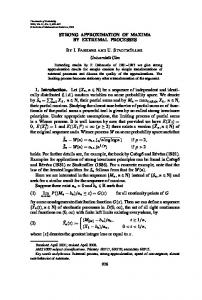
momentum error: � ¼ 0:002 and � ¼ 0:01, as in the previous section. The solutions of the V-R differential equations display instabilities of the dispersion and envelope functions for all beam currents in UMER, particularly for � around 0.002, when the dispersion is mismatched by arbitrarily setting Dð0Þ ¼ 0 ¼ D0 ð0Þ. Figures 2(a)–2(c) show the results of these calculations for 0.6 mA, � ¼ 0:002 over two turns in UMER. As Fig. 2(a) shows, the dispersion of the mismatch case turns negative during the first turn and its peak value grows by a factor of 4 at the end of the second turn; by contrast, the matched dispersion [Dð0Þ ¼ 0:048, D0 ð0Þ ¼ �0:16] remains positive and with a constant peak value of about 0.1 m. In Figs. 2(b), 2(b), and 2(c), we show the mismatched and matched horizontal and vertical envelopes; clearly, the beam horizontal dimension turns unstable during the second turn. The calculations in ELEGANT under the same initial conditions, however, do not display the instabilities; instead, the dispersion and horizontal envelope dimension undergo initially large slow and fast oscillations whose amplitude decay but continue after two turns. The oscillations are expected from the lattice geometry and space charge too [see Eqs. (11a)–(11c)], but in ELEGANT
FIG. 2. Dispersion and beam envelopes over two turns in UMER from solutions of the V-R equations; matched and mismatched cases for 0.6 mA, � ¼ 0:002 are shown: (a) dispersion functions, (b) horizontal beam envelopes, and (c) vertical beam envelopes.
104202-8
SMOOTH APPROXIMATION MODEL OF DISPERSION WITH . . . Phys. Rev. ST Accel. Beams 14, 104202 (2011)
FIG. 3. Comparison of results from ELEGANT and V-R equations for the dispersion functions at 0.6 mA, � ¼ 0:002 in UMER (two turns) for (a) mismatched, and (b) near-matched conditions. The horizontal beam envelopes over one turn for near-matched conditions are shown in (c). The dispersion function from ELEGANT in (b) appears to be shifting ahead of the V-R curve, but the inset indicates that this is not the case.
they are further modified by an initially varying emittance as discussed in more detail below. The results from ELEGANT and V-R equations are shown in Figs. 3(a)–3(c); notice the close agreement between ELEGANT and V-R calculations for the dispersion function over the first 5 m or so, and the almost perfect agreement for the envelopes in Fig. 3(c) (vertical envelope not shown.) Figures 4(a)–4(c) show examples of calculations of dispersion in ELEGANT for 0.0, 0.6, 6.0, and 21 mA with � ¼ 0:002, 0.01; also shown are lines indicating average values from the smooth approximation as well as from solutions of the V-R differential equations. Notice the large jump in average dispersion from 6 to 21 mA at � ¼ 0:002. All calculations yield a significantly larger average dispersion for a combination of small � ( & 0:002) and large current; e.g., for 21 mA, � ¼ 0:002, we get D ¼ 0:37 m (ELEGANT), 0.42 m (SA), and D ¼ 0:31 m (V-R equations). Better agreement for the average dispersion is obtained among the three approaches if � ¼ 0:001 (results not shown in Fig. 4); at 21 mA, for example, we get D ¼ 0:47 m from both ELEGANT and SA, and D ¼ 0:40 m from the V-R equations.
To examine the assumption of rms emittance conservation that lead to the SA Eqs. (12a)–(12c), and that was also used when solving the V-R equations, we can estimate the difference between the generalized rms horizontal emittance �dx [introduced in [1] and given in Eq. (10)] and the standard horizontal rms emittance �x rms . Using the smooth approximation to set D0 ¼ 0 and �2x rms ¼ hx2 ihx02 i ¼ a2 hx02 i=4 in Eq. (10), we obtain �2dx ffi �2x rms ð1 � �2x Þ;
(23)
where �x ¼ 2�D=a. Therefore, the fractional difference can be approximated as �x rms � �dx �2 x: �x rms 2
(24)
From either Eq. (23) or Eq. (24), we find that the fractional difference between �dx and �x rms is from around 1% at low current (0.6 mA) to 5% at high current (21 mA) if � ¼ 0:002, and from 10% to 30% (low to high current) if � ¼ 0:01. Therefore, the assumption that �x rms is conserved is
104202-9
S. BERNAL et al.
Phys. Rev. ST Accel. Beams 14, 104202 (2011)
FIG. 4. Dispersion functions with space charge over two turns in UMER from ELEGANT code: (a), (b) 0.0, 0.6, and 6.0 mA at 10 keV; (c) 21 mA at 10 keV. The solid black lines represent results from the smooth approximation [Eqs. (12a)–(12c)], while the broken lines indicate results from the V-R differential equations. Notice the different vertical scale in (c).
good for small momentum error but only fair for a combination of large momentum error and high space charge. From Figs. 4(a)–4(c), it is clear that the maximum dispersion can be a factor of 2, approximately, larger than the average dispersion during the first turn before the dispersion oscillations settle to an almost constant amplitude. The initial slow and large oscillations of the dispersion function are directly related to the (horizontal) emittance oscillations as can be seen from Eq. (10) above; the frequency of those oscillations can also be easily computed from Eq. (11a) using the average values of the matched envelopes X and Y (a and b) and the SA value of the external focusing constant kx0 . These oscillations are described also by Venturini in his Ph.D. thesis [14] and in a PAC99 paper [20] for space charge dominated beam transport in UMER with 100 mA and � ¼ 0:015. We obtain qualitatively similar results as illustrated in Fig. 5(a), where the dispersion and standard rms horizontal and vertical emittances (normalized to the initial values) from calculations with ELEGANT are plotted over two turns for
6.0 mA and � ¼ 0:010. The horizontal component of the beam envelope also evolves initially with slow oscillations coupled to the emittance oscillations, but not as strongly as the dispersion function; this is illustrated in Fig. 5(b). The decay of the slow oscillations of the horizontal emittance in approximately one turn is also in agreement with the WARP simulations presented in [14,20]. However, there are obvious differences between our results and Venturini et al. calculations, likely stemming from the different tune depression, space charge models, and mismatch conditions; in particular, the vertical emittance in the calculations from ELEGANT grows by less than 10%, while it more than doubles in the WARP calculation. In both sets of calculations, though, coupling of the two transverse directions, unavoidable in an alternating gradient lattice and modified by dispersion, as well as nonlinear space charge forces may drive the horizontal and vertical emittances closer together after the initial jump in the horizontal emittance from mismatched dispersion and/or envelope functions. The small-amplitude residual oscillations in the horizontal and vertical emittances
104202-10
SMOOTH APPROXIMATION MODEL OF DISPERSION WITH . . . Phys. Rev. ST Accel. Beams 14, 104202 (2011)
FIG. 5. Evolution of (a) dispersion and (b) horizontal envelope functions (red curves) and standard rms horizontal (blue) and vertical (black) emittances, normalized to initial values, from ELEGANT calculations for 6 mA, � ¼ 0:01 over two turns in UMER. The initial large oscillations occur even for initial dispersion/envelope values that are not far from matching conditions.
observed after about one turn [Fig. 5(a)] are related to envelope mismatch for space charge dominated transport, but are also affected by the order of the matrix calculations in ELEGANT as discussed in the Appendix. The large average dispersion obtained in cases of small � and large current do not lead to large displacement of off-momentum particles relative to the reference orbit or to significant beam size increase. Thus, the product D� is moderate, only about 0.8–2.0 mm, as obtained from the average and maximum dispersion for 21 mA, � ¼ 0:002 [Fig. 4(c) for 21 mA]. As expected, the effect on the average beam horizontal dimension is also small for � ¼ 0:002: a=aS ¼ 1:01; but significant at � ¼ 0:01: a=aS ¼ 1:11 (see Table I). Additional ELEGANT vs V-R equation calculations of dispersion are shown in Figs. 6(a) and 6(b), for 0.6 and 6.0 mA at � ¼ 0:01. Notice that, despite appearances, the dispersion functions are not ‘‘out of phase’’ relative to each other; it is only the slow (‘‘amplitude’’) oscillations that are
FIG. 6. Dispersion functions (ELEGANT, solid curves; V-R equations, dotted curves) with space charge for (a) 0.6 mA and (b) 6.0 mA, at � ¼ 0:01 over two turns in UMER. The dispersion functions from ELEGANT appear to be shifting ahead of the V-R curves, but the inset in (a) indicates that this is not the case.
out of phase. The same feature can be seen in the dispersion curve shown in Fig. 3(b) for 0.6 mA, � ¼ 0:002. Furthermore, for high current and large momentum error [Figs. 6(b) and 4(c)], the slow oscillation structure is essentially lost after one turn in the calculations with ELEGANT, while the dispersion from the V-R equations displays the slow oscillations for two turns and beyond. With constant and fixed emittances in the two transverse planes, and near-matched values for the initial envelopes and dispersion functions, the dispersion from the V-R equations evolves evenly from the start. By contrast, the results of particle-tracking calculations in ELEGANT reflect, as already mentioned, the changing emittances as well as effects from nonlinear space charge and dispersion. Further, and as seen in Fig. 3(a), a changing emittance can provide a stabilizing effect on the dispersion, thus indicating that the V-R equations do not always provide
104202-11
S. BERNAL et al.
Phys. Rev. ST Accel. Beams 14, 104202 (2011)
an accurate prediction. The model based on the V-R equations could be improved, though, by implementing a varying standard rms emittance according to Eq. (10), but this is not straightforward as the latter equation involves a 4D phase-space average. To summarize the results, for low current (0.6 mA or less) and � ¼ 0:001–0:01, the smooth approximation (SA) predicts an average dispersion that agrees well with both ELEGANT calculations and solutions of the envelopedispersion equations of the V-R theory. For space charge dominated transport around 6 mA, we obtain fair agreement among the three approaches for estimating average dispersion, also in the range � ¼ 0:001–0:01. At larger current (21 mA), however, there is agreement between SA and ELEGANT only for small � ¼ 0:001; for larger momentum errors, SA yields values of average dispersion that are significantly larger ( * 30%) than those from ELEGANT or the V-R equations. As for the average beam horizontal dimension, the V-R equations yield values that are always larger (10%–20%) than SA results, while ELEGANT predicts values that fall between V-R and SA. A similar discrepancy between V-R and SA average beam horizontal dimension is observed with space charge but no dispersion [13]. The model of smooth focusing/dispersion used here to predict transverse effects is not obviously applicable to short bunches when additional and significant transverselongitudinal phenomena occur. Also problematic is the case of strong correlation of momentum spread with the bunch’s slice, as can be originated at the source and be modified by longitudinal space charge in, e.g., coasting beams. However, we can still apply the model in this latter case to the core of the bunch, or, in an ad hoc way, to the whole bunch in an average sense. In UMER, the actual uncorrelated energy spread may be closer to � ¼ 0:002 for low current and somewhat larger (� ¼ 0:005) for high current, but we have chosen to do calculations with � ¼ 0:01 to enhance the effects of dispersion and because this figure corresponds more closely to the correlated energy spread. Furthermore, the initially correlated energy spread of the UMER bunch could turn into uncorrelated energy spread, at least partially, as the bunch ends meet after a number of turns with accompanying free longitudinal expansion. In this regime, where the ring is filled with charge [31,32], the dispersion model presented here would be relevant. Another interesting possibility is to study the average beam dimensions as functions of rms incoherent energy spread, whereby the latter is manually controlled by special means, in order to test directly the range of validity of the SA model [Eq. (15)]; this study would be similar to one conducted in a solenoid channel to test a SA model of space charge without dispersion [12]. So far, our dispersion measurements in UMER have been limited to beam centroid dispersion (see Sec. II) for 0.6 and 6.0 mA, with results that are in fair agreement with the zero-current value [19]. Furthermore, we have not
addressed in this paper the important issue of dispersionenvelope matching involving a bending element before injection into UMER. Computational work that employs the V-R formalism, as well as particle-in-cell simulations, for dispersion matching in UMER has been published before [33], but experimental investigations are lacking. Before a dispersion section is implemented in UMER, however, we need to do measurements of beam size, emittance, and energy spread on a turn-by turn basis to ascertain the degree of mismatch. One difficulty in this regard is to separate the effects of envelope mismatch from those of dispersion mismatch. But measurements over the first turn are also important, as the results discussed above indicate that important phenomena occur over the first few depressed betatron wavelengths (first turn in UMER) when the beam dispersion and transverse beam size relax from mismatch conditions. Needless to say, additional theoretical work is also required to extend the treatment of dispersion and space charge to bunched beams, perhaps including longitudinal space charge in a self-consistent 6D model. Finally, the calculations of space charge with ELEGANT can be improved and should be systematically compared with particle-in-cell simulations. VI. SUMMARY AND CONCLUSIONS We have presented a smooth approximation treatment of linear dispersion and space charge based on the theory developed by Venturini and Reiser [1]. The smooth approximation consists in replacing the discrete lattice of focusing and bending elements with uniform focusing and bending. Further, we have assumed that both dispersion and beam envelopes are matched, or nearly so, in an rms sense, and that the standard rms emittance is conserved. Under these conditions, we obtain a simple expression for the horizontal beam dimension as a function of tune depression and a dispersion-related parameter. We also introduce an intensity parameter to characterize beam transport with both dispersion and space charge over a broad range of beam and lattice parameters. We have applied the theory to beam transport in UMER and compared the results of average dispersion and beam dimensions with direct calculations using the VenturiniReiser original dispersion-envelope equations as well as with tracking of particles in the matrix code ELEGANT. We have shown that the smooth approximation of dispersion/ space charge provides simple and useful scaling relationships applicable to UMER and other machines. ACKNOWLEDGMENTS We are thankful to Max Cornacchia for his expert advice and constant help with the code ELEGANT, as well as for many useful discussions. We also benefited from discussions with Marco Venturini and Dave Sutter. The work is supported by the U.S. Department of Energy.
104202-12
SMOOTH APPROXIMATION MODEL OF DISPERSION WITH . . . Phys. Rev. ST Accel. Beams 14, 104202 (2011) APPENDIX: SPACE CHARGE IN ELEGANT
space charge kicks; thus, we find good agreement with for rms beam envelopes at 0.6 and 6.0 mA over one superperiod. For longer distances, the varying emittance in ELEGANT (see below) alters the agreement, but not significantly. We emphasize that only transverse space charge is included for the calculations presented in this paper. Furthermore, an improved (but considerably more complicated) space charge calculation in ELEGANT is possible if we concentrate on the effects on a center slice in the bunch [37] instead of trying to compensate for the s-position (slice) dependence of the space charge kicks along the bunch. Before doing dispersion calculations with space charge in ELEGANT, we verify the space charge model in the case of no momentum error. For this, we compare the rms envelopes that result from solving the V-R equations (with TRACE3D-derived initial conditions) and from tracking particles to build the envelopes in ELEGANT. Figures 7(a) TRACE3D
We do zero-current calculations of dispersion and envelopes in ELEGANT and compare the results with those from the V-R equations and from the standard smooth approximation. The zero-current case leads to average dispersion values of 0.049 m from ELEGANT and the V-R equations at an operating tune 0 ¼ 6:37. The average dispersion from simple theory, on the other hand, yields D0 ¼ �= 20 ¼ 0:045 m. The zero-current matched dispersion, i.e., the periodic lattice dispersion, is calculated automatically in ELEGANT, while in MATHEMATICA’s implementation of the V-R equations we adjust Dð0Þ and D0 ð0Þ for obtaining matched envelopes and dispersion. The two solutions for lattice dispersion are virtually identical. Space charge is implemented in ELEGANT as a series of electrical and magnetic kicks applied after each element in the lattice [34]. In turn, these kicks are calculated based on a tri-Gaussian distribution bunch, which leads to a linear transverse space charge force for a long bunch. The linear space charge force depends on the beam transverse and longitudinal rms envelope sizes, �x;y;z {we use the notation of [34]; the �x;y correspond to our X=2, Y=2 of Eqs. (11a)– (11c), or a=2, b=2 in the smooth approximation}, as in other implementations of space charge (e.g. TRACE3D [35]) through factors of the form ½�z �x;y ð�x þ �y Þ��1 , but ELEGANT has an additional exponential factor expð�s2 =2�2z Þ. Therefore, to do calculations involving space charge in a continuous (DC) beam in ELEGANT that we can compare with corresponding calculations with the V-R equations, we need to carefully decide on the effective �z and charge per bunch, transverse phase-space distribution, longitudinal phase-space distribution, and number of particles. For the calculations of this paper we use a ‘‘hardedge’’ (rectangular) distribution for the longitudinal phase space (cutoff ¼ 1:73), and ‘‘uniform ellipse’’ for the transverse phase spaces (cutoff ¼ 1:0) [36]. The choice for the transverse distributions follows the concept of a projected 4D K-V distribution [7] on the x � x0 or y � y0 planes, which is the basis of the V-R equations and the model in TRACE3D. For the same reason, the initial emittance in ELEGANT is taken as the 4rms unnormalized emittance (edge or effective emittance). ELEGANT calculates the rms beam transverse dimensions of the initial K-V beam and uses these values for space charge evaluation with the triGaussian distribution. Since a ¼ 2�x , and b ¼ 2�y relate the uniform-ellipse semiaxes to the rms dimensions, we also pffiffiffiffiffiffi use a bunch’s length equal to 2�z ¼ 2l= 12 ¼ 3:38 m, where l ¼ 5:85 m is the length of a 100 ns bunch at 10 keV. With these choices and the full charge per bunch, the space charge kicks in ELEGANT and TRACE3D take the same form (with DC approximation in the case of TRACE3D [29]) except for the exponential factor mentioned above in the case of ELEGANT. The longer bunch assumed in ELEGANT apparently reduces the effect of the exponential factor on the
FIG. 7. Envelope functions from ELEGANT and the V-R equations with no dispersion, over one superperiod in UMER, for (a) 0.6 mA and (b) 6.0 mA. Notice that the scales between (a) and (b) differ by a factor of 2. See Table I for additional parameters.
104202-13
S. BERNAL et al.
Phys. Rev. ST Accel. Beams 14, 104202 (2011)
and 7(b) show the results for 0.6 and 6.0 mA over one superperiod (0.64 cm) in UMER. The small differences in modeling focusing and bending in the two approaches do not contribute significantly to the observed discrepancy in the envelopes; clearly, this discrepancy increases for higher beam current. The changing emittance in ELEGANT does not seem to explain the differences either, as the space charge effects are significantly higher at 6 and 21 mA than the emittance effects. Therefore, it is likely that our implementation of space charge calculations in ELEGANT introduces significant nonlinear effects at high current. As we discussed before, the horizontal geometric emittance calculated in ELEGANT displays large amplitude oscillations over about 1=2 turn particularly in the mismatch case with Dð0Þ ¼ 0, D0 ð0Þ ¼ 0. These oscillations are mostly due to dispersion mismatch and are reflected in the evolution of DðsÞ ¼ �16 =�66 and the horizontal envelope XðsÞ. For 6 mA, � ¼ 0:01, the final (after two turns) rms emittance is some 40% larger than the initial value. With better matching conditions, the initial emittance oscillation amplitude is reduced by a factor of 2, and the final rms emittance is 20% larger than the initial value [see Fig. 5(a)]. The smallamplitude residual oscillations in the emittances illustrated in Fig. 5 for 6 mA have a period of close to 1 m, which is also the wavelength of envelope oscillations from mismatch [7]. The same oscillations are seen regardless of the number of particles for tracking calculations when this number is equal to or greater than 50 000; however, the size of the momentum error as well as the order of the matrix calculations affect the character of the oscillations near the end of the run. For example, comparison of calculations over five turns with order 1 (linear) and 3 (maximum order) for 6 mA and � ¼ 0:01 show that the oscillations at turn 5 become smaller and fairly irregular for the nonlinear case; this is not unexpected as nonlinearities lead to more beam filamentation over longer distances [38]. For calculations with lower current (0.6 mA) and momentum error (� ¼ 0:002), on the other hand, no difference between the linear and nonlinear cases is observed in the long-term behavior of emittance; in this case, the (horizontal) emittance oscillations track closely the slow oscillations of the beam dispersion for the length of the calculation. A more systematic study of long-term emittance evolution in the presence of both space charge and dispersion is deferred to a future publication. To conclude, a simple implementation of space charge calculations in the matrix code ELEGANT provides valuable insights on the evolution of beam envelopes, dispersion, and emittance. We have shown examples from UMER, but the same tools should be applicable to existing or future rings.
[1] M. Venturini and M. Reiser, Phys. Rev. Lett. 81, 96 (1998). [2] S. Y. Lee and H. Okamoto, Phys. Rev. Lett. 80, 5133 (1998).
[3] T. Ohkawa and M. Ikegami, Nucl. Instrum. Methods Phys. Res., Sect. A 576, 274 (2007). [4] M. Ikegami, S. Machida, and T. Uesugi, Phys. Rev. ST Accel. Beams 2, 124201 (1999). [5] H. Okamoto and S. Machida, Nucl. Instrum. Methods Phys. Res., Sect. A 482, 65 (2002). [6] J. A. Holmes, J. D. Galambos, D. K. Olsen, and S. Y. Lee, in Proceedings of the 6th European Particle Accelerator Conference, Stockholm, 1998 (IOP, London, 1998), p. 279. [7] M. Reiser, Theory and Design of Charged Particle Beams (Wiley-VCH, Weinheim, 2008), 2nd ed. [8] R. C. Davidson and H. Qin, Physics of Intense Charged Particle Beams in High Energy Accelerators (Imperial College Press and World Scientific, Singapore, 2001). [9] J. J. Barnard, H. D. Shay, S. S. Yu, A. Friedman, and D. P. Grote, in 1992 Linear Accelerator Conference Proceedings, edited by C. R. Hoffman (AECL Research, Chalk River, Canada, 1992), p. 229. [10] J. J. Barnard, G. D. Craig, A. Friedman, D. P. Grote, B. Losic, and S. M. Lund, in Proceedings of the Workshop on Space Charge Physics in High Intensity Hadron Rings, AIP Conf. Proc. No. 448 (AIP, Woodbury, NY, 1998), p. 221. [11] R. C. Davidson, H. Qin, and P. J. Channell, Phys. Rev. ST Accel. Beams 2, 074401 (1999). [12] H. Suk, M. Reiser, J. G. Wang, and D. X. Wang, J. Appl. Phys. 76, 3970 (1994). [13] S. Bernal, H. Li, R. A. Kishek, B. Quinn, M. Walter, M. Reiser, P. G. O’Shea, and C. K. Allen, Phys. Rev. ST Accel. Beams 9, 064202 (2006). [14] M. Venturini, Ph.D. thesis, University of Maryland, College Park, MD, 1998. [15] S. Henderson, Technical Report No. SNS-100000000PL0001-R13, Spallation Neutron Source, U.S. Department of Energy, 2005. [16] M. Cornacchia and G. H. Rees, in Proceedings Heavy Ion Workshop (Report No. LBL-10301, 1979), edited by W. B. Hermannsfeldt [Lawrence Berkeley Laboratory (UC) and Stanford Linear Accelerator Center, 1979], p. 297. [17] We employ a Uþ ion beam with the following parameters: 10 GeV, 1 kA, �n ¼ 35:7 �m (normalized rms emittance), � ¼ 10�4 , average machine radius � ¼ 83 m, and operating tune 0 ¼ 8:3. We obtain in the smooth approximation: tune depression � ¼ 0:9, D0 ¼ 1:2 m, a0 ¼ 0:069 m, D ¼ 1:5 m, a ¼ 0:072 m. See also Ref. [16] and equations in Sec. IV. [18] A. Jackson, Technical Report No. LBL-29280, Lawrence Berkeley Laboratory, University of California, Berkeley, 2010. [19] S. Bernal, D. Sutter, B. Beaudoin, M. Cornacchia, K. Fiuza, I. Haber, R. Kishek, T. Koeth, M. Reiser, and P. OShea, in 14th Advanced Accelerator Concepts Workshop, AIP Conf. Proc. No. 1299, edited by S. H. Gold and G. S. Nusinovich (AIP, Melville, NY, 2010), p. 580. [20] M. Venturini, R. A. Kishek, and M. Reiser, in Proceedings of the 18th Particle Accelerator Conference, New York, 1999 (Brookhaven National Laboratory, Upton, NY, and IEEE, Piscataway, NJ, 1999). [21] The original equations are written in terms of rms beam dimensions, �x;y and rms emittances �x;y , in the original
104202-14
SMOOTH APPROXIMATION MODEL OF DISPERSION WITH . . . Phys. Rev. ST Accel. Beams 14, 104202 (2011)
[22]
[23]
[24]
[25] [26] [27] [28]
notation [1]. In Eqs. (11a)–(11c), on the other hand, X, Y � 2�x;y , �x;y � 4�x rms;y rms in our notation. A. Garren, in Proceedings of the Heavy Ion Fusion Workshop (Reports No. LBL-10301/SLAC-PUB 2575 and No. UC-28, 1979), edited by W. B. Hermannfeldt [Lawrence Berkeley Laboratory (UC) and Standford Linear Accelerator Center, 1979], pp. 397–402. The equivalence is seen if we identify: (i) the vertical beam size, whose variance is denoted by �y2 in Ref. [9], with the first term in our Eq. (15), (ii) �x2m with our D20 �2 , (iii) k=k�0 with �x� , and we set a ¼ b. In addition, the condition �20 � 1 is also stated in Ref. [9]. If we simply substitute D0 =�2x0 for D and �x0 for �x� in Eq. (15), we obtain a2 ¼ a20 =�x0 þ 4�2 D20 =�4x0 , which grossly overestimates ‘‘a’’ for small �x0 and large �, (e.g. 21 and 104 mA at � ¼ 0:01). However, the expression a2 ¼ a20 =�x0 þ 4�2 D20 =�2x0 is more accurate than Eq. (19) over the same range of standard tune depressions. H. Wiedemann, Particle Accelerator Physics (Springer, New York, 2007), 3rd ed., p. 261. S. Y. Lee, Accelerator Physics (World Scientific, Singapore, 2004), 2nd ed., p. 122. M. Borland, Technical Report No. LS-287, Argonne National Laboratory, 2000. D. Grote, A. Friedman, I. Haber, W. Fawley, and J. Vay, Nucl. Instrum. Methods Phys. Res., Sect. A 415, 428 (1998).
[29] G. H. Gillespie Associates Inc., Particle Beam Optics Laboratory version 3.0.1.0 (2010). [30] Wolfram MATHEMATICA 6.0, Wolfram Research Inc., 2007. [31] T. Koeth, B. Beaudoin, S. Bernal, I. Haber, R. A. Kishek, and P. OShea, in Proceedings of the 2011 Particle Accelerator Conference (IEEE, New York City, NY, 2011). [32] B. Beaudoin, S. Bernal, K. Fiuza, I. Haber, R. Kishek, T. Koeth, M. Reiser, D. Sutter, and P. OShea, in Proceedings of the 2011 Particle Accelerator Conference (Ref. [31]). [33] L. G. Vorobiev, X. Wu, and R. C. York, in Proceedings of the 2001 Particle Accelerator Conference, Chicago (IEEE, Piscataway, NJ, 2001), p. 3078. [34] A. Xiao, M. Borland, L. Emery, Y. Wang, and K. Y. Ng, in Proceedings of the 2007 Particle Accelerator Conference, Albuquerque, New Mexico (IEEE, Piscataway, NJ, 2007). [35] K. Crandall and D. P. Rusthoi, TRACE 3-D Documentation, Report No. LA-UR-97-886, Los Alamos National Laboratory, 1997. [36] M. Borland, Advanced Photon Source, Argonne National Laboratory, 2009. [37] M. Cornacchia (personnal communication). [38] We should note that we used the linear order for all calculations presented before for comparison with the linear V-R theory; however, the space charge calculations include nonlinear kicks.
104202-15