quality. The pixel frequency depends on the display resolution and the refresh rate, so it is evident that if a better resolution or a higher fresh rate is desired it will.
International Journal of Computer Applications (0975 – 8887) Volume 78 – No.13, September 2013
SoC Implementation of VGA Driver using Spartan 3AN Series FPGA Ramandeep Singh
Nikhil Ahuja
Assistant Professor, EECE Department ITM University, Gurgaon, India.
EECE Department, ITM University, Gurgaon, India
ABSTRACT As the microelectronic industry grows there has been an exponential increase in the importance of FPGAs in modern digital circuit design. FPGAs not only provided an advantage of being reconfigurable but also come in extremely small packaging. In this paper we use the Xilinx Spartan 3AN series FPGA and propose its use as part of a System on Chip controller for a Video Graphics Array (VGA), that serves as one of the most popular display units today.
not used. The need was to choose between the FPGA and the ASIC and the FPGA was selected due to its faster time to market, simpler design cycle and the option of field reprogramability.
3. COMPARISON BETWEEN DIFFERENT MEMBERS OF SPARTAN-3 FAMILY
THE THE
General Terms VLSI Design, FPGA
Keywords FPGA, VGA, SOC, Xilinx Spartan 3AN, RTL View.
1. INTRODUCTION The System involves the use of the Spartan 3AN Series FPGA board to drive the VGA monitor. Included in the system is also a means of providing external inputs to the FPGA via a switch panel and a series of LEDs which find use as status or error indicators. VHDL is used as the Hardware Definition Language which is synthesized and proper hardware is implemented using Xilinx ISE 12.4[1, 2].
2. COMPARISON BETWEEN FPGA, CPLD AND ASIC
Performance Power Consumption Test Development complexity Density Unit Cost Timing Iterations Design Effort
FPGA High
CPLD Low
ASIC High
High
Very High
Low
Very Low
High
Low
High High High Low
Low Low Very High High Nonvolatile Very High
Very High High Low Medium
Memory
Volatile
Security
Low
Both High
Table 1: Comparison between FPGA, CPLD and ASIC
The comparison indicates the low performance of the CPLD as compared to the FPGA and the ASIC so it was
Device System Gates Logic Cells Block RAM Bits Distributed RAM Bits Max Single Ended I/O Max Differential I/O
XC3S200
XC3S400
XC3S1000
XC3S1500
XC3S2000
200K
400K
1000K
1500K
2000K
4,320
8,064
17,280
29,952
46,080
216K
288K
432K
576K
720K
30K
56K
120K
208K
320K
173
264
391
487
712
76
116
175
221
312
Table 2: Comparison between different members of the Spartan- 3 family The table discusses some of the basic architectural and memory specifications of the Spartan 3 family member of FPGAs. These parameters especially play an important role in helping to determine the particular FPGA required for the desired application. Xilinx as a manufacturer makes available FPGAs with an array of configurations to facilitate users to make an informed choice. The XC3S700AN FPGA was used as it lies in an intermediate product range which is suitable for utilization for the purpose of developing a prototype for a basic driver for the VGA graphics. High performance is not a primary requirement and the memory available with this Xilinx FPGA is adequate as per the requirement. Xilinx provides an FPGA user development board which includes hardware blocks which may need to be interfaced with the FPGA. Out of the available blocks the VGA port, the LEDs and the push buttons are the ones that are required for the application.
20
International Journal of Computer Applications (0975 – 8887) Volume 78 – No.13, September 2013
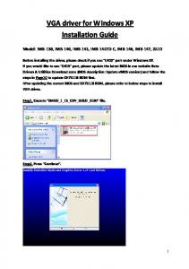
4. BLOCK DIAGRAM
All pixels are scanned in raster order at a frequency called pixel frequency. The whole image will be re-drawn at a rate determined by refresh rate in order to ensure the visual quality. The pixel frequency depends on the display resolution and the refresh rate, so it is evident that if a better resolution or a higher fresh rate is desired it will require a higher pixel frequency. [6] RGB signals are sent to appropriate pixels in rising clock pulse. The positions of the pixels are changed in each new frame, if movement of objects is desired. [7]A new frame is characterized by a rising Vertical sync pulse.
5.1 Horizontal Sync
Figure 1: Block Diagram of System VGA monitor controller, which is a logic circuit to control the VGA interface, can be easily realized by FPGA technology with a low cost and high flexibility. [3] The block diagram shows a VGA monitor connected to the FPGA board via a standard VGA cable using a 15 pin VGA connector on the board. A switch panel consisting of four switches is connected to the FPGA board. The application will involve using the FPGA to drive the VGA screen. A variety of patterns may be displayed on the screen and the switches could be utilized to manipulate the display pattern.
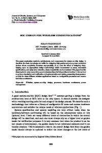
5. INTRODUCTION TO VGA The Video Graphics Array (VGA) is a display standard that was introduced in 1987[4]. The VGA screen that we intend to use is one which finds use in PCs today. Assuming that the VGA screen is based on the CRT technology, the following are certain important parameters that govern the display on the VGA screen.
The Horizontal Sync bit is used in order to indicate to the signal the beginning of a new line. The horizontal sync signal is a single short pulse which indicates the start of every line. The signal traces a line from one side to the other and a very fast retrace back to the first pixel of the next line.
5.2 Vertical Sync At the end of each frame of video there is a vertical sync signal that indicates when the next frame is going to start. The vertical sync signal tells the monitor to start displaying a new image or frame. In order to do so, the monitor starts in the upper left corner with pixel (0, 0). [8]
5.3 Refresh Rate This parameter specifies how fast the screen should be refreshed. For a human eye, the refresh rate must be at least 30 screens per second to make the motion appear to be continuous. To reduce flickering, the monitor usually has a much higher rate.
6. Introduction to FPGA Development Platform The following section provides an insight into the basic FPGA development platform used.
6.1 Spartan 3AN Series FPGA The Spartan®-3AN FPGA family combines the best attributes of a leading edge, low cost FPGA with nonvolatile technology across a broad range of densities. The Spartan-3AN FPGA family is excellent for spaceconstrained applications. [9] Features [9]
Figure 2: The VGA Monitor. The scanning starts from (0,0) and moves to the right and down until reaching column 639 and row 479. For a standard VGA Format the monitor screen contains 640 columns by 480 rows of picture elements called pixels. [5]
Integrated robust configuration memory Availability of up to 11K non-volatile user memory 20 years Flash memory data retention Configuration watchdog timer Suspend mode reduces system power consumption Full hot-swap compliance Abundant, flexible logic resources Eight global clocks and eight additional clocks per each half of device Abundant low-skew routing
21
International Journal of Computer Applications (0975 – 8887) Volume 78 – No.13, September 2013
6.2 Connector The Spartan 3AN FPGA Starter Kit board includes a VGA display port via a standard high-density HD-DB15 female connector.
Each LED has one side connected to ground and the other side connected to a pin on the device via a 390Ω current limiting resistor. For lighting an individual LED, it is required to drive the associated FPGA control signal High The UCF location constraints of the eight LEDs are mentioned below, along with the I/O pin assignment and the I/O standard used. NET "LED" LOC = "W21" | IOSTANDARD = LVCMOS33 | SLEW = SLOW | DRIVE = 8; NET "LED" LOC = "Y22" | IOSTANDARD = LVCMOS33 | SLEW = SLOW | DRIVE = 8; NET "LED" LOC = "V20" | IOSTANDARD = LVCMOS33 | SLEW = SLOW | DRIVE = 8; NET "LED" LOC = "V19" | IOSTANDARD = LVCMOS33 | SLEW = SLOW | DRIVE = 8; NET "LED" LOC = "U19" | IOSTANDARD = LVCMOS33 | SLEW = SLOW | DRIVE = 8; NET "LED" LOC = "U20" | IOSTANDARD = LVCMOS33 | SLEW = SLOW | DRIVE = 8;
Figure 3: Standard HD-DB15 female connector, location on board and connection diagram [10] There are three data signals for red, green and blue which control the color and two control signals horizontal synchronization and vertical synchronization signals [11]. The FPGA is capable of directly driving the five VGA signals via resistors. The red, green, and blue signals have four outputs from the FPGA that feed a resistor-divider tree.
6.3 Discrete LEDs The Spartan 3AN Starter Kit board has eight individual surface-mount LEDs located immediately above the slide switches as shown in the figure. The LEDs are labeled LED7 through LED0. [10]
NET "LED" LOC = "T19" | IOSTANDARD = LVCMOS33 | SLEW = SLOW | DRIVE = 8; NET "LED" LOC = "R20" | IOSTANDARD = LVCMOS33 | SLEW = SLOW | DRIVE = 8; [12]
6.4 Switch Panel The Spartan 3AN Starter Kit Board has available four momentary contact push button switches. These switches are located at the lower right corner of the board and are labeled BTN_NORTH, BTN_SOUTH, BTN_EAST and BTN_WEST as indicated in the figure. These buttons are used to provide an input signal to the FPGA and hence this panel of switches may be used as inputs to bring variations in the graphics displayed on the VGA.
LEDs can be used as indicators, for which they can be connected to the switches. These LEDs can be used to indicate errors as a result of which debugging the circuit would become convenient.
Figure 5: The four push button switches The UCF location constraints of the four push buttons are mentioned below, along with other necessary details Figure 4: The eight LEDs and four switches
NET "BTN_EAST" LOC = "T16" | IOSTANDARD = LVCMOS33 | PULLDOWN;
22
International Journal of Computer Applications (0975 – 8887) Volume 78 – No.13, September 2013
NET "BTN_NORTH" LOC = "T14" | IOSTANDARD = LVCMOS33 | PULLDOWN; NET "BTN_SOUTH" LOC = "T15" | IOSTANDARD = LVCMOS33 | PULLDOWN; NET "BTN_WEST" LOC = "U15" | IOSTANDARD = LVCMOS33 | PULLDOWN; [12]
7.1.3 Method of displaying a Text/Character[13] The letters of the alphabet as well as numbers and special characters can all be displayed using straight lines and curves. When looking to display text, the parameters that play an important role include the. The figure shows the letters V, G and A constituting VGA each displayed in an 8-by-8 pixel square.
7. Pattern Design in VGA The following section carries information regarding the methods used to display various kinds of graphics on screen.
7.1 Analysis of shape Formation 7.1.1 Method of displaying a rectangle/square A rectangular object can be defined by its boundary in terms of pixel coordinates on the screen. The figure illustrate the pixels that need to be lit in order to obtain the desired shapes.
Figure 6: Bit Map of a Square and a filled Square
7.1.2 Method of displaying a circle A circle will be defined in a square boundary that encloses it. The requirement for drawing a circle remains the definition of this square boundary. This boundary may be defined using the radius or the diameter of the circle as reference. Once the boundary is defined, the pixels are lit to display a circular shape. The figure illustrates a circle boundary and a filled circle drawn within an 8-by-8 pixel square.
Figure 8: Bit Map of the letters V, G and A each displayed in an 8-by-8 pixel square
8. GENERATED RTL VIEW The figure below is an indication of the RTL view for an FPGA designed to display a single horizontal line. The RTL view has been split into two sections and if interconnectivity is provided between the two blocks along the lines labeled from A to G, the complete RTL view would be available. The entire circuitry comprises various logic blocks that would combine to form the SoC for driving the VGA The RTL view indicates one input i.e. clk50_in which will come from the crystal on the board to the FPGA. There are also output signals for the red, green and blue components of the VGA input and the horizontal sync and vertical sync signals. The various blocks that may be required to display a single horizontal line include logic blocks that are determined by the HDL code that is written for the same. In the HDL code the pixels of the line are mentioned using greater than and less than operators to indicate the starting pixel and the ending pixel. Also included in the RTL view are basic logic gates, multiplexers and latches which enable decision making for the horizontal sync and the vertical sync signals that act as control signals for the VGA screen.
Figure 7: Bit Map of a Circle and a filled circle in an 8by-8 pixel Square
23
International Journal of Computer Applications (0975 – 8887) Volume 78 – No.13, September 2013
Figure 9a: RTL view of SOC for displaying a single horizontal line on VGA[14].
24
International Journal of Computer Applications (0975 – 8887) Volume 78 – No.13, September 2013
Figure 9b: RTL view of SOC for displaying a single horizontal line on VGA[14].
25
International Journal of Computer Applications (0975 – 8887) Volume 78 – No.13, September 2013 [4] Programming languages: A short history for
9. RESULTS The following are some of the outputs that were achieved on the implementation of the system on chip using VHDL. [1][15][16]
Figure 11: Display of box on VGA using the SOC
Figure 12: Display of characters on VGA using the SOC
Economists, Marc Nerlove, Department of Agricultural and Resource Economics, University of Maryland, College Park, Journal of Economic and Social Measurement Vol. 29 pp. 189–203 (2004) [5] Building a VGA monitor controller by Enoch Hwang, Nov 2004, www.circuitcellar.com [6] Ashish B. Pasaya, Kiritkumar R. Bhatt “Implementing VGA Application on FPGA using an Innovative Algorithm with the help of NIOS-II,” International Journal of Computational Engineering Research IJCER | May-June 2012 | Vol. 2 | Issue No.3 |pp. 771775 [7] Punj Pokharel, Binod Bhatta, Anand D. Darji, “Optimized Drivers for PS/2 and VGA using HDL,” Department of Electronics and Communication Engineering, Sardar Vallabbhhai National Institute of Technology, Surat, IEEE International Conference on Computer Science and Automation Engineering (CSAE), Vol:4| June, 2011 [8] A VGA Controller by Eduardo Sanchez, Ecole Polytechnique Fédérale de Laussane [9] Xilinx. Spartan-3E FPGA Family: Data Sheet. Technical report, August 2009.
Figure 12: Display of multi-colored boxes in various sizes on VGA using the SOC
10. ACKNOWLEDGMENTS Thanks to the Department of Electrical Electronics and Communication Engineering (EECE), at ITM University, Gurgaon for the use of its laboratories and resources that were made available for carrying out the above said research.
11. CONCLUSIONS The system on chip for the implementation of a VGA driver on the FPGA has been designed and synthesized for various different graphics which include shapes, text and graphics in motion using Xilinx ISE Design Suite 12.4 and the Spartan-3A/3AN FPGA Starter Kit\Board.
12. REFERENCES [1] IEEE Standard VHDL Reference Manual [2] Xilinx Inc. “ISE Design Suite 12.4 Release Notes an Installation Guide”, www.xilinx.com [3] Van-Huan Tran, Xuan-Tu Tran “An Efficient Architecture Design for VGA Monitor Controller,” SIS Laboratory, University of Engineering and Technology, VNU Hanoi, International Conference on Consumer Electronics, Communications and Networks (CECNet), April 2011.
[10] Spartan-3A/3AN FPGA Starter Kit\Board User Guide. [11] Guohui Wang and Yong Guan, “Designing of VGA Character String Display Module Base on FPGA”, IEEE Conference on Intelligent Ubiquitous Computing and Education, 2009 [12] Spartan-3A/3AN FPGA UCF Constraints File for the Starter Kit Board [13] Kai Liu, Yuliang Yang, Yanlin Zhu “Tetris game design based on the FPGA,” Dept. of Communication Engineering, School of Computer & Communication Engineering, USTB, Beijing, China, 2nd International Conference on Consumer Electronics, Communications and Networks (CECNet), April 2012. [14] Ramneet Kaur and Balwinder Singh ,”Design and Implementation of Car Parking System on FPGA,” Academic and Consultancy Services-Division, Centre for Development of Advanced Computing(C-DAC), Mohali, International Journal of VLSI design & Communication Systems (VLSICS) Vol.4, No.3, June 2013 [15] Circuit Design with VHDL by Volnei A. Pedroni, MIT [16] FPGA Prototyping by VHDL examples by Pong P. Chu
26