ICONS 2011 : The Sixth International Conference on Systems
Implementation of MCU Invariant I2C Slave Driver Using Bit Banging Arindam Halder, Ranjan Dasgupta
Jayakar Chepada, Nrusingh Prasad Dash
Innovation Lab, TATA Consultancy Services, Ltd. Kolkata, India
[email protected],
[email protected]
Innovation Lab, TATA Consultancy Services, Ltd. Kolkata, India
[email protected],
[email protected]
Abstract—The paper gives an overview of programming I2C slave device using bit banging method implemented in C programming language. In Microcontroller Unit (MCU) based tiny embedded system, with no built in universal serial communication (e.g., I2C, SPI, etc.) hardware engine support, bit banging method is the most efficient technique for handling any such communication. Finally, the paper states and demonstrates a solution of I2C communication between two devices as a case study. Keywords- I2C; Bit Banging; SPI; MCU; EEPROM.
I.
INTRODUCTION
Philips Semiconductors had developed the I2C protocol over 20 years ago and has an extensive collection of specific usage across several general purpose devices. The I2C-bus supports two wires, serial data (SDA) and serial clock (SCL), it carries the information between the devices connected to the bus. Each device is recognized by a unique 7-bit address and can operate as either a transmitter or a receiver, depending on the function of the device [2], [6]. Sometimes, processors do not have built in hardware support for the universal serial communication. In such case, design your own code to implement serial communication, which is known as bit banging. For example, the MSP430F1232 MCU does not have any kind of built in hardware serial communication support. Therefore, to add any I2C serial device in a project based on this MCU, you have to create code to handle the communication. So, the challenge is to write bit banging I2C slave driver using C programming language. The Slave will be synchronized by the master clock, and the data portion will be driven by either the master or the slave. The synchronization part is taken care by the port pin interrupts of SCL and SDA. This implementation is briefly given in the case study and in the code implementation (Appendix). The advantage to design your own code is that, you can add the I2C serial communication to any microcontroller. The data transfer between any two microcontrollers can be achieved by using this code. A microcontroller can also use this code to communicate with any other devices, which are on the same single board (e.g., EEPROM, etc.).
Copyright (c) IARIA, 2011
ISBN:978-1-61208-114-4
II.
PROTOCOL SPECIFICATION
In I2C protocol, a master is the device which initiates a data transfer on the bus and generates the clock signals to permit that transfer. At that time, any device address is considered as a slave. During the I2C communication, unique situations arise, which are defined as START and STOP conditions (Figure 1). A HIGH to LOW transition on the SDA line, while SCL is HIGH, is one such unique case. This situation indicates a START condition. A LOW to HIGH transition on the SDA line, while SCL is HIGH, defines a STOP condition.
SDA S SCL
P
1-7
8
1-7
9
8
ADD
W/R
ACK
Figure 1.
9
9
9 DATA
Data transfer on I2C bus
Every byte put on the SDA line must be 8-bit long. Each byte has to be followed by an acknowledgement bit. The data is transferred with the most significant bit (MSB) first. The transmitter releases the SDA line (HIGH) during the acknowledge clock pulse. The receiver must pull down the SDA line during the acknowledge clock pulse, so that, it remains stable LOW during the HIGH period of this clock pulse (Figure 1). After START condition, a slave address is sent. In 7 bit long, followed by an eighth bit, which is a data direction bit (R/W) - a ‘zero’ indicates a transmission (WRITE), a ‘one’ indicates a request for data (READ) (Figures 2 and 3). After the address byte, the data to be read or write according to the data direction bit, are sent. This way, data transmission happens until a stop condition occurs.
1
ICONS 2011 : The Sixth International Conference on Systems
S
SLAVE ADDRESS
R/W
A
DATA
A
P
A From master to Slave
S: Start bit
P: Stop bit
From slave to master
A: Acknowledgement
Figure 2. A master – transmitter addressing a slave receiver with 7 bit address
S
SLAVE ADDRESS
R/W
A
DATA
A
P
Figure 3. A master reads a slave immediately after the first byte
III.
CASE STUDY
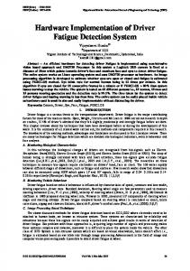
In our implementation, TI Davinci (DM6446) processor acts as an I2C master and MSP430 as an I2C slave device. The MCU I/O port pin P1.1 is configured as SCL and P2.1 as SDA. Both the pins are interrupt enabled. The master uses standard-mode of I2C communication, with its data transfer rate of up to 100 kbps and 7-bit addressing mode. To maintain the same bit rate in the slave side, we use Timer A of MSP430. Timer A has interrupt capabilities and it may be generated from the counter on overflow conditions. SCL
Davinci (DM6446 )
SDA
MSP430
dataline (SDA) will be controlled by the master or the slave as per the requirement. Here SCL will be captured by the __interrupt void Port_1(void) interrupt function and SDA will be taken care by the __interrupt void Port_2(void) interrupt function (see Appendix). SDA interrupt is used for detecting start and stop conditions of the I2C communication. This also detects repeated start condition. There are 4 states considered for the slave device 1. SLAVE_ADDRESS_RECEIVE 2. SLAVE_NOTMY_ADDRESS 3. SLAVE_DATA_RECEIVE 4. SLAVE_DATA_TRANSMIT Here, both the high to low transition and low to high transition on the SCL line are taken care. The initial state is SLAVE_ADDRESS_RECEIVE. Two counters, rising edge counter and falling edge counter are used to call specific function after specific number of bits received or transmitted. In low to high transition of the SCL line, PORT 2 (SDA) values are captured, enabling SDA interrupt to capture repeated start or stop condition from the master, and the SCL line are configured for high to low transition. In high to low transition of the SCL line, captured value is processed and the SDA interrupt is disabled. IAR Embedded workbench IDE (Integrated Development Environment) is used to develop and compiles the code. MSP430 USB-Debug-Interface is used for porting the source code to the microcontroller. V.
IR Reception Figure 4. I2C bit banging implementation between Davinci processor and MSP430
IV.
CODE IMPLEMENTATION
We have written the source code using C programming language. Most of the time, the assembly language code is more difficult to be understand, where as in C programming language it is much easier. But the most challenging thing is the performance. It should perform like the microcontroller has inbuilt hardware I2C engine. In source code, we call function init_i2c(i2c_read_byte). This function initializes the port pin for i2c slave and registers a callback function i2c_read_byte, which will process the data after receiving or before transmitting (see Appendix). MSP430_SWI2CSV_init() calls a function named resetSWI2C. resetSWI2C function is used several times in the code to reset the I2C slave. The purpose of this function is to reinitialize the SCL and SDA pins. Here both the SCL and SDA are configured as input pin, where SCL will report an interruption on the transition from low to high, and SDA will report from high to low transition. This condition will be treated as a start condition of the I2C communication. The rest of the code will execute on the interrupt context. As per the I2C specification, the master has the bus control over I2C bus and it is a synchronous protocol, so the clock (SCL) will be controlled by the master only, and the
Copyright (c) IARIA, 2011
ISBN:978-1-61208-114-4
CONCLUSION
The paper analyzes the simplicity concerns of writing I2C slave driver using bit banging method. An optimal and robust solution is implemented with a trade-off between speed and reliability. This generic approach can easily be adapted to any embedded device. Apart from MSP430F1232, other microcontrollers, like PIC16F5x or AT89C2051, also do not have universal serial communication interface [7], [8]. This generic code can also be used to achieve serial I2C communication just by changing the timer of specific MCU, to maintain the bit rate and interrupt driven PORT pins of the SCL and the SDA. REFERENCES [1] [2] [3]
[4] [5] [6] [7]
http://www.dwhoffman.com/bit_banging [retrieved: December 2010] http://www.nxp.com/acrobat_download2/literature/9398/39340011.p df [retrieved: December 2010] http://focus.ti.com/mcu/docs/mcuprodtechdoc.tsp?sectionId=95&tabI d=1204&familyId=911&techDoc=6&docCategoryId=6&viewType= mostrecent [retrieved: December 2010] http://processors.wiki.ti.com/index.php/TMS320DM6446 [retrieved: November 2010] http://focus.ti.com/lit/wp/spry136/spry136.pdf [retrieved: November 2010] http://ics.nxp.com/support/documents/interface/pdf/an10216.pdf [retrieved: December 2010] http://ww1.microchip.com/downloads/en/devicedoc/41213C.pdf [retrieved: December 2010]
2
ICONS 2011 : The Sixth International Conference on Systems
[8]
http://www.atmel.com/dyn/resources/prod_documents/doc0368.pdf [retrieved: December 2010]
APPENDIX #define init_i2c(callback) do { MSP430_SWI2CSV_init(); regI2CCallBack(callback); } while(0)
\ \ \ \
void resetSWI2C(){ set_scl_output_low(); set_sda_output_low(); set_sda_input(); set_scl_input(); set_scl_rising_intr(); set_sda_falling_intr(); clear_scl_intr(); enable_scl_intr(); clear_sda_intr(); enable_sda_intr(); i2c_data=0; } #pragma vector=PORT1_VECTOR __interrupt void Port_1(void) // SCL { if(P1IN&BIT0) // Low to High (Rising Edge) { rising_edge_counter++; switch(i2c_flag) { case SLAVE_ADDRESS_RECEIVE: case SLAVE_NOTMY_ADDRESS: case SLAVE_DATA_RECEIVE: address_low_high1to9(); break; default: // SLAVE_DATA_TRANSMIT if(rising_edge_counter