that unifies EDA and SOA by introducing a development method taking ad- vantage of the .... develop applications for such a combined architecture. As a step ...
Institute of Architecture of Application Systems
SOEDA: A Methodology for Specification and Implementation of Applications on a Service-Oriented Event-Driven Architecture Matthias Wieland, Daniel Martin, Oliver Kopp, Frank Leymann Institute of Architecture of Application Systems University of Stuttgart Universit¨atsstraße 38, 70569 Stuttgart, Germany http://www.iaas.uni-stuttgart.de in: Proceedings of the 12th International Conference on Business Information Systems (BIS 2009). See also BibTEX entry below.
BibTEX: @inproceedings {INPROC-2009-09, author = {Matthias Wieland and Daniel Martin and Oliver Kopp and Frank Leymann}, title = {{SOEDA:} A Methodology for Specification and Implementation of Applications on a Service-Oriented Event-Driven Architecture}, booktitle = {Proceedings of the 12th International Conference on Business Information Systems (BIS 2009)}, address = {Poznan, Poland}, publisher = {Springer}, series = {Lecture Notes in Business Information Processing}, volume = {7}, month = {April}, year = {2009}, isbn = {978-3-540-79395-3}, keywords = {epk; epc; transformation; bpel; soa; eda; event driven architecture; cep; complex event processing}, cr-category = {H.4.1 Office Automation}, }
© 2009 Springer-Verlag.
See also LNCS-Homepage: http://www.springeronline.com/lncs
SOEDA: A Method for Specification and Implementation of Applications on a Service-Oriented Event-Driven Architecture Matthias Wieland, Daniel Martin, Oliver Kopp, and Frank Leymann IAAS, University of Stuttgart, Germany {wieland,martin,kopp,leymann}@iaas.uni-stuttgart.de
Abstract. Both Event-Driven Architecture (EDA) and Service-Oriented Architecture (SOA) are unique architectural styles widely used in today’s industries. However, they mostly exist as isolated systems that could greatly benefit from each other when being combined. This paper introduces SOEDA, an approach that unifies EDA and SOA by introducing a development method taking advantage of the unique properties of each architecture. The different steps of the method reach from abstract process specification over event and process implementation to the the final execution phase – described in an abstract manner and by means of an example. Resulting applications are based on state-of-the-art workflow technology using events to trigger the execution of individual business activities. Key words: complex events, EPC, BPEL, transformation, MDA
1 Introduction Events are a widely used abstraction to facilitate asynchronous communication in IT systems. Although the terminology varies slightly across different domains, the concept of an event and event communication are omnipresent. Events are used for disseminating information e.g. in mobile environments and sensor networks and for application integration through messaging middleware (cf. Enterprise Application Integration), and monitoring to control and govern large and diverse installations of IT infrastructure.On an abstract level, an event is defined as “any happening of interest in a computer system” [1], e.g. values reported by sensors, timers or generally any detectable state-change that can be described in a computer processable manner. The main characteristic of event-based system is its inherent asynchronous nature, decoupling sender (producer) and receiver (consumer) of an event in the dimensions of time, reference and location. With the rise of Radio-Frequency Identification (RFID) and the ubiquity of computing devices in industry, event-based systems gained a lot of attention in the area of manufacturing and retail e.g. in form of the METRO Future
2
Matthias Wieland et al.
Store1 . Event-based systems in production today are typically based on Event-Driven Architecture (EDA) [1], an architectural style that is centered around the notion of event and event processing. Naturally, industries also have a strong interest in Business Process Management (BPM) technology to align and support their business processes with IT infrastructure. Business processes are expressed using specialized languages such as the Web Service Business Process Execution Language [2] (WS-BPEL or BPEL for short) or EventDriven Process Chains (EPC) [3]. BPEL facilitates process execution by providing and standardizing execution semantics for orchestrating business activities. It defines the way in which basic services (business activities in the form Web Services) are used to build new, coarser grained services. E.g. a loan approval process orchestrates the basic services RiskAssessment, CreditCheck and IncomeReview. Since Web Services are an implementation of the SOA architectural style, process systems using BPEL as orchestration language are naturally embedded into an existing service oriented architecture implemented by Web Services. EPCs in contrast are mostly concerned with the modeling aspect of business processes, and therefore put an emphasis on being more easy to use and providing a standardized set of visualization elements, whereas not defining exact execution semantics. This brings them closer to non-technical thinking people who want to concentrate on the high-level process rather than on concrete execution, which stands in direct contrast to what BPEL provides.Typically, transformations are employed on the initial EPC to create a “skeleton” BPEL process that is then further refined by IT staff to make it finally executable. Clearly missing today is an unified architecture, combining event-driven and serviceoriented architectures to one coherent whole. This paper aims at filling this gap by introducing the unified architecture and method SOEDA. The key advantage of this method is the integration of the individual strengths of each: EDA-based systems provide the ability to flexibly react to ad-hoc changes, recognize situations, and the power to handle huge amounts of events and data streams; SOA-based systems provide standards compliance, interoperability and legacy system integration. The key element for integrating both approaches is the EPC modeling concept, where events are treated as “first class citizens”, i.e. the occurrence of events are fundamental elements of the business process. Each action is always triggered by one or more events; finishing an action again creates events to trigger further actions. This way of triggering actions is transformed to service calls, which are an integral part of the final process execution language: BPEL. The result is a coherent model that uses a standardized, event-centric business process notation (in the form of EPC) for modeling the initial process, which is then transformed into a service centric execution model (in the form of BPEL processes) for actual process enactment. Consequently, this paper is organized as follows: in Section 1.1 we provide an example scenario that is used throughout the paper to exemplify our approach. Related 1
http://www.future-store.org/
The SOEDA Method
3
work is discussed in Section 2, which is followed by our system’s architecture, given in Section 3. Next, the method, consisting of five steps is discussed in Section 4. Finally, Section 5 summarizes our findings and gives an outlook on future work. 1.1 Motivating Scenario
Cooling Process
Average Temperature > 25°
Average Temperature < 25°
Start Cooling
Stop Cooling
Air Conditioning System Turned Off
Stop Heating
Heating Turned Off
Heating Process
Average Temperature < 17°
Average Temperature > 17°
Start Heating
Maintenance Process Average Temperature AboveLimit (> 30°) Average Temperature Below Limit (< 10°)
XOR
XOR
Start Maintenance Process
Maintenance Successfully Completed XOR Temperarture Still Exeeds Prescriptive Limits
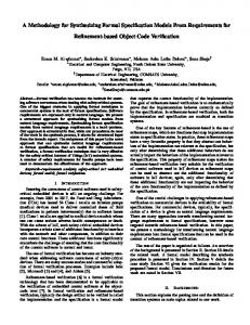
Fig. 1. Example Scenario: Temperature control processes based on sensor observation
In this section we introduce an example scenario to motivate in a practical way why the combination of event orientation and service orientation by using the SOEDA method is beneficial for designing workflow based applications. The example is used throughout the paper for a better understanding of the conceptual steps. The scenario given is one possible application field. An example of another field (production order processing) is presented in [4]. In pervasive computing many sensors and actors are deployed in the environment and can be accessed for observing or manipulating the state of the environment. This data can be used in a process as illustrated in the example scenario presented in Fig. 1. Here three processes are shown controlling room temperature to keep it between optimal values and thus forming a closed loop system: If the room temperature is to high the first process starts to lower it. If the room is to cold the second process is started. In the case the temperature exceeds a certain limit for the temperatures it is assumed that the climate system has a defect and the maintenance process is started. Such closed loop systems cannot be managed with a conventional workflow system due to the amount of messages per second (due to the high sampling rates and high
4
Matthias Wieland et al.
number of the installed sensors - each room has many temperature sensors that must be observed individually). Using the concepts described in this paper, BPM is enabled to manage those kinds of processes because stream handling and message reduction is done by complex event processing. Thus, the workflow system receives relevant messages only and can concentrate on handling the control flow.
2 Related Work Many works are available on combining Service-Oriented Architecture and Event-Driven Architecture (e.g. IBM: [5], HP: [6], Academic: [7]). In summary, they state that it is important to combine these architecture styles. They also state that it is difficult to develop applications for such a combined architecture. As a step towards solving that problem this paper presents in our knowledge SOEDA as the first method supporting the development of such applications. While there exist many island solutions for parts of our method. SOEDA builds on available solutions where possible. The Business Process Modeling Notation (BPMN, [8]) is a widely used graphical notation to model business processes. It exists in parallel to the EPC notation. In [9] the Business Event Modeling Notation (BEMN) is introduced; a language with a BPMN-inspired graphical notation to specify events. However, the link to an event infrastructure is not given. A taxonomy for model transformations is provided in [10]. The most important criteria is the distinction between horizontal and vertical transformation. In a horizontal transformation, the model is transformed to another model on the same abstraction level. In a vertical transformation, the target model resides on a different level of abstraction. In general, transformations of unmarked EPCs are horizontal transformations, whereas transformations of marked EPCs are vertical transformations [11]. A general overview of all available transformations from EPCs to BPEL and their classification using the taxonomy of [10] is given in [11]. In general, all the transformations ignore intermediate events. The only exception is [12], which distinguishes between data-based XOR-splits and event-based XOR-splits, but without stating how events are received from an infrastructure. The most recent work on mapping graphical notations to BPEL is presented in [13]. There, BPMN is mapped to BPEL by building a tree of structures in the graph. The type of each structure can be determined by applying the technique presented in [14]. We reuse these techniques in our approach and adapt it to handle EPCs.
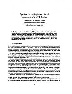
3 High-Level Architecture Fig. 2 depicts the overall architecture of the proposed SOEDA system: Workflow technology traditionally distinguishes between specification and execution layers, an
The SOEDA Method
Event e1
Specification layer
event specification
Business process relevant complex events e1
e2
Function f1 s1
automatic transformation
Execution layer
5
Event e2
event specification
BPEL engine
m1
f1e
s2
Low Level Events
CEP System event notification
Event e1: select avg(price) from OrderEvent.win:time (30 sec)
Fig. 2. System Overview
approach we follow in our architecture. To specify the workflow, designers use event driven process chains (EPCs). Thereafter the domain experts refine the events from the process definition using a domain-specific event description language shown on the right-hand side of Fig. 2 (CEP). Since the process itself is modeled on an abstract level, it must be possible to define events on the same abstract level in order to make it possible for the same person to define the process and the events, without the necessity to know details of either domain. Since EPCs and the domain specific CEP dialect are not directly executable, algorithms have to be used to transform both representations into executable workflows on the process side and into an executable CEP language on the event side. Event notifications from the event engine are then used to facilitate communication with the workflow execution engine (or with individual workflow instances, to be more precise). EPCs consist of four main elements: (i) events (depicted as hexagons), (ii) functions (depicted as rounded boxes), (iii) connectors (depicted as circles) and (iv) control-flow arcs. Events in EPCs are passive, i.e. they represent a state change in the system, but do not cause it (they do not provide decisions, but represent decisions taken). Events trigger functions, which are active elements that represent the actual work and again raise events upon completion. Connectors are used to join and split control flow, represented by edges in the EPC graph. An EPC starts and ends with one or more events, process control flow itself strictly follows an alternating sequence of functions and events, possibly with connectors specifying the kind of control flow join and split in between. Further details about EPCs are given in [3]. A BPEL process defines an orchestration of Web Services and consists of structured and basic activities. The actual business functions are not realized in BPEL itself, but by Web Services, where the business data is sent to and received from services using messages. Hence, the most important basic activities are invoke and receive. An invoke activity is used to send a message to a Web Service. A receive activity is used
6
Matthias Wieland et al.
to receive a message. The structured activity pick realizes an one-out-of-m choice of messages to receive: the first arrived message wins and the other messages are ignored at that activity. Control flow itself is either modeled block-structured using if and sequence activities or using graph-based constructs realized by the flow activity. The graph gets an intuitive execution semantics by marking non-reachable activities and paths as “dead”. The execution semantics itself is called “Dead-path Elimination”, which is formally defined in [15], specified for BPEL in [2] and explained in detail in [16]. A BPEL process does not need to be executable by itself. The BPEL specification offers to model abstract processes, which may hide operational details. One type of abstract processes are templates, where so called opaque activities can be used to model left-out behavior. We see these templates as abstract workflows. For a formal definition of EPC and BPEL syntax we have to refer the reader to the technical report [4] due to of space limitations in this paper. The necessary definitions regarding events are presented in Definition 1. Definition 1 (Event Sets). – Set of complex event names CE N consists of all names of complex events available in the system. They are identical to the names of the EPC events. – Set of complex event definitions CE D consists of descriptions for the deduction of all complex events using event adapters and conditions. – Set of complex event queries CE Q (CEP system) contains concrete implementations of all ced ∈ CE D for a specific complex event processing system, e.g. Esper2 . – Set of event sources ES contains all sensors or other raw source events producers. – Set of event adapters EA contains a set of Web Services that produce output only and make event sources technically accessible. EA publishes events of an ES which are received in a BPEL flow.
4 SOEDA Method This chapter presents the main contribution of the paper: A development method for workflow based applications based on event-driven service-oriented architectures. Due to different semantical layers and architecture styles, the development of such applications is very complex. To handle the complexity the SOEDA method builds on the MDA (Model-Driven Architecture) software design approach. That means the models are transformed from an computational independent model (CIM) to an platform independent model (PIM) and after that to an platform specific model (PSM). By that SOEDA can help saving development time, because the method provides as much as possible automated transformation for the different steps in Fig. 2. The main benefit results from the automatic transformation of the EPCs semantic business process specification to the very detailed abstract BPEL workflow artifacts. 2
http://esper.codehaus.org/
The SOEDA Method
7
Following subsections describe each transformation step of the method in detail. Here the CIM is represented by the EPC model because it is mainly natural language description for human to human communication (step 1). The PIM model is represented by the abstract BPEL code (step 3) and the wiring descriptions for the events (step 2, 4). The PSM model at the end results from the transformation of the PIM using a concrete platform model (PM). In our case the PSM consists of the executable BPEL workflows, the deployment descriptors for a BPEL engine and the executable CEP queries e.g. for Esper (step 5). All examples shown in the following use the example EPC “Maintenance Process” in Fig. 1. Step 1: Process Definition: The first step is the creation of the EPC specification by domain experts. For this task any EPC modeling tool, such as the ARIS toolset or Oryx 3 , can be used. We propose to use EPC as high level process definition language because it provides events as an integral part. That has the big advantage in contrast to other modeling languages like for example BPMN that an alternation between event based processing and workflow based service oriented control flow is prescribed by the process model. Example for Step 1: A sample EPC model is presented in Fig. 1. Step 2: Complex Event Extraction: The second step is the automatic extraction of all event names from the EPC specification (EEPC ). Event names are used as names (CE N ) for the complex event definitions (CE D ) that are defined in step 4. The complex events are deducted from the available event sources. In the execution phase these events are the messages the workflow is waiting to be notified of in a receive activity. Example for Step 2: CE N =EEPC ⇐⇒ CE N ={AverageTemperatureBelowLimit, AverageTemperatureAboveLimit, TemperartureStillExeedsPrescriptiveLimits, MaintenanceSuccessfullyCompleted} Step 3: Process to Workflow Transformation: The third step is the transformation of EPC control flow to an abstract BPEL flow. A main goal of the transformation is that both control flows have a similar structure to enable domain experts to understand the executed BPEL workflows due to the similarity to the EPCs they modeled as specification. This allows business activity monitoring to be done directly in the BPEL flow without additional efforts. The main transformation idea is to map EPC functions to opaque activities and EPC events to message receive activities. Each opaqueActivity has to be manually refined in the executable completion. The message receiving constructs are directly executable. Graphs are enforced to be acyclic in BPEL workflows. To express loops, the repeatUntil and while activities are offered. In addition, a choice between multiple incoming messages has to be modeled by a pick activity. In contrast to a BPEL workflow, an EPCs is allowed to be a cyclic graph. To map EPCs to BPEL workflows, we keep the original graph structure as much as possible in the resulting BPEL workflow. To detect 3
http://www.oryx-editor.org/try
8
Matthias Wieland et al. Function f1
Event e1
Fig. 3. General idea of the transformation
the structures which have to be mapped to the block-structures offered by BPEL, we combine the techniques presented in [13] and [14]. [13] presents a technique to identify the structure of a graph, called “Process Structure Tree” (PST). The structures of the tree can be classified as types such as repeat-until-loop by using the technique presented in [14]. In case a structure cannot directly be expressed using BPEL constructs, we map this structure into an opaqueActivity. We use transformation patterns to transform identified structures. A transformation pattern consists of the source EPC structure and target BPEL structure. In the following, we present the mapping concept as well as one example transformation pattern. Further patterns and technical details are presented in [4]. Sequence RepeatUntil
Pick
e3
e1 XOR
XOR
f1
XOR e4
e2
Fig. 4. Process Structure Tree for the Maintenance Process
The general idea is presented in Fig. 3: the EPC function f1 is transformed to an opaqueActivity and the event e1 is transformed to a receive. The opaqueActivity and the event are connected using a link l1, which takes no transition condition. The name of the link is made unique within the BPEL process. The name of the BPEL opaqueActivity is the camel case version of the name of the EPC function. The receive does not get a name assigned. The name of the partner link is always EventsPLT. The name of the operation is the camel case version of the event. The name of the output variable is Event, where is replaced by an unique number. If an event is used by a transformation pattern, the mapping of that event is defined by that pattern, as in the case of the start events and the repeat-until loop used in the maintenance process (Fig. 1). To determine structures, a process structure tree [13] is built (Fig. 4). The identified sequence is transformed to a flow activity, where the contained activities are connected using links. The pick-block at the beginning is
The SOEDA Method l1 XOR
SubStructure 1
Loop Event
XOR lm ... ln
li ... lj
Event em
Event ei Event ej
Event en lo
SubStructure o
........... ...
lp
SubStructure p
9
… …mapping of sub-structure 1… doRepeatUntil = true doRepeatUntil1 = false … transformation of other non-loop events … doRepeatUntil1 = false; EventEnHappened=true doRepeatUntil1
Fig. 5. Repeat-until transformation pattern (the syntax of the assign activity is simplified)
transformed to a pick activity. Repeat-until loops are transformed as shown in Fig. 5: to indicate whether the loop has to be run, the indicator variable doRepeatUntilLoop1 is used. Three types of events are distinguished: the loop event (Loop Event), end events (Events ei to ej) and intermediate events (Events em to en). In contrast to end events, intermediate events have successors. Each event is catched by a pick activity. If the event is the loop event, the indicator variable is set to true. If the event is an end event, the indicator variable is set to false and no further transformation action has to be taken. If the event is an intermediate event, the indicator variable is set to false and a Boolean variable (EventEnHappened) is set to true. This variable is used as transition condition on the link connecting the repeatUntil with the mapped sub-structure belonging to the event. Example for step 3: The generated BPEL template for the “Maintenance Process” is shown in Fig. 6, which is a screenshot of the BPEL file opened in the Eclipse BPEL designer4 . The two start events of the EPC are transformed to an BPEL pick, because they are connected by an “exclusive or”. The loop is represented in BPEL as repeatUntil, since it starts with an activity. It is important to note that the transformation is a vertical transformation, in the sense that not only the control flow structure is mapped, but also the events are enriched by a connection to Web Services. Step 4: CEP Rules Specification: Wiring of source-events to complex events, i.e. the specification of the rules how complex events are created, is defined using a dedicated event wiring tool. The resulting specification is targeted to communicate these complex event generation rules to a developer that implements code for the event system that 4
http://www.eclipse.org/bpel/
10
Matthias Wieland et al.
Fig. 6. Eclipse BPEL editor view of “Template-MaintenanceProcess.bpel”
aggregates basic events to the complex events with the semantics that were specified. Generally, the event definition is always a tree with the complex event as the root node and the source events or other complex events as leave nodes. Intermediary nodes are operators. Up to now a language such as BEMN [9] could be used. However, the event wiring tool also has to specify how correlation is initiated in the case of a start event and how events and process instances are correlated using e.g. a correlation ID. Please note that it is not necessary to have a dedicated modeling tool at hand in order to be able to carry out this task. Any graphical modeling tool that is able to draw simple graphs and annotate them with textual description suffices. Natural language is used for the definition of all CE D : Therefore, 1. Each ES needs to be identified, i.e. it must be clear which actual source of events (a sensor for instance) should be used. 2. Each arc has to denote a condition that is used to filter events flowing through. 3. OP may be any kind of functionality, e.g. a logical operator or set operation that performs actions on all incoming events. 4. Each complex event CE N therefore is specified through basic
The SOEDA Method
11
events and a combination of operators. All information necessary to deduct the complex event must be included.
Event Sources (Es) temperature sensor 2 temperature sensor 1
temp in °C
temp in °C
avg. last 20 sec.
> 30°
avg. last 50 sec.
> 30°
CED,1 (AverageTemperatureAboveLimit)
Complex Events (CEn) Average Temparature AboveLimit
Initiate Correlation using Temp Sensor ID
Fig. 7. Wiring of Source-Events to Complex-Events
Example for step 4: Fig. 7 shows an example wiring. Here event streams from two different temperature sensors (1 and 2) are emitted , filtered (for C◦ ), aggregated (for 20 and 50 sec.), and finally filtered again (average temp >30◦ ). Every event that passes through produces an ”AverageTemperatureAboveLimit” complex event. Step 5: Executable Completion: The last step is a purely technical step. This step should be done by IT experts hence only technical execution information has to be inserted. On the one hand all CE D definitions must be mapped to queries for the used CEP system (CE Q ). Also event adapters EA , possibly employing Common Base Events (CBE, [17]), for all needed event sources ES have to be provided (installed or implemented). On the other hand, the generated BPEL flow is a template which means it cannot be executed directly. The missing execution information and refinements needed for execution have to be added by the IT-expert: substitute all opaque activities, define variables and assigns for the process internal data flow, and last but not least selecting the Web Service interfaces (WSDL) that should be used in the invoke activities. Example for step 5: An complete example with executable BPEL code and WSDL definitions can be found in [4]. Due to space limitations it is not possible to go into further details in this paper.
5 Conclusion and Future Work We presented SOEDA, a new method that helps to cope with the yet unsolved challenge how to specify complex events and their effects on workflows. The method was illustrated by an example. Further prove for applicableness of the proposed method is shown in the technical report [4] by presenting a complete walkthrough of all steps based on two examples of contrary application areas. Regarding the mapping of EPC to BPEL, our
12
Matthias Wieland et al.
work combines the work of [13] and [14] to provide a complete mapping with support of loops and workflow start events. Future work is to do research on how provide good tool support for the presented method. There are different areas of tools that would help a domain expert to use the proposed method: first an integrated modeling tool that allows to model EPC processes, BPEL processes and transformation patterns. Secondly a complex event wiring tool that allows the specification of the complex events based on the available sensors.
References 1. G. Muehl, L. Fiege, and P. R. Pietzuch. Distributed Event-Based Systems. Springer Verlag, 2006. 2. OASIS. Web Services Business Process Execution Language Version 2.0. http://docs. oasis-open.org/wsbpel/2.0/wsbpel-v2.0.html, 4 2007. retrieved at 14.8.2007. 3. A.-W. Scheer, O. Thomas, and O. Adam. Process-Aware Information Systems: Bridging People and Software Through Process Technology, chapter Process Modeling Using EventDriven Process Chains, pages 119–146. Wiley & Sons, 2005. 4. M. Wieland et al. Events Make Workflows Really Useful. Technical report, University of Stuttgart, IAAS, Germany, 2008. http://www.informatik.uni-stuttgart.de/cgi-bin/ NCSTRL/NCSTRL_view.pl?id=TR-2008-09&engl=1. 5. J.-L. Mar´echaux. Combining Service-Oriented Architecture and Event-Driven Architecture using an Enterprise Service Bus. IBM Developer Works, 2006. 6. M. Wei, I. Ari, J. Li, and M. Dekhil. ReCEPtor: Sensing Complex Events in Data Streams for Service-Oriented Architectures. Technical report, HP, 2007. 7. Z. Laliwala and S. Chaudhary. Event-driven Service-Oriented Architecture. In ICSSSM. IEEE Computer Society, 2008. 8. Object Management Group. Business Process Modeling Notation, V1.1, 2008. 9. G. Decker, A. Grosskopf, and A. Barros. A Graphical Notation for Modeling Complex Events in Business Processes. In EDOC. IEEE Computer Society, 2007. 10. T. Mens and P. Van Gorp. A Taxonomy of Model Transformation. Electronic Notes in Theoretical Computer Science, 152:125–142, March 2006. 11. S. Stein, S. K¨ uhne, and K. Ivanov. Business to IT Transformations Revisited. In MDE4BPM, 2008. 12. J. Ziemann and J. Mendling. EPC-Based Modelling of BPEL Processes: a Pragmatic Transformation Approach. In MITIP, 2005. 13. J. Vanhatalo, H. V¨ olzer, and J. Koehler. The Refined Process Structure Tree. In BPM. Springer, 2008. 14. L. Garc´ıa-Ba˜ nuelos. Pattern Identification and Classification in the Translation from BPMN to BPEL. In On the Move to Meaningful Internet Systems. Springer, 2008. 15. F. Leymann and D. Roller. Production Workflow: Concepts and Techniques. Prentice Hall PTR, 2000. 16. F. Curbera et al. Exception Handling in the BPEL4WS Language. In BPM. Springer, 2003. 17. D. Bridgewater. Standardize messages with the Common Base Event model. IBM DeveloperWorks, 2004.