adoption of soft information forwarding at the relay nodes. The soft information at ... v-th time domain sample transmitted by the m-th node, with sample period Ts ...
Soft-decode-and-forward for Asynchronous Wireless Networks with Doubly-Selective Fading Jingxian Wu∗ Department of Electrical Engineering University of Arkansas, Fayetteville, AR 72701 Abstract— A new soft-decode-and-forward (SDF) relay strategy for asynchronous wireless networks is presented in this paper. Unlike most previous works that assume simplified or idealized channel conditions, the new SDF relay strategy is designed to operate in practical asynchronous wireless networks with doubly-selective (both time-selective and frequency selective) fading. To combat the impairments caused by doubly-selective fading, as well as to preserve the correlation between signals delivered by the source and the relay, the relay nodes perform soft decoding, and forward reliability information to destination. A block decision feedback equalizer (BDFE) is employed at relay nodes to extract the soft information from the distorted signals. Distributed orthogonal frequency division multiplexing (OFDM) is adopted to cope with node asynchronism and fading time dispersion. Distributed OFDM systems in the literature were usually developed based on the assumption of perfect decoding at relay nodes, and such unrealistic assumption is not required by the new SDF relay strategy. Simulation results show that the new SDF method can flexibly adapt to the dynamic signal qualities at relay nodes, and it always outperforms the decode-and-forward relay strategy with hard decoding at relay.
I. I NTRODUCTION A relay-enabled wireless network distributes information by utilizing intermediate wireless terminals as relay nodes between a source and a destination [1]. Due to channel distortion between the source and the relay, relay nodes usually forward a distorted version of the original information to the destination. The well studied amplify-and-forward (AF) [2] relay strategy forwards an amplified version of the signals received by the relay, and both the data components and the noise components are amplified during the process. Relay nodes employing decode-and-forward (DF) [3] deliver hard decoded information to the destination node. Detection errors made at relay nodes will propagate to the destination node and degrade the system performance. Therefore, the signal quality at relay nodes plays a critical role on the design of practical wireless networks. To cope with the dynamic signal quality at relay nodes, soft-decode-and-forward (SDF) relay strategies are proposed to combine the benefits of AF and DF [4], [5]. Relay nodes employing SDF will perform soft decoding and forward reliability information to the destination. SDF enjoys soft ∗ This work was supported in part by the Natinoal Science Foundation under Grant ECCS-0917041.
information representation of AF, and coding gain of DF. The SDF strategies proposed in [4] and [5] relay soft information in the form of log-likelihood ratio (LLR). The LLR-based relay strategy can only be used for systems with binary modulation. Most of the research on wireless networks assumes perfect synchronization among the wireless nodes, i.e., signals from different relay nodes will arrive at the destination at precisely the same time. However, the spatial distributed nature of wireless network makes it extremely difficult, if not impossible, to achieve exact synchronization among the wireless nodes. Motivated by the fact that relative delay among the wireless nodes results in an equivalent multipath channel, Mei et. al. [6] and Li et. al. [7] adopted a distributed orthogonal frequency division multiplexing (OFDM) scheme. The distributed OFDM methods in [6] and [7] are based on the assumption that the relay nodes can perfectly recover the original information. This can be achieved by silencing relay nodes with detection errors. All of the aforementioned works assume simplified or idealized channel conditions, such as additive white Gaussian noise (AWGN) channel [1], frequency-flat fading channel [4], [5], or quasi-static frequency-selective fading channel [7]. High mobility broadband communication targeted for future applications dictates an operation environment of doublyselective (both time-selective and frequency-selective) fading, which includes the effects of both fading time variation due to nodes movement, and fading time dispersion due to broadband communication. Doubly-selective fading contains the simplified channel models as special cases, but it is not a trivial extension, especially in the design of relay strategies. In this paper, we propose a new SDF relay strategy that can operate in asynchronous wireless networks with doublyselective fading. Similar to [6] and [7], it uses distributed OFDM to cope with the asynchronism among wireless nodes. However, it doesn’t require perfect relay detection due to the adoption of soft information forwarding at the relay nodes. The soft information at relay nodes is obtained by passing the received signals through a block decision feedback equalizers (BDFE) with minimum mean square error (MMSE) criterion. The BDFE can extract soft information and combat the impairments caused by doubly-selective fading. The soft decoder at the relay nodes preserves the correlation between signals delivered by the relay and the source, and it can flexibly adapt to the dynamic signal qualities at the relay nodes. In addition, it can be used for system with high level modulations. A suboptimum maximum likelihood decision rule is developed at
978-1-4244-4148-8/09/$25.00 ©2009 This full text paper was peer reviewed at the direction of IEEE Communications Society subject matter experts for publication in the IEEE "GLOBECOM" 2009 proceedings.
the destination by collecting information from both the source and relay nodes. II. D ISCRETE - TIME S YSTEM M ODEL Consider a wireless network with one source node, s, one destination node, d, and NR asynchronous relay nodes. The nodes are assumed to be half-duplex. The transmission is divided into two phases. In phase 1, source node broadcasts information to all the relay nodes and the destination node; in phase 2, all the relay nodes deliver their respectively decoded information to the destination node. It should be noted that due to the distorted observations at the relay nodes, the information transmitted by different relay nodes might be different. The wireless link between any transmitting-receiving nodes pair is assumed to experience doubly-selective fading. Define the composite impulse response (CIR) of the channel between the m-th transmitting node and the n-th receiving node as gmn (t, τ ) = pT (τ ) ⊗ ϕmn (t, τ ) ⊗ pR (τ ),
(1)
where ⊗ denotes time-varying convolution, pT (τ ) and pR (τ ) are the time-invariant impulse responses of transmit filter and receive filter, respectively, and ϕmn (t, τ ) is the time-varying impulse response of the physical fading, with t denoting time variation and τ time dispersion. It’s assumed that the channel keeps constant during the duration of the filters. With the CIR defined in (1), the signals at the output of the receive filter of the n-th receiving node can be represented as rn (t) =
NT +∞ � �
xm (v)gmn (t, t − vTs ) + zn (t),
(2)
m=1 v=−∞
where NT is the number of transmitting nodes, with NT = 1 during phase 1 and NT = NR during phase 2, xm (v) is the v-th time domain sample transmitted by the m-th node, with sample period Ts , and zn (t) = wn (t) ⊗ pR (t) is the noise component at the output of the receive filter, with wn (t) being the additive white Gaussian noise (AWGN) with variance σn2 . The output of the receive filter is sampled at instant vTs + τmn , and this leads to an equivalent discrete-time system, rn (v) =
NT � +∞ �
xm (v − l)gmn (v, l) + zn (v),
(3)
m=1 l=−∞
where τmn is the relative delay between nodes pair (m, n), rn (v) = rn (vTs + τmn ) and zn (v) = zn (vTs + τmn ) are the samples of the signal component and noise component, respectively, and the discrete-time CIR, gmn (v, l) = gmn (vTs + τmn , lTs + τmn ), is represented in the form of an infinite impulse response (IIR) tapped-delay-line filter with time-varying coefficients. If the receive filter satisfies Nyquist criterion, zn (v) is still zero-mean AWGN with variance σn2 . The relative nodes delay, τmn , is contributed by two factors, the clock difference among the nodes, and the distance difference among the transmitting-receiving pairs. The effect of τmn is incorporated in the representation of the discrete-time CIR, gmn (v, l). For channels experiencing wide sense stationary uncorrelated scattering (WSSUS) Rayleigh fading, gmn (v, l)
is zero-mean complex Gaussian distributed with correlation ∗ (v2 , l2 )] coefficient ρmn (v1 , l1 ; v2 , l2 ) = E [gmn (v1 , l1 )gmn calculated by [8] ρmn (v1 − v2 ; l1 , l2 ) = J0 (2πfd Ts (v1 − v2 )) · cmn (l1 , l2 ), (4) with
� +∞ cmn (l1 , l2 )= Rp (l1 Ts − μ)Rp∗(l2 Ts − μ)Gmn (μ + τmn )dμ, −∞
where J0 (x) is the zero-order Bessel function of the first kind, fd is the maximum Doppler spread, Rp (t) = pT (t) ⊗ pR (t), and � +∞Gmn (μ) is the normalized power delay profile with Gmn (μ)dμ = 1. It should be noted that the channel −∞ taps are mutually correlated even though the underlying fading undergoes uncorrelated scattering. The inter-tap correlation is caused by the time span of the transmit filter and the receiver filter, and it depends on the power delay profile and the relative node delay. With the correlation information given in (4), the power of the l-th channel tap is cmn (l, l). The time domain tails of the transmit filter and the receive filter usually fall off rapidly, and the physical channel impulse response, ϕmn (t, τ ), has finite support over τ . Thus, the channel tap power, cmn (l, l), decreases quickly as |l| increases. When cmn (l, l) is less than a threshold, the corresponding channel tap will have negligible effects on system performance and can thus be discarded. For this reason, the IIR channel can be truncated to a time-varying finite impulse response (FIR) channel, gmn (v, l), for l = 0, 1, · · · , Lmn − 1 1 , where Lmn is the equivalent channel length. The value of Lmn depends on the channel power delay profile, the transmit filter, the receive filter, and the relative delay, τmn . Due to the presence of τmn , we have Lmn > 1 even for a frequency-flat fading channel. III. S OFT-D ECODE - AND -F ORWARD The structure and operations of the new SDF relay strategy in an asynchronous wireless relay network with doublyselective fading are presented in this section. A. Distributed OFDM To cope with the fading time dispersion as well as the asynchronism among the spatially distributed wireless nodes, we employ distributed OFDM in the network. At the source node, N parallel data symbols, s = [s0 , s1 , · · · , sN ]T ∈ C N ×1 , with AT denoting matrix transpose, are modulated onto N orthonormal subcarriers with inverse discrete Fourier transform (IDFT). The time domain samples can be represented as x = FH s, where AH stands for matrix Hermitian, and F ∈ C N ×N is the normalized discrete Fourier transform (DFT) matrix � � 1 √ . with the (m, n)-th element being N exp −j2π (m−1)(n−1) N Cyclic prefix with length L = max Lmn is inserted before ∀(m,n)
the transmit filter as a guard interval between symbols. The space between two adjacent time domain samples is Ts = TN0 , with T0 being the symbol period. 1 The channel is assumed to be causal. Non-causal channel can always be converted to an equivalent causal channel by introducing delays at the receiver.
978-1-4244-4148-8/09/$25.00 ©2009 This full text paper was peer reviewed at the direction of IEEE Communications Society subject matter experts for publication in the IEEE "GLOBECOM" 2009 proceedings.
⎛ ⎜ ⎜ Gsn = ⎜ ⎝
0 gsn (0, 0) gsn (1, 1) gsn (1, 0) .. .. . . 0 ···
gsn (0, L − 1) 0 .. .
··· gsn (1, L − 1) .. .
gsn (0, 1) ··· .. .
0
gsn (N − 1,L − 1)
···
gsn (N − 1, 0)
After the removal of the cyclic prefix at the receiver, the time domain samples at the n-th Relay node during phase 1 can be represented as rn = Gsn · x + zn , for n = 1, · · · , NR ,
yn = Hsn · s + wn ,
(5)
ˆsn = Wsn yn − Bsn s,
(9)
and the corresponding error vector is en = Wsn yn − (Bsn + IN )s,
(10)
where IN is an N × N identity matrix. yn
Wsn
ˆn y
ˆsn −
(7)
where yn = Frn , wn = Fzn are the frequency domain signal vector and noise vector, respectively, and Hsn = FGsn FH is the frequency domain channel transition matrix between nodes s and n. The (i + 1, k + 1)-th element of Hsn is hsn (i, k) =
⎟ ⎟ ⎟ ⎠
The feedback filter is a strict upper triangular matrix with zero diagonal elements. Based on the assumption of correct detection, the decision vector can be expressed as
(6)
where rn = [rn (0), · · · , rn (N − 1)]T ∈ C N ×1 , zn = [zn (0), · · · , zn (N − 1)]T ∈ C N ×1 are the time domain signal vector and noise vector, respectively, and Gsn is the time domain channel transition matrix between the source node and the n-th relay node as defined in (5). Applying DFT over rn leads to the frequency domain system representation as
N −1 L−1 � �
⎞
··· ··· .. .
gsn (u, l)e−j2π N e−j2π lk
u(i−k) N
,
(8)
u=0 l=0
The non-diagonal elements of Hsn are caused by the Doppler shift due to the fading time variation. For quasi-static fading channel, Hsn degrades to a diagonal matrix. It’s assumed that the receiver has ideal knowledge of Hsn through channel estimation. B. Soft-Decode-and-Forward with BDFE The signals observed by the relay nodes are distorted by doubly-selective fading, Hsn , and noise, wn . Specifically, the presence of fading time variation destroys the orthogonality among the subcarriers, and introduces inter-carrier interference (ICI). In such context, the AF and DF relay strategies might not be able to extract the original information from the distorted signals. The operations at the relay nodes should be able to combat ICI, as well as to preserve the correlation between the signals delivered by the relay nodes and the source node. We propose to design a soft-decode-and-forward relay strategy that forwards soft reliability information to the destination. The soft information should meet two criteria. First, to solve the noise amplification problem of AF, the soft information should bear minimum distortion. Second, to solve the error propagation problem of DF, the soft information should be strongly correlated with the original information. To meet these two criteria, we propose to generate the soft information with a block decision feedback equalizer. The BDFE contains a feedforward filter, Wsn ∈ C N ×N , and a feedback filter, Bsn ∈ C N ×N , as shown in Fig. 1.
Bsn Fig. 1.
Block decision feedback equalizer.
The matrices, Wsn and Bsn , �can be solved�by minimizing the mean square error, E �en �2 �= E eH n en . Based on the H = 0, the MMSE solution orthogonality principle, E en ysn can be written as
�−1 H 2 , (11) Wsn = (Bsn + IN )Es HH sn Es Hsn Hsn + σn IN where Es is the symbol energy at the transmitter Combining (10) and (11), we can write the error vector as en = (Bsn + IN )�n , (12)
� −1 H 2 yn − s is the where �n = Es HH sn Es Hsn Hsn + σn IN error vector for �a linear MMSE equalizer. The covariance � matrix, Φ�n = E �n �H n , is
�−1 H 2 Φ�n = Es IN − Es2 HH Hsn , sn Es Hsn Hsn + σn IN �−1 � 1 H 1 IN + H Hsn , (13) = Es N0 sn where the second equality is based on the identity A−1 + A−1 C(G − DA−1 C)−1 DA−1 = (A − CG−1 D)−1 .
From �(12) and (13), the covariance matrix, Φen = E en eH n , can be represented by �−1 � 1 1 H Φen = (Bsn + IN ) IN + H Hsn (Bsn + IN )H . (14) Es N0 sn Since E(�en �2 ) = trace (Φen ), the solution of the MMSE problem is equivalent to find a strict upper triangular matrix Bsn such that trace (Φen ) is minimized. The solution can be obtained from the Cholesky decomposition, E1s IN + 1 H H H N0 Hsn Hsn = Rsn Rsn = Usn Dsn Usn , where Rsn is
978-1-4244-4148-8/09/$25.00 ©2009 This full text paper was peer reviewed at the direction of IEEE Communications Society subject matter experts for publication in the IEEE "GLOBECOM" 2009 proceedings.
an upper triangular matrix, Dsn is a diagonal matrix, and Usn is a unit-diagonal upper triangular matrix obtained as −1 Usn = Dsn2 Rsn . The result is
�−1 H 2 Wsn = Es Usn HH , (15a) sn Es Hsn Hsn + σn IN (15b) Bsn = Usn − IN .
During phase 2, the relay nodes asynchronously forward their respective soft information to the destination node. The time domain signal at the destination node can be written as
Combining (14) and (15) leads to Φen = D−1 sn . From (9) and (10), the wireless system can be equivalently represented as
where Gnd is the time domain channel transition matrix between the relay node n and the destination node d with similar structure as (5). It should be noted that the relative delays among the relay nodes are captured by the correlation information of the discrete-time CIR coefficient, gnd (u, l), as described in (4). Performing DFT leads to the frequency domain equation
ˆ n = Wsn yn = (Bsn + IN )s + en . y
(16)
Since Φen is diagonal, it’s optimum to perform symbol by symbol detection in the equivalent system described in (16). Based on the fact that Bsn is upper triangular, the information symbols are detected in reverse order, i.e., sN −1 is detected first and s0 is detected last within one OFDM symbol. The soft information at the output of the BDFE equalizer can then be written as sˆn (k)
= yˆn (k) −
N −1 �
bsn (k, l)ˆ sn (l) = sk + en (k),
l=k+1
for k = N − 1, · · · , 0
rrd =
−1 Φsˆn = Es IN − Pn Φ�n − Φ�n PH n + Dsn ,
where Pn = Bsn + IN , and the relationship E(s�n ) = −Φ�n [9] is used in the derivation of the above equation. The soft information is converted to the time � domain via ˆ n = FQnˆsn , where Qn = En Φ−1 IDFT as x sˆn is a normalization matrix with En being the symbol energy at the n-th relay node. C. Sub-optimum Detection at the Destination Node During transmission phase 1, the signals from the source node are also received by the destination node, which processes the received signals by following similar procedures as described in Section III-B, and the equivalent system after BDFE can be written as ˆ sd = Wsd ysd = (Bsd + IN )s + esd , y
(18)
where ysd is the frequency domain signal received by the destination node during phase 1, and Wsd and Bsd have similar structures as (15).
ˆ n + zrd , Gnd x
(19)
n=1
(20) yrd = Hrd s + vr + wrd , �NR where Hrd = n=1 Hnd Qn is the combined frequency domain channel transfer matrix that incorporates the channel information from all the relay nodes to the destination �NR node, with Hnd Qn en Hnd = FGnd FH , wrd = Fzrd , and vr = n=1 is the equivalent error vector. The covariance matrix of vr can be written as
(17)
ˆ n and where yˆn (k) and en (k) are the (k + 1)-th element of y en , respectively, and bsn (k, l) is the (k + 1, l + 1)-th element of the matrix Bsn . Directly performing hard decision over sˆn (k) at the relay node may result in decision error, which will be propagated to destination node. To avoid error propagation, we propose to directly forward the soft information vector, ˆsn = [ˆ sn (0), · · · , sˆn (N −1)]T ∈ C N ×1 , which is strongly correlated with the original information. In addition, the distortion of the soft information is explicitly represented as the error vector en , whose variance is minimized during the BDFE process. The covariance matrix of ˆsn can be expressed as
NR �
Φvr =
NR � NR 1 � H H H Qn Pn Φ�n Φ�m PH n Qm HmD . (21) Es m=1 n=1 nd
It should be noted that the error vectors, en and em , are mutually correlated since both of them are correlated with 1 s. The relationship, E(�n �H m ) = Es Φ�n Φ�m , is used in the derivation of (21), and the details are omitted here for brevity. Since Hrd is non-diagonal, BDFE is employed at the destination node to extract the original information from yrd . Following similar derivations in Section III-B, the feedforward matrix, Wrd , and feedback matrix, Brd , can be written as
�−1 H 2 Wrd = Es Urd HH , (22a) rd Es Hrd Hrd +Φvr+σd IN (22b) Brd = Urd − IN , where Urd is obtained from � the Cholesky decomposition
−1 −1 2 Φ of E1s IN + HH + σ I Hrd = UH vr rd rd Drd Urd . The D N equivalent system at the destination node during phase 2 can then be represented by ˆ rd = Wrd yrd = (Brd + IN )s + erd . y
(23)
If we assume that the error vectors, erd and esd are zero mean Gaussian distributed, then the maximum likelihood detection at the destination node can be expressed as (c.f. (18) and (23)) � �N −1 sl yˆsd (k) − sk − l=k+1 bsd (k, l)ˆ + sˆk = argmax 2 σsd (k) sk ∈S � �N −1 yˆrd (k) − sk − l=k+1 brd (k, l)ˆ sl ,(24) 2 (k) σrd 2 2 where σsd (k) and σrd (k) are the k-th diagonal elements of −1 and D , respectively. D−1 sd rd
978-1-4244-4148-8/09/$25.00 ©2009 This full text paper was peer reviewed at the direction of IEEE Communications Society subject matter experts for publication in the IEEE "GLOBECOM" 2009 proceedings.
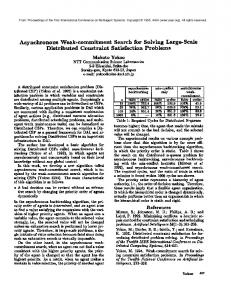
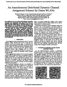
Simulation results are presented in this section to verify the performance of the proposed SDF relay strategy in an asynchronous wireless network. The doubly-selective fading follows the typical urban (TU) power delay profile. It’s assumed that all the nodes have the same transmission power, E, and the same noise variance, σ 2 . The wireless network consists of one source node, one destination node, and two relay nodes. Fig. 2 shows the performance of the wireless network under different values of normalized Doppler spread, fd T0 . The modulation scheme is 16QAM. The results labeled with DF are obtained by forwarding hard decoded information at the output of BDFE at the relay nodes. It can be seen from the figure that the SDF relay strategy always outperforms its DF counterpart. The performance gain is mainly due to the extra reliability information carried by the soft information. As expected, systems with higher fd T0 have better performance at high signal-to-noise ratio (SNR) due to the larger Doppler diversity introduced by time-selective fading. This result demonstrates that the BDFE receiver can achieve Doppler diversity and ICI suppression simultaneously. Fig. 3 compares the performance of asynchronous and synchronous wireless networks under various modulation formats. In the asynchronous case, it’s assumed that there is a clock difference of 0.5Ts between the two relay nodes. The employment of distributed OFDM removes the effects of node asynchronism. Therefore, systems with synchronous relay nodes have the same performance as the asynchronous system. In addition, the proposed SDF method always outperforms the DF method under all system configurations.
[3] T. Wang, A. Cano, G. B. Giannakis, and J. N. Laneman, “Highperformance cooperative demodulation with decode-and-forward relays,” IEEE Trans. Commun., vol. 55, pp. 1427 - 1438, July 2007. [4] X. Bao and J. Li, “Efficient message relaying for wireless user cooperation: decode-amplify-forward (DAF) and hybrid DAF and codedcooperation,” IEEE Trans. Wireless Commun., vol. 6, pp. 3975 - 3984, Nov. 2007. [5] T. Bui and J. Yuan, “A decode and forward cooperation scheme with soft relaying in wireless communication,” in Proc. IEEE Sig. Proc. Adv. Wireless Commun. SPAWC’07, pp. 1 - 5, June 2007. [6] Y. Mei, Y. Hua, A. Swami, and B. Daneshrad, “Combating synchronization errors in cooperative relays,” in Proc. IEEE Intern. Conf. Acoustics Speech Signal Processsing ICASSP’05, vol. 3, pp. 369 - 372, March 2005. [7] Z. Li and X.-G. Xia, “A simple Alamouti space-time transmission scheme for asynchronous cooperative systems,” IEEE Sig. Proc. Lett., vol. 14, pp. 804 - 807, Nov. 2007. [8] C. Xiao, J. Wu, S.-Y. Leong, Y. R. Zheng, and K. B. Letaief, “A discretetime model for spatio-temporally correlated MIMO WSSUS multipath Channels,” IEEE Trans. Wireless Commun., vol. 3, pp.1678 - 1688, Sept. 2004. [9] J. Wu and C. Xiao, “Optimal diversity combining with linear channel estimation in Ricean fading,” accepted for publication by IEEE Trans. Commun., 2008. 16QAM
0
10
DF, fdT0=0 SDF, fdT0=0 DF, f T =1 d 0
SDF, fdT0=1 −1
10
BER
IV. S IMULATION R ESULTS
−2
10
−3
10
−4
10
V. C ONCLUSIONS
0
5
10
15
20
25
E/σ2
Fig. 2.
Comparison of DF and SDF under various values of fd T0 .
0
10
16QAM
−1
10
−2
10 BER
A new soft-decode-and-forward relay strategy was proposed for asynchronous wireless networks operating in a doublyselective fading environment. Soft information at relay nodes is evaluated by passing the received signals through a nonlinear BDFE filter. The obtained soft information carries both original data and corresponding reliability information, and it preserves the correlation between the signals delivered by the relay nodes and the source node. Distributed OFDM was employed to cope with nodes asynchronism and doublyselective fading. The adoption of soft decoding at the relay nodes removes the assumption of perfect relay detection as required by other distributed OFDM systems. The new SDF relay strategy can generate soft information that is able to flexibly adapt to the dynamic signal qualities at the relay nodes.
QPSK −3
10
−4
DF (synchronous)
10
SDF (synchronous) DF (asynchronous)
R EFERENCES
SDF (asynchronous)
[1] T. Cover, and A. A. Elgamal, “Capacity theorems for the relay channel,” IEEE Trans. Inf. Theory, vol. 25, pp. 572 - 584, Sept. 1979. [2] O. Canpolat, M. Uysal, M. M. Fareed, “Analysis and design of distributed space-time trellis codes With amplify-and-forward relaying,” IEEE Trans. Veh. Technol., vol. 56, pp. 1649 - 1660, July 2007. space time trellis, AF, aymptoic (infinit relay), perfect synchronization
0
5
10
15
20
25
2
E/σ
Fig. 3. Comparison of DF and SDF in synchronous and asynchronous networks.
978-1-4244-4148-8/09/$25.00 ©2009 This full text paper was peer reviewed at the direction of IEEE Communications Society subject matter experts for publication in the IEEE "GLOBECOM" 2009 proceedings.