Nigerian Journal of Technology, Vol. 22, No. 1, March 2003
Bakpo
15
SOFTWARE DESIGN MODELLING WITH FUNCTIONAL PETRI NETS F.S. Bakpo Department of Computer Science, University of Nigeria, Nsukka
[email protected] ABSTRACT Petri Nets use two basic primitives: events and conditions to view or model a system. Events are the actions that take place in the system. The occurrence of events is controlled by the "state" of the system, which can be described as a set of conditions. An immediate application of such a model is in the control structures of conventional programming languages. Control structures are the backbone of every programming language. In this paper, an equivalent functional Petri Net (FPN) model is developed for each of the three constructs of structured programs and a FPN Software prototype proposed for the conventional programming construct: if-then-else statement. The motivating idea is essentially to show that FPNs could be used as an alternative approach for program design. 1. INTRODUCTION The concept of Petri Nets has its origin in Carl Adam Petri's dissertation “Kommunikation mit Automaton”, submitted in 1962 to the Faculty of Mathematics and Physics at the Technische Universitat Darmstadt, Germany [9]. Since then the use and study of Petri nets have increased considerably. For a review of the history of Petri nets and an extensive bibliography the reader is referred to [1, 6, 8, 12, 14]. A Petri net has been described in [2] and [3] as a convenient graphical and mathematical modeling tool allowing for easy representation of concurrency, synchronization and conflict among parts of the modeled system. Other areas of immediate applications include distributed data base system, communication protocols, system programs, computer hardware systems, workflow management and performance study of complex processes [1,10,13,14]. A Petri Net has been defined as a quadruple N = (P, T, F, W) where: P is the set of places
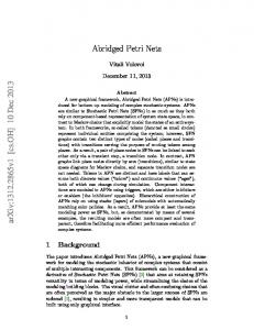
(graphically represented as circles) with /P/ = n and P. T is the set of transitions (graphically represented as bars\) with /T/ = m and T,TP = .F (P x T) U (T x P) the flow relation of N. W: F N\ {0} attaches a weight to each arc of the net. Figure 1 depicts an example of a Petri net.
It consists of places (circle), transitions (bar) and directed arcs (flow relations) that
Nigerian Journal of Technology, Vol. 22, No. 1, March 2003
Bakpo
16
connect them. Input arcs connect places with transitions, while output arcs start at a transition and end at a place. A place may contain zero or more marking also called weights or tokens. The current state of a modeled system (the marking) is given by the number (and type) of tokens in each place. Transitions are active components and are used in modeling activities (events) which can occur (the transition fires), thus changing the state of the system (the marking of the Petri net). Transitions may
fire only if they are enabled, which means that all the preconditions for the activity (or events) must be fulfilled. Usually, this happens if here are enough tokens available in the input places. When the transition fires, it removes tokens from its input places and adds some at its entire output place. The number of tokens removed/added depends on the cardinality of each arc. In figure 1, places PI, P2 initially hold one marker each, as follows:
The Petri net in figure 1 may be used to model a program, which compares two (sorted) arrays to determine whether they have the same set of elements. As we all know, one of the capabilities that make computers so useful is their ability to make conditional decisions and to execute different instructions based on the values of data being processed. These decisions are .usually built into language control structures and constitute the program logic. Consequently, Petri nets could be used to model and verify the correct behavior of programs.
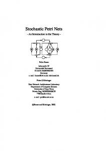
methods and techniques of software design. One of such techniques is called structured programming. Structured programming refers to the process of designing algorithms in terms of "structured flowcharts". A flowchart is a directed network having three kinds of verticesfunction vertex, predicate vertex and collecting vertex, which are illustrated in figure 2.
2. OVERVIEW OF PROGRAMMING LANGUAGE CONSTRUCTS In developing computer software, computer scientists and engineers study various
Nigerian Journal of Technology, Vol. 22, No. 1, March 2003
A function vertex is used to represent a function F: X ® y. A predicate vertex is used to represent a function (or predicate) P: X {T, F} that is, a Boolean expression, which passes control along one of two branches. A collecting vertex represents the passage of control from either of the two incoming branches to one outgoing branch. A structured flowchart is therefore a flowchart, which is composed of the three primitive flowcharts shown in figure 3.
(a) do SI; S2 od (b) if B then Sl else S2 fi (c) While B do SI od These primitives are known respectively as Sequence, Selection, and Iteration. Virtually all computer programs that are of some practical interest can be represented by flowcharts. It has also been shown by [4] and [10] that any flowchart can in turn be represented by a structured flowchart. An immediate corollary of this result is that the three primitive flowcharts of figure 3 are sufficient to design any algorithm. The flowcharts of figure 3(a) - (c) are referred
Bakpo
17
to as program control structures. The purpose of a structured flowchart is twofold: (i) To enable the programmer to arrive at an acceptable structure for a program by identifying its component modules and their mutual interaction. This is aptly the main purpose. (ii)To generate semi-automatically the program algorithm by implementing in Pseudocode the control structures indicated in the structured flowchart. This is a by- product Software designers must limit the number of features included in a program so that it will not require more memory than the system for which it is designed. 3 THE CONCEPTS OF FUNCTIONAL PETRI NETS AND LANGUAGE CONSTRUCTS A Complex Process (CP) is an ordered 5 tuple = (S, K, D, Mo, I), where S Functional Petri Net (FPN); K - set of constructions in the CP; D -set of labels associated with entry points; Mo -initial states or markings of the CP; I - system's Interpreter [2,7,11]. Definition1 A functional Petri net (FPN) has been defined in [2] as a 5 – tuple S = (P,T,F, μ0, C),where P =PO UPv UPC U Pe places designated respectively for operators, variables ( operands), constants and conditions; Po= P of UPoe UPoi - that is, an operator place may in turn be functional, logical or iteration; T = Ti, U To - input and output transitions; F - incidence matrix or function of the net; μ0 -initial marking (start) of the net. C = {C1}, i = 1, n - a set of colors, where C1 -is the set of marking colors in the ith place (Pi) and n - is the number of places in the net. Consequently,
Nigerian Journal of Technology, Vol. 22, No. 1, March 2003
a FPN has been introduced as an extension of the classical Petri net obtained as a union of E-net [2,7] and colors Petri nets [5]. A
FPN conditions i. F(p) ≤2p{Pv U Pc}; ii. F(P) ≤1PP; iii.
F(t) ≤1tTi;
iv.
F(P) ≤ 1PPo;
v.
F(t) 1tT1;
vi.
F(t) tTo;
Bakpo
18
FPN must satisfy the following conditions
Explanations Input places into a constituent module of FPN must be equal to or less than 2 The output place must be less or equal to.1 The output from transition must be less or equal to 1 The output into elementary constructs F(P)must be equal or less than 1 The input to transition must be greater or equal to 1. The output from elementary constructs F(t) must be greater or equal to 1.
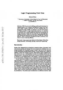
4. MAPPING SOFTWARE DESIGN CONCEPTS ONTO FUNCTIONAL PETRI NETS Definition 2 In a CP, construction is defined as K = {Ke, Kc,}, where Ke elementary (or primitive) constructs and Kc - constituent modules (or subgraphs) of the net. Thus, a CP consists of modules, where each module in turn consists of elementary constructs. This is similar in concepts to the Top down design methodology. There are three types of elementary constructs in FPN, depending on the type of operation. Thus, we have Ke = {Kef, Kel, Kei,}, where Kef KeI, Kei, - are elementary functional, logical and iteration constructs, respectively. Figure 4 shows these three elementary constructs. A functional construct may have n+ I input variables (operands) of which one may be constant and m output variables. The net functions
by processing the variables in sequence.
That is, Pvi is processed to yield Pv(n+l) before Pv2 is processed. The syntax is: . [] (, []) (,[]), where N is a Petri net label.
Nigerian Journal of Technology, Vol. 22, No. 1, March 2003
Bakpo
19
The iteration construct is adirect consequence of the logical construct. Here, if the condition stated in the logical construct is true, the subnet on the left-hand part will fire, otherwise, execution follows the right- hand part. Similarly, a composite module Kc = {Kcf; KcI}, where Kcf - is functional construct; and Kc1, -is a logical construct.
The syntax of a logical construct is as follows: = COND. (, ) (T = , E = ) =T. ( ... ) ( ... ); = E. (, ... ) ( ... ); Notice in figure 4(b) that the logical construct is the key to determining which way the flow will go. It consists of not more than two input variables (places) at a time and two possible outcomes of the logical - true or false. The execution of a statement decreases values of variables corresponding to its input places by 1 (provided they are all positive) and increases values of variables corresponding to its output places by 1, in one multiple assignment.
Definition 3 A composite module Kc, = (Pc,
Nigerian Journal of Technology, Vol. 22, No. 1, March 2003
Tc, Fc μoc Cc) is a sub graph of FPN in which each place p Pc, Fc – denotes incidence function, μoc - initial marking of the net for p Pc, In a FPN, places are designated as input and output whereas transitions are also designated as input and output. These definitions are as follows: (i) An input transition of a composite module or sub graph may be defined as: Tic= {t\t Tib p {p/P F (t)} p Pb}; where Tib is subsets of input transitions in the composite module and Pb - a set of places in the composite module; (ii) An output transition of a composite module is also defined as: Toc= {t\ t Tob, p Pn, p {p \ t F (p) }}. (iii) An output (variable) place in the composite module may be defined as Pvc= {p\ P Pb}. Figure 5 illustrates a FPN model of the conventional programming language construct: If A = B then FN2 else FN3. An if-then-else block permits one of two different groups of executable statements to be executed, depending on the outcome of a logical test. If the logical expression is true, then the first group of executable statements FN2 will be executed. Otherwise, the second group of executed statements FN3 will be executed. Figure 5 (a) depicts the model of such computation using the three primitive constructs Definition 4 A set of labels D associated with entry points D = {dov; dbv, dlv}, where dov, dbv and dlv, are labels of operand, Boolean, and linked variables, respectively. Labels of operand variables are obtained as output of a functional construct while labels of Boolean variables are obtained as output of logical construct where decisions are taken based on the logical values of
Bakpo
20
True or False. Labels of linked variables are obtained during compilation and refer to the various modules that will be linked together before execution. Definition 5 In a CP, the system's interpreter is defined as: I: μo X μ(Pv) = Mo X D, where Mo- denotes initial marking, and D - set of labels. The system's interpreter is discussed in more detail in [2].
5.SOFTWARE PROTOTYPE USING FUNCTIONAL PETRI NETS. The classical Petri net allows for the modeling of states, events, conditions, synchronization, parallelism, choice, and iteration. However, Petri nets describing real processes tend to be complex and extremely large. Moreover, the classical Petri net does not allow for the modeling of data and time. To solve these problems in [4] and [14] three different extensions of the basic Petri net were proposed. These are: (1) the extension with color to model data; (2) the extension with time and (3) the extension with hierarchy to structure large models. In this section, the extension with hierarchy is employed. A hierarchy or elementary construct or subnet is an aggregate of a number of places, transitions, and subsystems. If the dotted portion in figure 5 (a) is replaced by the logical construct (subnet) of FPN, then it is possible to modify figure 5 (a) without changing its hierarchical structure. The equivalent model is depicted in figure 5 (b).
Nigerian Journal of Technology, Vol. 22, No. 1, March 2003
Bakpo
21
OUT (, ) (,[]); END/ * Absence of token or variables */ Where ddv denotes FPN labels.
Figure 5 (b) shows the conventional IF THEN- ELSE programming statement composed using subnets of FPN. A Petri net extended with these properties may be called a high-level Petri Net. The corresponding software prototype follows: START/* Presence of tokens or variables */ INP (, ) IF (, ) (T , E = ); T. (, ,, ... ,) (