Cooling load estimation through computer application sounds reasonable to replace tedious and time consuming manual methods. To achieve this computer.
IOSR Journal of Mechanical and Civil Engineering (IOSR-JMCE) ISSN: 2278-1684Volume 3, Issue 6 (Nov. - Dec. 2012), PP 01-06 www.iosrjournals.org
Software Development for Cooling Load Estimation by CLTD Method Tousif Ahmed Department of Mechanical Engineering, Bangladesh University of Engineering and Technology, Bangladesh
Abstract : Traditionally, load estimating for air conditioning systems is done either by manual calculation or judgmental estimation based on experience of the air conditioning practitioner. While manual calculation is laborious, estimate based on judgment is liable to error due to gigantic, complex and dynamic nature of present day architectural designs. Load estimating through computer automation is likely to make a positive impact in the dynamic nature of air conditioning applications. This study develops computer software in C# .NET (C Sharp dot NET) to handle simple and typical load estimate for air conditioning in developing country (i.e. Bangladesh). Though this study deals with simplified model of a room, this software can be improved to calculate intricate and dynamic nature of load with a very little effort. Currently, there are several commercial packages available in the market not only for the cooling load calculations, but also for other applications of heating, ventilating, and air-conditioning (HVAC) systems. But, commercial softwares for cooling load estimation and HVAC design are very costly for the peoples of developing countries like Bangladesh. The main objective of this development is to provide a free and easy way to estimate cooling load for air-conditioning. Keywords -Cooling load, CLTD method, HVAC, C# dot NET, CLF, Trace700.
I.
INTRODUCTION
Cooling load estimation is the first step to controlled air-conditioning. Air-conditioning is utilised to supply a controlled atmosphere to public buildings such as offices, halls, homes, and industries for the comfort of human being or for the proper performance of some industrial processes. Full air-conditioning implies that the purity, movement, temperature and relative humidity of the air be controlled within the limits imposed by the design specification. For any air conditioning system to perform satisfactorily, equipment of the proper capacity must be selected based on the instantaneous peak load requirements. The type of control used is dictated by the conditions to be maintained during peak and partial load. Undersized equipment will not provide the required conditions while a greatly oversized one will lead to operating problems such as “hunting”. Load estimating in air-conditioning system design has been carried out manually in many quarters in developing country such as Bangladesh. A lot of time and energy are wasted when estimating the cooling loads in complex and intricate buildings of modern time. Cooling load estimation through computer application sounds reasonable to replace tedious and time consuming manual methods. To achieve this computer automation, software is developed using “C# dot NET” programming language tool. “C# dot NET” is used in this work because of its simplicity and easily understandable by professionals. Besides, it is a versatile tool that has ability to handle large and complex problem of this kind.
II.
COOLING LOAD CALCULATION TECHNIQUES
For a thorough calculation of the zones and whole-building loads, one of the following three methods should be employed: A. Transfer Function Method (TFM): This is the most complex of the methods proposed by ASHRAE and requires the use of a computer program or advanced spreadsheet. B. Cooling Load Temperature Differential/Cooling Load Factors (CLTD/CLF): This method is derived from the TFM method and uses tabulated data to simplify the calculation process. The method can be fairly easily transferred into simple spreadsheet programs but has some limitations due to the use of tabulated data. C. Total Equivalent Temperature Differential/Time-Averaging (TETD/TA): This was the preferred method for hand or simple spreadsheet calculation before the introduction of the CLTD/CLF method. For strictly manual cooling load calculation method, the most practical to use is the CLTD/CLF method as described in the 1997 ASHRAE Fundamentals. This method, although not optimum, will yield the most conservative results based on peak load values to be used in sizing equipment. It should be noted that the results obtained from using the CLTD/CLF method depend largely on the characteristics of the space being considered and how they vary from the model used to generate the CLTD/CLF data shown on the various tables. www.iosrjournals.org
1 | Page
Software Development for Cooling Load Estimation by CLTD Method Engineering judgment is required in the interpretation of the custom tables and applying appropriate correction factors. When this method is used in conjunction with custom tables generated by appropriate computer software (McQuiston and Spitler 1992) and for buildings where external shading is not significant, it can be expected to produce results very close to those produced by the TFM. When the printed tables are used, some additional error is introduced. In many cases, the accuracy should be sufficient.
III.
CONSIDERATIONS AND ASSUMPTIONS
Design cooling load takes into account all the loads experienced by a building under a specific set of assumed conditions. The assumptions behind design cooling load are as follows: Weather conditions are selected from a long-term statistical database. The conditions will not necessary represent any actual year, but are representative of the location of the building. ASHRAE has tabulated such data. The solar loads on the building are assumed to be those that would occur on a clear day in the month chosen for the calculations. All building equipment and appliances are considered to be operating at a reasonably representative capacity. Latent as well as sensible loads are considered. The latent heat gain is assumed to become cooling load instantly, whereas the sensible heat gain is partially delayed depending on the characteristics of the conditioned space. According to the ASHRAE regulations, the sensible heat gain from people is assumed 30% convection (instant cooling load) and 70% radiative (delayed portion). The ventilation rates are either assumed on air changes or based on maximum occupancy expected. Design dry blub of 2.5% in summer and 97.5% in winter for Chittagong city is considered. 2.5% means that temperature exceeds the value (330C) only 2.5% of all the hours in summer months. Windows are externally shaded.
IV.
METHODOLOGY
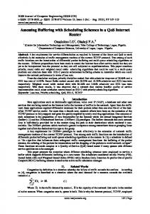
The whole software was developed in the Microsoft Visual Studio, a popular C# dot net IDE. There were four tabs in total to give input of different parameters associated with roof and wall constructions, indoor and outdoor conditions, air ventilation, equipments and occupants. Figure 1 shows the GUI (Graphical User Interface) of the developed software.
Fig. 1 GUI (graphical User Interface) of the software The CLTD/SCL/CLF method is a one-step, hand calculation procedure, based on the transfer function method (TFM). It may be used to approximate the cooling load corresponding to the first three modes of heat gain (conductive heat gain through surfaces such as windows, walls, and roofs; solar heat gain through fenestrations; and internal heat gain from lights, people, and equipment) and the cooling load from infiltration and ventilation. www.iosrjournals.org
2 | Page
Software Development for Cooling Load Estimation by CLTD Method The sources of the space cooling load, forms of equations to use in the calculations, appropriate references, are given below: A.
External Cooling Load Estimation Roofs, walls, and conduction through glass qsunlit = UA(CLTDC) [1] CLTDC = (CLTD + LM) * K + (25.5-tr) + (to,av-29.4) [2]
U = design heat transfer coefficient for roof or wall LM= latitude and month factor A = area of roof, wall, or glass, calculated from building plans K= wall colour adjustment factor tr = inside design temperature (constant) in conditioned space to,av = to,max-(daily range/2) CLTDC = corrected cooling load temperature difference, roof, wall, or glass
Solar load through glass qrad = A(SC)(SHGF)(CLF) [2]
SC = shading coefficient SHGF = solar heat gain factor for externally shaded windows CLF = cooling load factor
Cooling load from partition walls and windows qpartition =UA(to – tr) [2]
U = design heat transfer coefficient for partition walls and windows A = area of partition walls and windows calculated from building Plans to = temperature in adjacent space tr = inside design temperature (constant) in conditioned space B.
Internal Cooling Load Estimation People qs = N(Sensible heat gain)CLF [1] ql = N(Latent heat gain) [1]
N = number of people in space, from best available source. CLF = cooling load factor, by hour of occupancy Lights qlight = (N)(W)(CLF)(BF) [2] N = number of lights in space. BF = Ballast factor, 1.0 for incandescent bulb and 1.2 for fluorescent light W = watts input from electrical plans or lighting fixture data CLF = cooling load factor, by hour of occupancy, assumed 0.85
Appliances and equipments qe = (N)(W)(CLF) [1]
N = number of appliances and equipments in space. W = watts input from electrical plans www.iosrjournals.org
3 | Page
Software Development for Cooling Load Estimation by CLTD Method CLF = cooling load factor, by hour of occupancy and room furnishings; 1.0 for 24 hours of operation C.
Ventilation and Infiltration Air Load Estimation qsensible = 1200 Q (to − ti) [2] qlatent = 3000 x103 Q (ωo − ωi) [2] qair total=qsensible +qlatent
Q = room volume x ACH (air change per hour), m 3/s to, ti = outside, inside air temperature, °C ωo, ωi = outside, inside air humidity ratio, kg (water)/kg (dry air) To compute cooling load of different components of the defined room different functions were defined which are listed on table I. TABLE I DEFINED FUNCTIONS and THEIR ACTIONS Parameters Functions Defined Actions Thermal conductivity of private double roof_u() Reads roof input data and roof properties of layers from database and computes roof thermal conductivity Thermal conductivity of private double wall_u() Reads wall input data and wall properties of layers from database and computes wall thermal conductivity qpartition private double Q_partition() Computes cooling load for partition components qsunlit private double Q_sunlit() Computes cooling load for sunlit components qair total private double Q_air() Computes cooling load for air infiltration qs, ql private double Q_occupants() Computes cooling load for air infiltration qe, qlight private double Computes cooling load for Q_equipments() lights and equipments After all the parameters are given, the software computes cooling load according to the following flowchart: Start
Input Load parameters
Roof and wall (sunlit or partition)?
Window and doors?
Roof and wall load
Window and door load
Air infiltration?
Air change load (latent and sensible)
Any modification ?
Equipments?
Equipments load
Sum all loads to estimate cooling load
Occupants?
Occupants load (latent and sensible)
Show result Stop
Fig. 2 Operational flowchart of the software www.iosrjournals.org
4 | Page
Software Development for Cooling Load Estimation by CLTD Method V.
CASE STUDY and RESULTS
To test the software (estimate cooling load) a model room with following characteristics was assumed: Day 12TH April, time 3PM. Outdoor temperature 300C and temperature other side of the partition wall is 330C. Room is to be maintained at 25oC and 50% relative humidity. Room dimensions: length 10m, breadth 8m, height 3m Roof: 100 mm light weight concrete without suspended ceiling. Wall: Group C type 101.6 mm Face Brick + Air Space + 101.6 mm Face brick East wall and West wall as sunlit wall and others as partition wall. Windows = Sunlit, 25% of West wall area, 13 mm clear glass with U = 3.0 W/m 2C Light = 25W/m2 of floor area ACH (Air Change/hour) = 1/hour Office room, accommodating 10 people using 5 Computers Estimated cooling load of the software was 10.193 kW or 2.9 ton. This result is very close to that of “TRACE 700”, a professional cooling load estimation and HVAC design software. “TRACE 700” gives 9.96 kW or 2.83 ton as required cooling load. Figure 2 shows cooling load required for the given problem in two different seasons (April and January). April is the hottest and January is the coldest season in Bangladesh. From the figure 2, it is evident that cooling load curve maintain same pattern with months and in hot seasons more cooling load is required than cold seasons. Moreover, maximum cooling load requires somewhere between 4.00PM to 5.00 PM in a day. 12
Cooling Load (kW)
10 8 6 4
January
2
April
0 1
6
11 Hours 16 21 Fig. 2 Required cooling load curve developed by the software A little deviation (2.34% error) from “TRACE 700” occurs due to some assumptions and design considerations made. As custom thickness of walls and roofs were not provided, some errors happened due to thickness mismatch. Moreover, cooling load factor (CLF) for all lights was assumed 0.85 for simplicity and easy database construction which was also a source of deviation from “TRACE 700”.
VI.
Future works and Improvements
The factors that must be critically looked into during load estimation process include orientation of building (location), space used, dimensions, column and beams, construction materials, surrounding conditions, windows, doors, people, lighting, ventilation, thermal storage and floor. But, for simplicity some values were assumed rather than read out accurate values from the database. CLF for lights were assumed 0.85. Following improvements can be made: In future CLF values for lights can be evaluated from CLF tables of ASHRAE fundamentals handbook by providing provision for selecting room furnishing and equipment operation conditions. Only few predefined walls are available in this software. For ease of use custom input methods can be introduced. Vast different wall construction materials and their properties can be included in the database. Due to data unavailability only Chittagong city’s design data were used for the development of the software. As Bangladesh is a small country, design data of Chittagong gives pretty good results. But all cities’ design data can be included for more precise results on the basis of data availability.
www.iosrjournals.org
5 | Page
Software Development for Cooling Load Estimation by CLTD Method VII.
CONCLUSIONS
The study has developed a system framework that estimate cooling loads for air-conditioning system for simple residential and non-residential buildings. Although the features of this software may be limited when compared with those commercial packages in the market, it does provide an effective and user-friendly way of introducing a residential cooling load calculation program to users. If given more time and resources, the present program can be extended to include commercial buildings and completed with the heating load calculation. In addition, the dimensions and layout of the building can be made variable. The sizing of air-conditioning equipment for the building and the design of air distribution system can also be incorporated in this program. Moreover, this software can be used as a reference for educational purposes.
REFERENCE [1] [2] [3] [4]
ASHRAE, (1997). ASHRAE Fundamentals Handbook, American Society of Heating, Air-Conditioning and Refrigeration Publishing Service. ASHRAE, (1989). ASHRAE Fundamentals Handbook, American Society of Heating, Air-Conditioning and Refrigeration Publishing Service. B. Kareem, “Load Estimating for Air Conditioning using Computer Software Approach,” International Journal of The Computer, the Internet and Management Vol.16. N.o.2 (May-August, 2008) pp 35-43 Shan K. Wang, Handbook of Air Conditioning and Refrigeration, 2nd ed., McGraw-Hill, 2000.
www.iosrjournals.org
6 | Page