commercially available acoustic modems [9,10] to more affordable dedicated integrated ..... The second type of filter is FFT, which is suitable for micro-server or ...
Software-Driven Sensor Networks for Short-Range Shallow Water Applications
Raja Jurdak ∗ , School of Computer Science and Informatics, University College Dublin, Ireland.
Pierre Baldi, and Cristina Videira Lopes School of Information and Computer Sciences, University of California, Irvine, USA {pfbaldi, lopes} @ics.uci.edu
Abstract Most existing underwater networks target deep and long range oceanic environments, which has led to the design of power hungry and expensive underwater communication hardware. Because of prohibitive monetary and energy cost of currently overengineered communication hardware, dense deployments of shallow water sensor networks remain an elusive goal. To enable dense shallow water networks, we propose a network architecture that builds on the success of terrestrial sensor motes and that relies on the coupling of software modems and widely available speakers and microphones in sensor motes to establish acoustic communication links. In this paper, we analytically and empirically explore the potential of this acoustic communication system for the underwater environment. Our experimental approach first profiles the hardware in water after waterproofing the components with elastic membranes. The medium profiling results expose the favorable frequencies of operation for the hardware, enabling us to design a software FSK modem. Subsequently, our experiments evaluate the data transfer capability of the underwater channel with 8-frequency FSK software modems. The experiments within a 17x8 m controlled underwater environment yield an error-free channel capacity of 24 bps, and they also demonstrate that the system supports date rates between 6 and 48 bps with adaptive fidelity.
∗ Corresponding author. Preprint submitted to Elsevier Science
13 May 2008
1
Introduction
Water is a crucial resource for most life on earth, covering more than 70% of our planet. Sustainable use and exploitation of our water resources requires a deep understanding of both oceanic and inland aquatic environments through long-term monitoring of these environments. Existing aquatic monitoring platforms have attempted to capture information at high temporal scale (e.g. surface buoys with suspended probes in the water, satellites that observe large geographic regions) or high spatial scale (e.g. research vessels that survey sea floors) from the oceanic environment. Monitoring aquatic environments at both high temporal and spatial scales remains an elusive goal despite its strategic significance to the social and economic development of the global population.
An enabling technology for granular monitoring of aquatic environments is wireless sensor networks, which has been successful in many terrestrial applications. A dense deployment of in-situ sensor nodes that communicate wirelessly in the water can meet the scale requirements of aquatic monitoring, as the sensor nodes are relatively cheap (ranging from 10 to 250 US dollars in price depending on purchase volume) compared to conventional platforms, making it cost-feasible to deploy a large number of nodes in a physical area. Because the nodes reside in the aquatic environment, they can supply data at any temporal scale required by the network user. Adapting sensor nodes for wireless underwater communication requires the addition of hardware for acoustic modulation and communication. While the cost of sensor modules themselves is low, the cost of add-on hardware for acoustic communication, for modulation and demodulation, and for protecting and waterproofing the components is prohibitive, typically running into the thousands of dollars.
Most of the existing work on wireless underwater networking targets oceanic applications, where the communication range and depth are typically in the order of hundreds to thousands of meters, and the data transfer rates go up to few Kbits per second. Design strategies for wireless underwater communication in the oceanic environment must also consider harsh conditions and peculiar characteristics of the underwater channel that distinguish it from the aerial channel [1]. First, the underwater channel has severely limited bandwidth that is highly dependent on communication range, which requires bandwidth-efficient modulation and data compression techniques. Another unique characteristic of the underwater channel is the time-varying multi-path effects, where inter-symbol interference can span several data symbols. The fading and outage behavior of the underwater channel is also not yet understood. This requires dynamic protocols that rely on cross-layer optimization to adapt to unpredictable channel variations. Finally, the speed of sound in water, which is 1500 2
m/s, is significantly lower than the speed of electro-magnetic signals in air. The relatively slow signal speed in water causes severe doppler distortion and very long propagation delays. This emphasizes the importance of synchronization mechanisms and throughput efficiency of protocols. The numerous constraints for wireless underwater communications in medium to long range oceanic applications has led companies and researchers to highly engineer specialized hardware for modulating, transmitting, receiving and demodulating acoustic signals. The specialized modulation hardware ranges from expensive commercially available acoustic modems [9, 10] to more affordable dedicated integrated circuits [6] and dedicated DSP boards [11–13]. The communication hardware ranges from specialized underwater acoustic transducers and hydrophones [7] to generic speakers and microphones [6]. The use of specialized hardware for establishing acoustic communications underwater typically increases the network cost, the design time spent in interfacing node hardware components, and the size and weight of individual network nodes. While using specialized hardware is a necessity for oceanic applications to establish communication links, it represents an overkill for short range shallow water applications, such as the water quality monitoring of lakes, bays, rivers, estuaries, and reservoirs. Water quality monitoring in a river [2] exemplifies an application that requires monitoring at a high spatial granularity, which is synonymous with short inter-node distances in sensor networks, in order to capture the small scale variations in contamination and to identify pollution sources and causes. Nodes located at close proximity to each other only require short-range wireless communication in the water. Despite the availability of underwater communication hardware, short-range shallow water monitoring applications have not adopted existing technologies specifically because of their prohibitive cost and over-engineering for this class of applications. Shallow water networks refer to depths ranging from 0 m to 50 m, where sound propagation is mostly horizontal except for surface and bottom reflections [3]. Section 5 considers the impact of applying our architecture to deep water networks. In the past, most underwater deployment efforts have focused on hardware acoustic modulation because low processing speeds did not allow the modulation of acoustic signals in software. Software modulation and demodulation [14] is an alternative approach which overcomes most of the drawbacks of hardware modems. Recent advances in miniaturization and circuit integration have yielded smaller and more powerful processors that are capable of efficiently running acoustic modulation and demodulation software. Software modulation also provides a higher level of flexibility for on-the-fly tuning of modulation parameters to suit different environments. The transmission and reception of the software modulated acoustic signal can also avoid using specialized hardware through generic speakers and microphones. 3
Eliminating the need for specialized hardware for acoustic communication greatly reduces the cost of network nodes, which facilitates the dense deployment of mote-class nodes to form underwater sensor networks. Within this context, this article proposes software-driven underwater acoustic sensor networks for dense shallow water quality monitoring in rivers, bays, estuaries, and lakes. The network consists of affordable off-the-shelf sensor modules (motes) that use software modems and generic hardware to communicate acoustically and send the data towards the base station through multi-hop communication. The motes are placed into elastic latex membranes that waterproof the hardware while maintaining acoustic coupling with the water channel. In addition to being cost-feasible and satisfying the temporal and spatial scale requirements, sensor motes, which are originally designed for terrestrial applications, combine processing and storage capabilities that provide an intelligent platform for network self-configuration and self-management. Finally, the speakers on board the mote platform have low output power, which is favorable for both network longevity and for minimizing interference with aquatic ecosystems. Software-driven underwater sensor networks involve the design and development of the acoustic communication links, communication protocols, and application behavior. This paper investigates the design and development of reliable acoustic communication links for realizing software-driven underwater sensor networks. In particular, the paper first profiles through empirical experiments the unique channel of the proposed software-driven underwater sensor networks that includes the speaker, the microphone, the latex membranes, and the water. Based on the underwater profiling results, we derive the theoretical error-free transfer rate of each hardware set. To validate the transfer rate projections, our second set of experiments evaluates the data transfer capability of the underwater channel with 8-frequency FSK software modems coupled with the mote’s acoustic hardware. The novel contributions of this paper are: (1) Proposal of a cost-effective low-power sensor network architecture for short-range shallow water applications, based on the coupling of software modems and off-the-shelf motes equipped with generic acoustic hardware. (2) Validation of the feasibility of the wireless communication links driving this architecture by empirically profiling the underwater channel to determine the frequencies with the highest signal-to-noise (SN R) for this channel (3) Proposal and empirical evaluation of FSK software modems for acoustic data modulation, based on the best frequencies identified in (2), to determine achievable bit rates and symbol error rates as a function 4
of communication range. The remainder of this paper is organized as follows. Section 2 discusses the related work on underwater network architecture and on both hardware and software acoustic modems. Section 3 presents the network architecture and its main components, with a focus on the physical layer functionality, underwater acoustic concepts, and implementation issues. Section 4 demonstrates the acoustic communication capability of our acoustic communication system through profiling experiments for Tmote hardware in the underwater medium. The resulting medium profile results enables the design of a simple FSK modem. We use the modem to evaluate the data transfer characteristics of our acoustic underwater communication system. Section 5 discusses the wider applicability of the communication system for underwater sensor networks and concludes the paper.
2
Related Work
This section first reviews existing architecture for underwater networks. The latter part of the section discusses acoustic modulation, both in hardware and in software, as an enabler of wireless underwater communication.
2.1
Underwater Network Architectures
Most underwater network proposals rely on wireless acoustic communication between a set of underwater nodes, which eventually relay information to a node at the surface. Akyildiz et al. [5] define both 2-dimensional and 3-dimensional architectures for underwater networks. The 2-dimensional architecture follows a clustered topology in which each group of underwater nodes that are fixed to the sea floor communicates with more powerful nodes, or clusterheads, in their vicinity. The clusterheads then relay the data to a surface node, which in turns forwards the data through satellite or long range radio links to a central repository. The 3-dimensional architecture considers underwater sensor nodes that are anchored to the sea-floor, thus allowing them to float at different depths depending on currents and tides. Since our paper considers shallow water applications with communication at very short ranges, differences in depth are relatively small so the network adheres to the 2-dimensional architecture. 5
Another recent survey by Cui et al. [4] classifies underwater network architectures according to their deployment duration and the criticality of data they sense, differentiating between two architecture classes: long-term non-critical deployments; and short-term critical deployments. Their article also identifies very short range underwater acoustic modems as a gap in the current state-of the art. Our work coincides with the long-term non-critical monitoring architecture of Cui et al., and in this paper we specifically target the development and investigation of low power acoustic modems for very short range underwater networks. Vasilescu et al. [6] propose another network architecture where autonomous underwater vehicles (AUV) periodically visit the network area to collect data from the in-situ sensors through ultra short wireless acoustic links. Although our work focuses on the adaptation of stationary mote platforms for the underwater environment, the development of acoustic communication links in that operate with a range of about 20m on the motes would enhance Vasilescu’s architecture, reducing the localization and navigation requirements, as well as the duration of the data collection process by the AUV.
2.2
Hardware Modems
Earlier efforts in acoustic communication have focused on using specialized and dedicated hardware for underwater acoustic modulation and demodulation. Acoustic underwater communication is a mature field and there are several commercially available underwater acoustic modems [9, 10]. The commercially available acoustic modems provide data rates ranging from 100 bps to about 40 Kbps, and they have an operating range of up to a few km and an operating depth in the order of thousands of meters. The cost of a single commercial underwater acoustic modem is at least a few thousand US dollars. The prohibitive cost of commercial underwater modems has been an obstacle to the wide deployment of dense underwater networks, until the recent development of research versions of hardware acoustic modems. Researchers at the Woods Hole Oceanographic Institution are developing a Utility Acoustic Modem (UAM) as a completely self-contained, autonomous acoustic modem capable of moderate communication rates with low power consumption [12]. This modem uses a single specialized DSP board with on board memory and batteries. The purpose of developing the UAM is to make a more affordable acoustic modem available for the research community. Researchers at UC, Santa Barbara are also developing a hardware acoustic underwater telemetry modem [11] for ecological research applications, using a DSP board with custom amplifiers, matching networks, and transducers. Their modem is intended for interfacing to nodes in an 6
underwater ad hoc network, and it achieves a 133 bps data rate. Whereas both of the efforts reported in [12] and [11] aim at making underwater acoustic modems cheaper and more accessible by developing specialized affordable hardware, our work aims at driving the cost even lower and at making acoustic underwater communications even more accessible through the development of software acoustic modems that can operate on generic hardware platforms. In a more recent article, Wills et al. [13] propose their design for an inexpensive hardware modem for dense short-range underwater sensor networks. Their work aims at borrowing communication concepts, such as wake-up radio, from terrestrial sensor networks. Although we share the same end goal as Wills et al. (inexpensive acoustic modems for dense short-range wireless networks), our approach differs in its emphasis on modulation through software rather than through specialized hardware.. One of the few attempts to deal with generic microphones and speakers is Vasilescu et al. [6]. These authors propose a network that combines acoustic and optical communications, stationary nodes and AUV’s for monitoring coral reefs and fisheries with ranges in the order of hundreds of meters. The work in [6] uses generic microphones and speakers along with a specialized integrated circuit that generates ASK or FSK modulated sound signal in order to demonstrate the acoustic communication capability underwater. Vasilescu et al. achieve a bit rate in the order of tens of bits per second up to about 10 to 15 meters. Although our work resembles their work in the use of generic microphones and speakers for acoustic communications, it differs in its proposal and implementation of software modems for off-the-shelf mote platforms rather than the use of specialized integrated circuits for communication.
2.3
Software Modems
With the rapid increase in processor speeds, the idea of implementing acoustic modems in software becomes feasible and even attractive due to the low cost processing power. Coupling software acoustic modems with the use of microphones and speakers for transmission and reception can eliminate the need for specialized hardware for acoustic communication, trading off cheap computational power for expensive communication hardware. The cost of software acoustic modems is limited to the development cost, after which the per unit cost is zero. Because of these attractive features, Lopes and Aguiar [14] have investigated using software modems for 7
Interactive Maps
Surface Buoy
Broadband Radio Connection To Internet
Wireless acoustic links
Underwater sensor nodes
data repository
Query and Download tools
Fig. 1. Target network application
aerial acoustic communications in ubiquitous computing applications. Building on their work, software acoustic modems can also eliminate the need for specialized hardware in underwater acoustic communications, thereby encouraging wider deployment of underwater sensor networks. In preliminary experiments, we started profiling the underwater acoustic spectrum and data communications capabilities with software acoustic modems [18]. Our work used waterproofed generic microphones and speakers, connected to laptops on the surface, for sending and receiving software modulated acoustic signals. The achieved bit rates were in the order of tens of bits per second for distances up to 10 meters. Our work here extends our earlier work by coupling software modems with Tmote Invent module hardware. Since the experiments in [18] used microphones and speakers of comparable specifications to the on-board speakers and microphones on the Tmote Invent module, we expect the underwater acoustic communication capability of autonomous Tmote Invents to yield comparable results. Our recent study in [19] present underwater experiments results that confirm the communication capability of software modems on Tmote Invent hardware. In this paper, we build on those results to propose a cost-effective software-driven sensor network architecture for short range shallow water applications.
3
Network Architecture
This section describes the target network architecture, focusing on the physical layer aspects. Figure 1 sheds more light on the target network application. 8
3.1
Network Overview
Software-driven underwater sensor networks will consist of tens to hundreds of motes deployed in a shallow water environment. The motes can communicate acoustically through short-range wireless links, thanks to their on-board speaker and microphone and to software acoustic modems. The motes are placed into elastic latex membranes, which maintain the acoustic coupling of the on-board speaker and microphone with the water while waterproofing them. The modules periodically sample their sensors, collecting physical indicator data from their built-in sensors, such as water temperature or tidal strength, or from add-on sensors, such as salinity or phosphorous levels, which help determine water contamination levels. After sampling their sensors, the nodes send the sensor values to neighboring nodes, which in turn relay the data through multihop links to the nearest collection point. Because each node periodically sends only few 2-byte sensor values, the data transfer rate requirements of the network are low.
The network architecture supports two embodiments of the collection point: (1) an underwater instrumentation station that relays network data to a data repository on shore through a sub-sea fibre optic cable; or (2) a surface station that resides on a buoy and relays network data to the data repository on shore through a long range RF communication link. For both configurations, the logical network topology is a tree, or more generally, a multiple-tree topology.
3.2
3.2.1
Software-Driven Acoustic Communication
System Components
Figure 2 illustrates the main components of the communication system. At the sender side, digital sensor data from the underwater environment first enter the software modulator, resulting in a modulated acoustic signal. The on-board speaker then transmits this signal into the underwater channel. At the receiver, the on-board microphone captures the signal and the resident software performs symbol synchronization through the S 4 [20] block, filtering through FFT or wavelet decomposition, and finally demodulation. 9
Digital data
Modulator
Modulated acoustic signal
Transmitted acoustic signal Speaker
(a) Received signal at microphone
Microphone
S4
Filter (Bandpass or FFT)
Synch
Demdoulator
(b)
Fig. 2. Block diagram for software modem (a) Modulator/Transmitter (b) Demodulator/Receiver
Fig. 3. The Tmote Invent module
3.2.2
Target Platform
For our application, we have selected mote-class computers, which are powerful enough to perform sufficient in-network processing and are affordable enough to enable the deployment of a dense network at reasonable cost. In particular, we have selected the Tmote Invent module (shown in Figure 3) which has an on-board SSM2167 microphone from Analog Devices sensitive to frequencies from 100Hz to 20kHz, and an on-board TPA0233 speaker amplifier from TI with an 8 ohm speaker that has a range of 400Hz to 20kHz. The goal of this work is to exploit the on-board microphone and speaker to establish short range acoustic links among Invent modules. The next subsection reviews the basic concepts of underwater acoustics that driven the design of our software modem. 10
3.3
Underwater Acoustics
3.3.1
The Passive Sonar Equation
The passive sonar equation [16] characterizes the signal to noise ratio (SN R) of an emitted underwater signal at the receiver:
SN R = SL − T L − N L + DI
(1)
where SL is the source level, T L is the underwater transmission loss, N L is the noise level, and DI is the directivity index. All the quantities in Equation 1 are typically in dB re µP a, where the reference value of 1 µP a amounts to 0.67 × 10⁻²² W atts/cm2 [16]. However, we will use the threshold of human hearing at 10−12 W atts/m2 as our reference signal level, to better compare results with our earlier results in [18]. In the rest of this paper, we use the shorthand notation of dB to signify dB re 10−12 , unless otherwise mentioned. For the purpose of this analysis, we examined several studies of shallow water noise measurements under different conditions [23] [16]. As a result, we consider an average value for the ambient noise level N L to be 70 dB as a representative shallow water case. We also consider a target SN R of 15 dB [16] at the receiver. The directivity index DI for our network is zero because we assume omnidirectional hydrophones. Note that this is another conservative assumption, since using a directive hydrophone as described in [21] reduces power consumption. Through the above assumptions, we can express the source level SL intensity as a function of T L:
SL = T L + 85
3.3.2
(2)
Source Level
The transmitter source level (SL) of underwater sound relates to signal intensity It , which in turn depends on the transmission power. Given the transmission power Pt , the transmitted intensity of an underwater signal at 1 m from the source 11
can be obtained through the following expression [16]:
It =
Pt 2π × 1m × H
(3)
in W atts/m2 , where H is the water depth in m. The following equation determines the source level SL relative to the threshold level of human hearing:
SL = 10 log(
3.3.3
It ) 10−12
(4)
Transmission Loss
The transmitted signal pattern has been modelled in various ways, ranging from a cylindrical pattern to a spherical one. The following expression governs acoustic signals propagation in shallow water [16]:
T L = 10 × µ log d + αd × 10−3
(5)
where d is the distance between source and receiver in meters, α is the frequency dependent medium absorption coefficient in dB/km, and T L is in dB. The variable µ depends on the signal spreading pattern. If the acoustic signal spreads in all directions from the sound source, then µ is equal to 2. If the acoustic signal spreads in a cylindrical pattern from the source (as is the case signals propagating along the surface or ocean floor), then µ equals to 1. In shallow water cases, the value of µ lies somewhere between 1 and 2, depending on the depth.
Equation 5 indicates that the transmitted acoustic signal loses energy as it travels through the underwater medium, mainly due to distance dependent attenuation and frequency dependent medium absorbtion. Fisher and Simmons [22] conducted measurements of medium absorbtion in shallow seawater at temperatures of 4o C and 20o C. We derive the average of the two measurements in Equation 6, which expresses the average 12
medium absorption at temperatures between 4o C and 20o C: 0.0601 × f 0.8552 9.7888 × f 1.7885 × 10⁻³ α=
0.3026 × f − 3.7933 0.504 × f − 11.2
1≤f ≤6 7 ≤ f ≤ 20 (6) 20 ≤ f ≤ 35 35 ≤ f ≤ 50
where f is in Khz, and α is in dB/Km. Through Equation 6, we can compute medium absorbtion for any frequency range of interest. We use this value for determining the transmission loss at various internode distances through Equation 5 which enables us to compute the source level in Equation 2 and subsequently to compute the power needed at the transmitter.
3.3.4
Noise Level
Factors contributing to the noise level N L in shallow water networks include waves, shipping traffic, wind level, biological noise, seaquakes, volcanic activity, and rain, and the impact of each of these factors on N L depends on the particular setting. For instance, shipping activity may dominate noise figures in bays or ports, while water currents are the primary noise source in rivers. In a swimming pool environment, where we conducted our experiments, the main sources of underwater noise are swimmers, people walking near the pool, water pumps, and drains.
3.4
Implementation Issues
The implementation of software acoustic modems for generic PC hardware, as we described in [18], is relatively straightforward. The modulated data exists as a wav file at the sender laptop. Data transmission simply involves the playback of the wav file at the sender laptop and the recording of the received signal as wave file at the receiver laptop, where the modulated data is extracted from the signal. In contrast, the implementation of the software modems on Tmote Invent modules involves several resource 13
and configuration challenges. First, the Tmote Invent module has a small fraction of the RAM and storage capacity of current personal computers. The RAM size of current computers is in the order of hundreds of Megabytes, enabling an entire wav file to be loaded into RAM for immediate playback and random access. The Tmote Invent RAM memory size is only 10 KB, so modulated acoustic signals can only be loaded into RAM in small size chunks at a time. For example, consider the playback or recording of a modulated acoustic signal with a sampling frequency of 22050 Hz and 8 bits/sample. The Tmote Invent RAM can store up to 10000/22050=0.4545 seconds of the acoustic signal at a time. Lowering the signal sampling frequency increases the size of the acoustic signal portion that can be loaded into the RAM at one time. Thus, we aim to lower the sampling frequency as much as possible while still providing an acceptable margin above the Nyquist frequency to maintain an acceptable signal quality. Another challenge is the effective streaming of the acoustic signal between the Tmote Invent external flash memory and the Tmote Invent RAM. The Tmote Invent has an external flash memory of 1 MB. Each node can store the modulated wave signal in flash and stream this signal to the RAM when needed. Our implementation originally used the Blackbook [31] file system that provides easy access files on the external flash of motes. The streaming of chunks of the audio file from flash to RAM requires the program to open the file on flash, read the required chunk, and write it to RAM. These functions involve appreciable, yet predictable delay, that is proportional to the size of the data chunk. The flash-related delay complicates the demodulation process since the symbols in the transmitted signals have irregular delays that must be accounted for in the demodulation process. To address this issue, we account for this flash read delay in the demodulation algorithm at the receiver so that the time to decode a symbol actually includes the time to decode the symbol plus the known read delay. Another issue is that the flash read time and the flash write time within Blackbook are not the same, which presents a more involved challenge. Both the read and write time are proportional to the size of data in the read or write operation. Therefore, for a transmitted signal of X bits, the flash read delay is aX seconds. At the receiver, the writing of this signal to flash requires bX seconds, where b is larger a. The Tmote microphone must wait for the flash write operation to complete before capturing the next chunk of the acoustic signal. By the time the microphone turns on again, the sender and receiver lose their synchronization. This mismatch in flash reading and writing causes variable duration symbols. Because of these complications in synchronizing the sender and receiver with unpredictable flash read and write delays, we have adopted an alternative implementation that generates the modulated acoustic signal 14
on-the-fly every time the sensor acquires data. This method uses the PlayTone interface in the Moteiv’s [33] version of Tinyos [34] which generates frequency tones at any given frequency and plays them on the speaker. The software modem simply employs this function by breaking up the 16-bit sensor value into 6 chunks of 3 bits each, with 2 bits of the last chunk left unused. The modem then translates the chunk into the corresponding frequency tones, and calls the PlayTone command for each frequency tone until all 16 bits are sent. This avoids any access to external flash at the sender. The only shift that remains is the command/event delay at each of the sender and receiver, which can be accounted for through repetitive profiling experiments of the application code of both sender and receiver. This is a calibration step that must be performed only once for each platform architecture, after which the delay values and corresponding time shifts can be taken into consideration during transmission and reception of symbols.
3.5
Computational Requirements
A natural consideration for the design of software modems to run on tiny mote devices is the computational requirements of the modems and how well they match the limited processing power of the motes. Referring back to Figure 2, the sender only need to split the sensor values into appropriate size chunks and iteratively call the command that plays the tones on the speaker, namely the PlayTone command. The receiver computational requirements are more extensive. The receiver has to first perform symbol synchronization, followed by filtering and finally demodulation. Each of these blocks must minimize the computational load on the 16-bit processor of the nodes. For this purpose, we have custom-designed a symbol synchronization method [20] called S 4 that targets platforms with low computational power. The method uses simple arithmetic operations to establish the sample in the received audio signal that corresponds to the start of the transmitted data. For the filtering block, the design specifies three types of filters that map to three device classes. The first filter type is narrowband filters, that have high computational power and high accuracy. These filters are suitable for use at a PC-class device, such as at the base station, which must collect and filter many streams in a limited time. The second type of filter is FFT, which is suitable for micro-server or PDA-class devices. This filter has lower computational requirements than the narrowband filter and less accuracy, and it fits well for local cluster heads in an underwater network that are typically more computationally capable than normal nodes. The final type of filters that the system supports is wavelet decomposition, which separates lower 15
frequency components from higher frequency components, enabling easier identification of the transmitted symbol. Because these filters have the lowest computational requirements and they still serve the purpose of successfully identifying the transmitted symbol at the receiver, they are suitable for mote-class devices with limited computational power. The final block at the receiver is demodulation. This block is relatively simple once the signal is filtered, as it reduces to identifying the highest component in the filtered signal that corresponds to a useful data symbol, converting this symbol to bits, and concatenating the bits to obtain the original sensor value. These operation can all be achieved through simple arithmetic and non-arithmetic function calls in Tinyos.
4
Experimental Results
This section presents empirical experiments and results involving the Tmote Invent Speakers. We first conduct underwater medium profiling experiments in which a thin elastic latex membrane waterproofs the speakers. The underwater medium profiling results enable the projection of error-free data transfer rates, which we then validate through underwater data transfer experiments.
4.1
Medium Profiling
Our target application has unique channel characteristics that differ from underwater channels in the related literature [8, 16, 28, 29], as it includes several components: the underwater medium; the generic speakers and microphone (whose response and coupling with the underwater environment is unknown); the waterproofing membranes (which may amplify or attenuate certain frequencies). We have performed experiments to assess the frequency profile of the channel. In these experiments, we use a Tmote Invent module, with a built-in audio speaker, as the transmitter of the acoustic signal. The signal is then captured by a submerged microphone attached to a laptop PC, where the signal is recorded into a wav file for analysis. We conduct the experiments for the Tmote Invent speakers for frequencies between 400 Hz and 3500 Hz, for which the hardware exhibited the best response in our earlier experiments [18]. Our previous experiments with generic PC speakers used vinyl membranes for waterproofing. Here, we use thinner and more elastic latex membranes that outperform vinyl membranes in preserving the signal acoustic 16
Fig. 4. SNR profile of the underwater channel with the Tmote Invent speakers.
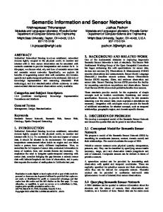
properties underwater, keeping in mind that the change in waterproofing membrane may contribute to the differences between the results for the current experiments with the Tmote Invent module and the previous experiments with the generic speakers. To obtain the signal quality of each frequency fi of a signal received from distance dj meters away, we apply a 100 Hz Equiripple [27] band pass filter centered at fi to the received signal. The filtered signal shape includes the transmitted tone at fi along with all the background noise within the frequency range fi − 50 to fi + 50. The background noise is distinguishable in all the temporal components of the signal during which the tone at fi is not transmitted. Through this filtering process, we can obtain the signal to noise ratio SN R(fi , dj ) of the channel for each frequency fi and distance dj . We performed the underwater experiments for distances dj ranging from 1 m to 13 m at 1m increments. At each distance dj , we conducted the measurements three times and obtained the average SN R(fi , dj ) of the three samples for fi . The value of µ is set to 1.5 as a compromise between cylindrical and spherical spreading. Figure 4 illustrates the Tmote Invent measured and theoretical SN R(fi , dj ) values for each frequency fi at each distance dj . The measured SNR in Figure 4 for certain frequencies between 1000 and 2000 Hz, such as 1300 Hz and 1500 Hz, is higher than the projected SNR for those frequencies. This effect is a reflection of the choice of 1.5 for the µ variable for the computation of the transmission loss. The higher values of the 17
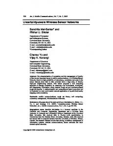
Fig. 5. Noise level of the underwater channel as observed by the PC microphone
measured SNR indicate that the signal spreading for these particular frequencies is closer to the cylindrical model than the spherical model, highlighting favorable multi-path and reflection effects for these frequencies in the closed testing environment. Another observation on Figure 4 is the frequency selective behavior of the channel (consisting of the Tmote Invent speaker, latex membranes, underwater medium, and PC microphone). To further investigate this frequency selectiveness of the channel, we compute the noise level of each frequency distance pair. To compute the noise level, we can use the transmission power Pt of the speakers to obtain It through Equation 3. We can then compute the source level SL through Equation 4. We can also get the transmission loss T L(fi , di ) through Equation 5 for every fi and dj . Using the measured values of SN R(fi , dj ), we can compute N L(fi , dj ) through equation 1. Figure 5 illustrates the noise level in the water at each frequency fi as observed at a receiver that is dj meters away from the sender. The apparent noise level is high at very low frequencies, and it drops steadily up until 1000 Hz. Between 1000 Hz and 2000 Hz, the noise level is generally similar except for minor fluctuations. The noise level then starts to increase again for frequencies above 2000 Hz. This highlights the favorability of the channel to frequencies between 1000 and 2000 Hz, indicating that response of the speaker/microphone pair and the acoustic coupling of the membrane with the water medium is best at these frequencies. We also note the slight but steady drop in noise level as the receiver moves further away from the sender. This 18
effect is attributed to a form of self-interference, similar to terrestrial networks, where a sender and receiver that are too close may exhibit high noise levels due to the high relative amplitude of the multi-path signal components at the receiver.
The underwater noise level results reflect not only the interference in the underwater channel, but also the response and coupling of the microphone, speaker, and elastic membrane with the underwater medium. This includes any distortions related to impedance mismatching caused by placing the components in an underwater medium, whereas they are typically designed for the aerial channel.
To put the underwater noise level results in perspective, we have performed similar medium profiling experiments in the aerial channel and derived the noise level of the microphone/speaker pair in air using the same method described above. The parameters for computing the SNR in air can be found in our earlier work in [32].
Figure 6 shows the aerial noise level for communication system. As for the underwater channel, the noise level reflects ambient interference as well as how well the components couple with the aerial medium. The results in Figure 6 exhibit similar behavior to the underwater channel for frequency at or below 2000 Hz, where very low frequency experience high noise levels and frequencies between 1000 and 2000 Hz experience reduced noise levels. A similar correlation between the apparent noise level and distance is also observed for the aerial channel, where self-interference decreases with distance. The main difference between the aerial and underwater noise levels occurs at short transmission distance and frequencies above 2000 Hz, where the underwater noise level increase steadily. In contrast, the aerial noise level increases slightly for frequencies just above 2000 Hz, and it remains relatively constant for higher frequencies. At transmission distances of 3m or higher, the self-interference exhibits a sharp drop for frequencies above 2000 Hz, resulting in significantly lower noise levels than the underwater channel for the same frequencies. This indicates that our system’s acoustic coupling is mostly unaffected for frequencies between 1000 and 2000 Hz when the nodes are placed in water, whereas it degrades for high frequencies.
Based on this frequency selectivity, the software acoustic modem can use the following 8 frequencies that exhibit the highest signal quality at all distances: 1000, 1200, 1300, 1500, 1600, 1700, 1800, and 2000 Hz. The minimum SN R for all of these frequencies within a range of 13 m is 6.95 dB. It is worth noting that only one of the above frequencies, 1300 Hz, is common with the top 8 frequencies for the PC speakers. We attribute this difference to the difference in waterproofing membranes, as well as the potential hardware differences 19
Fig. 6. Noise level of the aerial channel as observed by the PC microphone
of the two speakers. An attractive feature of implementing modulation in software is the capability for selfcalibrating modems that can profile the medium and determine the best set of frequencies and the suitable modulation rate for the channel.
4.2
Data Communication
Prior to conducting data communication experiments, we can compute the achievable error-free bit rate C for each communication distance using the Shannon-Hartley expression [30]: C = Blog2 (1 + SN R) bps
(7)
Based on the measured SNR of the selected frequencies of the software modem, we can project the achievable error-free bitrate of the Tmote Invent speakers for different communication ranges, using the lowest value of SNR for all the selected data frequencies. Figure 7 illustrates the projected error-free bitrate of the Tmote Invent speakers. For all distances up to 13 m, the measured SNR indicates that the speakers can support an error-free bitrate of at least 24 bps. In our software modem design and experiments, we choose to explore bit rates that exceed the expected channel capacity within a system that is tolerant of some communication errors. Our software modem 20
40 35 Bitrate (bps)
30 25 20 15 10 5 0 1
2
3
4
5
6 7 8 9 Distance (m)
10 11 12 13
Fig. 7. Error-free bitrate of Tmote Invent Speakers in the underwater environment
Symbols Received (%)
6bps
12bps
24bps
48bps
100 90 80 70 60 50 40 30 20 10 0 1
3
5
7 9 Distance (m)
11
13
15
17
Fig. 8. Percentage of symbols correctly received for the Tmote Invent speakers in the underwater environment
is based on a structure of time slots. Each time slot of length T milliseconds contains one FSK symbol, which has a duration of T /2 milliseconds, in addition to a guard time of T /2 milliseconds. Guard times between adjacent FSK symbols are necessary to avoid inter-symbol interference which may arise as a result of multi-path propagation effects. To evaluate the impact of the length of the time slot on the data reception capability at different distances, we consider 4 cases for the time slot lengths: (1) 500 ms; (2) 250 ms; (3) 125 ms; and (4) 62.5 ms. The above time slot lengths correspond to data bit rates of 6, 12, 24, and 48 bits per second respectively. Note that we refrain from conducting experiments for the 96 bps data rate, because of its poor performance in PC speaker experiments. The second set of experiments directly evaluates the data transmission capability of the Tmote Invent speakers. The encouraging results of the Tmote Invent medium profiling experiments (mainly the reduced dependence of signal loss on distance) have motivated the expansion of the range of the data transmission experiments to 17 m. Experiments at each distance between 1 and 17 m at 1 m increments are conducted 4 times, and the results represent the average of the four experiment instances. Figure 8 shows the percentage of symbols correctly received with the Tmote Invent speakers. Although we conducted the experiments at 1 m increments, we display the data transfer results for 2 m increments for clarity of presentation. For all bit rates in the experiments, the receiver could decode at least 79% of the 21
Transfer rate (bps)
6
12
24
48
Tmote+Latex membrane
≥95%
≥90%
≥81%
≥79%
N/A
≥90%
≥78%
≥35%
Up to 17m Generic+Vinyl membrane Up to 10m Table 1 Comparison of the percentage of symbols correctly received for the PC speakers and Tmote Invent experiments
transmitted symbols. Also, the decoding capability of the receiver with the Tmote Invent speaker is as good as or better than the PC speaker experiments, as Table 1 reveals. Note that the signal with a bit rate of 48 bps, where the signal decoding capability improves from 35% to 79%.
For data transfer rates of 12 and 24 bps, the percentage of correctly received symbols is the same for the Tmote Invent and our earlier PC speaker experiments. However, we note that the Tmote Invent speaker with the latex membrane provides the same data transmission capability at 17 m as the PC speakers with the vinyl membrane at 10 m. Again, this confirms the superior performance of the latex membrane to the vinyl membrane as a waterproofing solution for our application.
5
5.1
Discussion and Conclusion
Communication Range
The empirical results from this study serve as a proof-of-concept for software-driven underwater communication through generic acoustic hardware with data rates in the order of tens of bits per second. It is worth noting that the communication range of 17 m in this study is a limitation of the available physical space and not a technical communication limitation. An interesting direction for future work is to push the technology further to evaluate the maximum achievable communication and detection ranges, and the associated data transfer rates. In fact, an extrapolation of the experimental results reveals that the theoretical channel capacity at 50 m still remains above 16 bps. 22
5.2
Network Topology
The current implementation of our software-driven acoustic underwater networks communication system, which relies on the Tmote Invent speakers as transmitters, and a generic PC microphone as receiver, enables the deployment of a single-hop network centered at the base station with a theoretical circular shape and a radius of at least 17 m. The Tmote Invent modules send their data through direct acoustic links to the base station, forming a cluster of underwater motes that provides environmental data with high spatial granularity within the coverage area. The deployment of several 1-hop clusters can cover wider geographic areas through a hierarchical topology in which the clusterheads send the collected data to a central repository for dissemination and analysis. Such a topology is especially useful for pinpointing the propagation areas of oil patches along a coastline in the aftermath of oil spills, such as the catastrophic oil spill off the coast of Lebanon resulting from the recent hostilities there.
5.3
Low Power Communication
The limited communication range of our system stems from the ultra lower output power of the speaker. Our network architecture adopts a multi-hop topology of low-power communication links for enabling dense underwater sensor networks. The multi-hop topology of our network aims at limiting disruption to marine wildlife. Sending sound waves underwater can cause disorientation of the marine wildlife, such as whales and dolphins. Recently, there have been several incidents in which whales or dolphins were disoriented and stranded because of human noise pollution resulting from sonar, oil exploration, and shipping [35]. Avoiding adverse effects on marine biology is a major consideration for environmental preservation. Because our network relies on multi-hop short range low power links between sensor nodes, it minimizes sound interference with the marine wildlife.
5.4
Data Transfer Rate
The achievable bit rate of our system, in the order of tens of bits per second, is sufficient for long-term monitoring sensor networks, such as for environmental or habitat monitoring. The nodes sample their sensors and send the data once during each update period, typically in the order of minutes. Since each node must send only a handful of sensor values during each update period, a data transfer rate in the order of tens 23
of bits per second provides more than enough throughput to communicate all the sensor values during an update period.
5.5
Communication Protocols
Deploying our communication system within an unattended underwater sensor network involves several open research challenges, such as the design of Medium Access Control and routing mechanisms. For instance, the underwater nodes should ensure that their data packets do not collide, which requires the use of carrier sensing or handshake messaging prior to data transmission. Such collision avoidance mechanisms include either energy overhead or delay overhead or both. Energy efficiency is always a major concern for in-situ sensor networks because recharging or replacing node batteries is difficult, especially in hard-to-access areas such as the underwater environment. Any MAC or routing layer mechanisms for ensuring proper data delivery must also provide energy-efficient behavior. The main challenge is therefore the design of higher layer communication mechanisms that serve the needs of the user application while balancing the energythroughput-delay tradeoff. A prominent trend for managing this tradeoff in ad hoc and sensor networks is the design of cross-layer mechanisms that cut across traditional layer boundaries to achieve fine-grained optimizations [36].
5.6
Deeper Waters
Our proposed solution currently relies on latex membranes to waterproof the sensor modules, so the volume, the shape, and the resonance frequency range of the enclosing latex membrane could change in deeper waters, where vertical pressure increases. The increased pressure at higher depths also causes a change in bulk modulus and density of the water, leading to increases in sound speed of 0.017 m/sec for every meter of depth increase [24]. This slight change causes a sound beam to bend upward at great depths, whereas our model considers straightforward propagation [16]. Furthermore, the noise profile and channel model for deeper waters is not yet deterministic, so the exact SNR profile and data communication range and rate remain open issues for further investigation. 24
5.7
Cost and Scale Considerations
A main motivator for using software modems is the reduction in cost and the increase in spatial scale of the network. This section considers a typical scenario that requires the coverage of a 1km stretch of river or coastline with sensor nodes. We explore the associated cost and spatial scale of covering this stretch with hardware and software modems. In the case of hardware acoustic modems that have communication ranges in the order of kilometers, a single node is sufficient to cover the entire 1km stretch and communicate the data to shore. The average cost for a single underwater node that combines a hardware modem, transducer, and casing is about US$ 7,500 according to our survey of multiple vendors [9, 10]. In the case of software acoustic modems, the current price per Tmote Invent node is US$ 250, and mass production price is expected to drop prices to below $ 10 per node [25]. The transmission coverage range of software modems on Tmote Invent modules is in the order of tens of meters, realistically running between 10 and 100 meters at best (see Section 4). Given their limited range, multiple nodes are required for covering the 1 km stretch. The need for multiple nodes to cover the same physical area covered by a single node with a hardware modem actually improves the spatial scale of the network, as it provides more data points from the same physical area. Figure 9 plots the network cost per km as a function of internode distance and price per node. The transparent plot in Figure 9 corresponds to the software modem cost, and the solid plot corresponds to the hardware modem cost, which is constant at US $7,500. In the worst case, the network cost for the software modems is about $25,000 per km for an internode distance of 10m and a unit price of $250. In this case, the network cost is about 3.5 times the cost of hardware modem networks, but the network provides a 100 fold increase in spatial granularity. When the unit price drops to $100, the software modem network cost is only 33% higher than the hardware modem network, while still providing a 100 fold increase in spatial scale. For an internode distance of 20m (which conforms with the communication range results in this paper) and a unit cost of $100, the software modem network cost is 33% less than hardware modem network cost, and it still provides a 50 fold increase in spatial scale. In fact, any unit price below $220 or any internode distance above 30m result in significant increases in network spatial scale and in reductions in network cost. In the most optimistic case of $10 for unit cost, savings range between $6,500 and $7,400 depending on internode distance. 25
Fig. 9. Cost comparison for covering a 1-km stretch of water
In sum, this paper has proposed software-driven acoustic underwater sensor networks for short-range shallow water monitoring. The network architecture provides both high spatial scale and high temporal scale at relatively low cost through the use of generic acoustic hardware on board off-the-shelf sensor motes. Because the cost of our system is limited to the relatively cheap sensor module, we expect the system to promote wider and denser deployments of underwater sensor networks.
acknowledgement
The work of RJ has been supported by the IRCSET Embark Award. The work of CVL has been supported in part by NSF grant No. CCF-0347902.
References
[1] M.Stojanovic. “Underwater Wireless Communications: Current Achievements and Research Challenges,” IEEE Oceanic Engineering Society Newsletter, Spring 2006. [2] B. Sauser.
“Networking the Hudson River,”
Technology Review, Published by MIT. August, 2007. available:
http://www.technologyreview.com/Infotech/19309/ [3] J. G. Proakis, E. M. Sozer, J. A. Rice, and M. Stojanovic. “Shallow Water Acoustic Networks,” IEEE Communications Magazine, November 2001. [4] J. Cui, J. Kong, M. Gerla, and S. Zhou. “Challenges: Building Scalable Mobile Underwater Wireless Sensor Networks for Aquatic Applications,” IEEE Network, 20(3):12–18, 2006. [5] I. F. Akyildiz, D. Pompili and T. Melodia. “Underwater acoustic sensor networks: research challenges,” Ad Hoc Networks (Elsevier), vol. 3, no. 3, pp. 257-279, March 2005.
26
[6] I. Vasilescu, K. Kotay, D. Rus, M. Dunbabin and P. Corke. “Data Collection, Storage, and Retrieval with an Underwater Sensor Network,” In Proc. Sensys’ 05, San Diego, CA, 2005. [7] J. Heidemann, Y. Li, A. Syed, J. Wills, and W. Ye. “Underwater Sensor Networking: Research Challenges and Potential Applications,” USC/ISI Tech. Rep. ISI-TR-2005-603, 2005. [8] X. Yang et al. Design of a Wireless Sensor Network for Longterm, In-Situ Monitoring of an Aqueous Environment. Sensors, 2:455-472, 2002. [9] Linkquest Inc. available at: www.link-quest.com [10] DSPComm. available at: www.dspcomm.com [11] R. A. Iltis, H. Lee et al. “An Underwater Acoustic Telemetry Modem for Eco-Sensing,” In proc. Oceans’05, September 2005. [12] Utility Acoustic Modem available at: auvlab.mit.edu [13] J. Wills, W. Ye, and J. Heidemann. “Low Power Acoustic Modem for Dense Underwater Sensor Networks,” In Proc. IEEE (WUWNet06), 2006. [14] C. V. Lopes and P. Aguiar. “Acoustic Modems for Ubiquitous Computing,” IEEE Pervasive Computing, 2003. [15] Blauert, Jens (Ed.) Communication Acoustics. Springer, 2005. [16] R. J. Urick. Principles of Underwater Sound. Mcgraw-Hill, 1983. [17] J. Groen, J.C. Sabel and A. Htet. Synthetic aperture processing techniques applied to rail experiments with a mine hunting sonar. In Proc. UDT Europe, 2001. [18] R. Jurdak, C.V. Lopes, and P. Baldi. “Software Acoustic Modems for Short Range Mote-based Underwater Sensor Networks,” In Proc. of IEEE Oceans Singapore. May, 2006. [19] R. Jurdak, P.M.Q. Aguiar, P. Baldi, and C.V. Lopes. “Software Modems for Underwater Sensor Networks,” In proc. of Oceans.’07. June, 2007. [20] R. Jurdak, A.G. Ruzzelli, G.M.P. O’Hare, and C.V. Lopes. “Reliable Symbol Synchronization in Software-Driven Acoustic Networks,” In Proc. of IEEE GlobeCom Washington D.C. November, 2007. [21] N. Fruehauf and J.A. Rice. System design aspects of a steerable directional acoustic communications transducer for autonomous undersea systems. In OCEANS, volume 1, pages 565 –573. IEEE, 2000. [22] F. H. Fisher and V. P. Simmons. “Sound Absorption in Sea Water,” J. of Acous. Society of America, 62:558, 1977. [23] S.
A.
L.
Glegg,
R.
Pirie,
and
A.
LaVigne.
A
study
of
ambient
noise
in
shallow
water,
available:http://www.oe.fau.edu/ acoustics/. [24] F. H. Fisher. “Effect of High Pressure on Sound Absorption and Chemical Equilibrium,” J. of Acous. Society of America, 30:442, 1958. [25] M. Hatler and C. Chi. Wireless Sensor Networks: Growing Markets, Accelerating Demand, On World Report, 2005. available: http://www.onworld.com/html/wirelesssensorsrprt2.htm [26] R. Jurdak, C.V. Lopes, and P. Baldi. “An Acoustic Identification Scheme of Location Systems,” In Proc. ICPS’04, 2004.
27
[27] Cetin, A.E. Gerek, O.N. Yardimci, Y. “Equiripple FIR filter design by the FFT algorithm,” In IEEE Signal Processing Magazine, 14(2):60–64, 1997. [28] M. Stojanovic. Recent advances in high speed underwater acoustic communications. Oceanic Engineering, 21(4), 1996. [29] P. Chapman, D. Wills, G. Brookes, and P. Stevens. Visualizing Underwater Environments Using Multi-frequency Sonar. In IEEE Computer Graphics and Applications, 1999. [30] C. E. Shannon. “A mathematical theory of communication,” Bell System Technical Journal, volume 27, pp. 379-423 and 623-656, July and October, 1948. [31] Rincon Research Corporation. BlackBook. available:tinyos-1.x/contrib/rincon/tools/java/com/rincon/blackbook [32] R. Jurdak, P. M. Q. Aguiar, C.V. Lopes, and P. Baldi. “A Comparative Analysis and Experimental Study on Wireless Aerial and Underwater Acoustic Communications,”
Proceedings of the IEEE International Conference on Digital
Telecommunications (ICDT). Cap Esterel, France. August, 2006. [33] MoteIV Corporation available at: www.moteiv.com [34] Tiny Operating System. UC Berkeley available at: www.tinyos.net [35] R.
Black.
“Research
Needed
on
Marine
Sound,”
BBC
News
article,
news.bbc.co.uk/2/hi/science/nature/4706670.stm [36] R. Jurdak. Wireless Ad Hoc and Sensor Networks: A Cross-Layer Design Perspective. Springer-Verlag, 2007.
28
available: