September 28, 2010
17:39
World Scientific Review Volume - 9in x 6in
software˙driven
Chapter 1 Software Driven Underwater Acoustic Sensor Networks
Raja Jurdak∗ CSIRO ICT Centre, Pullenvale QLD Australia,
[email protected] Deployment efforts of underwater acoustic sensor networks have been impeded by the prohibitive monetary cost and high power consumption of existing acoustic hardware, which typically targets deep water long range communication. To address this issue, we propose software-driven underwater networks that rely on widely available speakers and microphones in electronic devices, coupled with software modems, to establish wireless acoustic communication links. The proposed acoustic communication system paves the way for cheap and easily deployable underwater acoustic sensor networks for marine monitoring applications with low data transfer requirements. This chapter presents the components that comprise the underlying communication system for software-driven underwater sensor networks, with an eye towards their application opportunities. Based on our recent experiments in rivers, canals, and ponds, we also address the technical challenges for software-driven underwater sensor networks, including modulation, symbol synchronization, filtering, and demodulation, as well as logistical challenges, such as calibration, fouling, and waterproofing, which typically arise in underwater environments. The discussion yields suitable guidelines for next steps in software-driven underwater sensor network research and development.
1.1. Introduction Recent improvements in the processing power, memory size, form factor, and battery consumption of sensor modules have fueled increased interest in the development and deployment of underwater acoustic sensor networks. The diversity in the potential application space for underwater sensor networks, including oil prospecting, seismic and environmental monitoring, ∗ Raja
Jurdak is a Principal Research Scientist at CSIRO ICT Centre. 1
September 28, 2010
2
17:39
World Scientific Review Volume - 9in x 6in
software˙driven
R. Jurdak
and military applications, has led to related projects with a wide range of design requirements.4–6 Interest in monitoring aquatic environments with sensor networks stems from their capability to provide sensorial data at unprecedented spatial and temporal scales. So far, aquatic monitoring platforms have attempted to capture information at high temporal scale (for example, surface buoys with suspended probes in the water, satellites that observe large geographic regions) or high spatial scale (for example, research vessels that survey sea floors). Until the recent advent of sensor networks, monitoring aquatic environments at both high temporal and spatial scales had remained an elusive goal, despite the strategic significance of water management to the social and economic development of the global population. Most underwater acoustic sensor network efforts rely on specialized hardware for modulating, transmitting, receiving and demodulating acoustic signals. The specialized modulation hardware ranges from powerful and expensive commercially available acoustic modems7,8 to dedicated integrated circuits4 and dedicated DSP boards.9–11 The communication hardware ranges from specialized underwater acoustic transducers and hydrophones5 to generic speakers and microphones.4 The use of specialized hardware for establishing acoustic communications underwater typically increases the network cost, the design time spent in interfacing node hardware components, and the size and weight of individual network nodes. The focus of recent efforts on hardware acoustic modulation considers that low processing speeds do not allow the modulation of acoustic signals in software. However, modulation and demodulation of acoustic signals in software demonstrated its success in both aerial12,14 and underwater15,16 environments. Software modulation is an alternative approach to expensive hardware modems that overcome most of the cost and complexity drawbacks. Recent advances in miniaturization and circuit integration have yielded smaller and more powerful processors that are capable of efficiently running acoustic modulation and demodulation software. Software modulation also provides a higher level of flexibility for on-the-fly tuning of modulation parameters to suit different environments. The transmission and reception of the software modulated acoustic signal can also avoid using specialized hardware through generic speakers and microphones. Eliminating the need for specialized hardware for acoustic communication greatly reduces the cost of network nodes, which facilitates the dense deployment of mote-class nodes to form underwater sensor networks. Within this context, this chapter proposes software-driven under-
September 28, 2010
17:39
World Scientific Review Volume - 9in x 6in
Software-Driven Underwater Networks
software˙driven
3
water acoustic sensor networks for dense shallow water quality monitoring in rivers, bays, estuaries, and lakes. The network consists of affordable off-the-shelf sensor modules (motes) that use software modems and generic hardware to communicate acoustically and send the data towards the base station through multi-hop communication. The motes are placed into elastic latex membranes that waterproof the hardware while maintaining acoustic coupling with the water channel. In addition to being cost-feasible and satisfying the temporal and spatial scale requirements, sensor motes, which are originally designed for terrestrial applications, combine processing and storage capabilities that provide an intelligent platform for network selfconfiguration and self-management. Finally, the speakers on board the mote platform have low output power, which is favorable for both network longevity and for minimizing interference with aquatic ecosystems. This chapter discusses the design, application opportunities, and challenges of software-driven underwater sensor networks. Software-driven underwater sensor networks target long-term shallow aquatic monitoring applications, and they involve the design and development of the acoustic communication links, communication protocols, and application behavior. In particular, this chapter investigates the design and development of reliable acoustic communication for realizing software-driven underwater sensor networks. The remainder of this chapter is organized as follows. Section 1.2 discusses the related work on underwater network architectures and on both hardware and software acoustic modems. Section 1.3 presents the network architecture and focuses on the physical layer functionality and higher layer communication protocol issues. Section 1.4 discusses the logistical challenges that face software-driven underwater sensor network deployments, while section 1.5 concludes the chapter. 1.2. Related Work This section first reviews existing architectures for underwater networks. The latter part of the section discusses acoustic modulation, both in hardware and in software, as an enabler of wireless underwater communication. 1.2.1. Underwater Network Architectures Most underwater network proposals rely on wireless acoustic communication between a set of underwater nodes, which eventually relay information
September 28, 2010
17:39
World Scientific Review Volume - 9in x 6in
4
software˙driven
R. Jurdak
to a node at the surface. Akyildiz et al.3 define both 2-dimensional and 3-dimensional architectures for underwater networks. The 2-dimensional architecture follows a clustered topology in which each group of underwater nodes that are fixed to the sea floor communicates with more powerful nodes, or clusterheads, in their vicinity. The clusterheads then relay the data to a surface node, which in turns forwards the data through satellite or long range radio links to a central repository. The 3-dimensional architecture considers underwater sensor nodes that are anchored to the sea-floor, thus allowing them to float at different depths depending on currents and tides. Since our chapter considers shallow water applications with communication at very short ranges, differences in depth are relatively small so the network adheres to the 2-dimensional architecture. Another recent survey by Cui et al.2 classifies underwater network architectures according to their deployment duration and the criticality of data they sense, differentiating between two architecture classes: long-term non-critical deployments; and short-term critical deployments. Their article also identifies very short range underwater acoustic modems as a gap in the current state-of the art. Our work coincides with the long-term non-critical monitoring architecture of Cui et al., and in this paper we specifically target the development and investigation of low power acoustic modems for very short range underwater networks. Vasilescu et al.4 propose another network architecture where autonomous underwater vehicles (AUV) periodically visit the network area to collect data from the in-situ sensors through ultra short wireless acoustic links. Although our work focuses on the adaptation of stationary mote platforms for the underwater environment, the development of acoustic communication links that operate with a range of about 20m on the motes would enhance Vasilescu’s architecture, reducing the localization and navigation requirements, as well as the duration of the data collection process by the AUV. 1.2.2. Hardware Modems Earlier efforts in acoustic communication have focused on using specialized and dedicated hardware for underwater acoustic modulation and demodulation. Acoustic underwater communication is a mature field and there are several commercially available underwater acoustic modems.7,8 The commercially available acoustic modems provide data rates ranging from 100 bps to about 40 Kbps, and they have an operating range of up to a few km
September 28, 2010
17:39
World Scientific Review Volume - 9in x 6in
Software-Driven Underwater Networks
software˙driven
5
and an operating depth in the order of thousands of meters. The cost of a single commercial underwater acoustic modem is at least a few thousand US dollars. The prohibitive cost of commercial underwater modems has been an obstacle to the wide deployment of dense underwater networks, until the recent development of research versions of hardware acoustic modems. Researchers at the Woods Hole Oceanographic Institution are developing a Utility Acoustic Modem (UAM) as a completely self-contained, autonomous acoustic modem capable of moderate communication rates with low power consumption.10 This modem uses a single specialized DSP board with on board memory and batteries. The purpose of developing the UAM is to make a more affordable acoustic modem available for the research community. Researchers at UC, Santa Barbara are also developing a hardware acoustic underwater telemetry modem9 for ecological research applications, using a DSP board with custom amplifiers, matching networks, and transducers. Their modem is intended for interfacing to nodes in an underwater ad hoc network, and it achieves a 133 bps data rate. Whereas both of the above efforts 9,10 aim at making underwater acoustic modems cheaper and more accessible by developing specialized affordable hardware, our work aims at driving the cost even lower and at making acoustic underwater communications even more pervasive through the development of software acoustic modems that can operate on generic hardware platforms. In a more recent article, Wills et al.11 propose their design for an inexpensive hardware modem for dense short-range underwater sensor networks. Their work aims at borrowing communication concepts, such as wake-up radio, from terrestrial sensor networks. Although we share the same end goal as Wills et al. (inexpensive acoustic modems for dense short-range wireless networks), our approach differs in its emphasis on modulation through software rather than through specialized hardware.. One of the few attempts to deal with generic microphones and speakers is Vasilescu et al.4 These authors propose a network that combines acoustic and optical communications, stationary nodes and AUV’s for monitoring coral reefs and fisheries with ranges in the order of hundreds of meters. Their work uses generic microphones and speakers along with a specialized integrated circuit that generates ASK or FSK modulated sound signal in order to demonstrate the acoustic communication capability underwater. Vasilescu et al. achieve a bit rate in the order of tens of bits per second up to about 10 to 15 meters. Although our work resembles their work in the use of generic microphones and speakers for acoustic communications, it differs in its proposal and implementation of software modems for off-the-
September 28, 2010
17:39
World Scientific Review Volume - 9in x 6in
6
software˙driven
R. Jurdak
shelf mote platforms rather than the use of specialized integrated circuits for communication.
1.2.3. Software Modems With the rapid increase in processor speeds, the idea of implementing acoustic modems in software becomes feasible and even attractive due to the low cost processing power. Coupling software acoustic modems with the use of microphones and speakers for transmission and reception can eliminate the need for specialized hardware for acoustic communication, trading off cheap computational power for expensive communication hardware. The cost of software acoustic modems is limited to the development cost, after which the per unit cost is zero. Because of these attractive features, Lopes and Aguiar12 have investigated using software modems for aerial acoustic communications in ubiquitous computing applications. Building on their work, software acoustic modems can also eliminate the need for specialized hardware in underwater acoustic communications, thereby encouraging wider deployment of underwater sensor networks. In preliminary experiments, we started profiling the underwater acoustic spectrum and data communications capabilities with software acoustic modems.15 Our work used waterproofed generic microphones and speakers, connected to laptops on the surface, for sending and receiving software modulated acoustic signals. The achieved bit rates were in the order of tens of bits per second for distances up to 10 meters. Our work here extends our earlier work by coupling software modems with Tmote Invent module hardware. Our recent study16 presents underwater experiments results that confirm the communication capability of software modems on Tmote Invent hardware. This chapter further investigates the application opportunities and the technical and logistical challenges of this communication system.
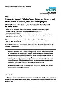
1.3. Software-Driven Underwater Acoustic Sensor Networks This section describes the architecture for software-driven underwater sensor networks. Figure 1.1 sheds more light on the target network application.
September 28, 2010
17:39
World Scientific Review Volume - 9in x 6in
Software-Driven Underwater Networks
Broadband Radio Connection To Internet
Underwater sensor nodes
Fig. 1.1.
7
Interactive Maps
Surface Buoy
Wireless acoustic links
software˙driven
data repository
Query and Download tools
Target network application
1.3.1. Network Overview Software-driven underwater sensor networks will consist of tens to hundreds of motes deployed in a shallow water environment. The motes can communicate acoustically through short-range wireless links, thanks to their on-board speaker and microphone and to software acoustic modems. The motes are placed into elastic latex membranes, which maintain the acoustic coupling of the on-board speaker and microphone with the water, while waterproofing the motes. The modules periodically sample their sensors, collecting physical indicator data from their built-in sensors, such as water temperature or tidal strength, or from add-on sensors, such as salinity or phosphorous levels, which help determine water contamination levels. After sampling their sensors, the nodes send the sensor values to neighboring nodes, which in turn relay the data through multi-hop links to the nearest collection point. Because each node periodically sends only few 2-byte sensor values, the data transfer rate requirements of the network are low. The network architecture supports two embodiments of the collection point: (1) an underwater instrumentation station that relays network data to a data repository on shore through a sub-sea fibre optic cable; or (2) a surface station that resides on a buoy and relays network data to the data repository on shore through a long range RF communication link. For both configurations, the logical network topology is a tree, or more generally, a multiple-tree topology, in the case of several collection points. 1.3.2. Motivating Application Software-driven underwater acoustic sensor networks support shallow water aquatic application scenarios that require long-term dense monitoring of a
September 28, 2010
17:39
8
World Scientific Review Volume - 9in x 6in
software˙driven
R. Jurdak
given physical area. A representative scenario is the monitoring of inland water bodies, such as rivers, lakes, and estuaries. In particular, IBM and the Beacon Institute have recently announced a joint project to monitor the Hudson River and to provide real-time minute-by-minute environmental data from within the river.1 The collected environmental data includes salinity, temperature, dissolved oxygen, and pollution loading. This project aims to develop multiple new technologies and mechanisms for capturing, collecting, aggregating, disseminating, and analyzing data. One challenge in this project is the dimensions of the area to be monitored, which spans long distance with a more or less constant width. These dimensions, coupled with numerous natural bends in the river path, preclude the use of traditional oceanic communication paradigms that assume an open line-of-sight communication channel. Short range communication systems, such as software-driven underwater sensor networks, provide an appropriate monitoring solution for river monitoring, as nodes can use multi-hop communication links and bypass obstacles such as river bends. Furthermore, the use of short range communication links demands dense deployments of sensor nodes, which is cost-feasible only if the individual node cost is small. Again, softwaredriven underwater sensor networks satisfy this requirement, as the unit cost is currently small and continuously decreasing as mass production of sensor nodes rises. The dense deployment actually improves the spatial granularity of the river monitoring application, because it increases the available data points for the same physical area.
1.3.3. Target Platform For our application, we have selected mote-class computers, which are powerful enough to perform sufficient in-network processing and are affordable enough to enable the deployment of a dense network at reasonable cost. In particular, we have selected the Tmote Invent module (shown in Figure 1.2) which has an on-board SSM2167 microphone from Analog Devices sensitive to frequencies from 100Hz to 20kHz, and an on-board TPA0233 speaker amplifier from TI with an 8 ohm speaker that has a range of 400Hz to 20kHz. The goal of this work is to exploit the on-board microphone and speaker to establish short range acoustic links among Invent modules. The next subsection reviews the basic concepts of underwater acoustics that driven the design of our software modem.
September 28, 2010
17:39
World Scientific Review Volume - 9in x 6in
Software-Driven Underwater Networks
Fig. 1.2.
software˙driven
9
The Tmote Invent module
1.3.4. System Components Figure 1.3 illustrates the main components of the communication system. At the sender side, digital sensor data from the underwater environment first enter the software modulator, resulting in a modulated acoustic signal. The on-board speaker then transmits this signal into the underwater channel. At the receiver, the on-board microphone captures the signal and the resident software performs symbol synchronization through the S 4 block,17 filtering through FFT or wavelet decomposition, and finally demodulation.
Digital data
Modulator
Modulated acoustic signal
Transmitted acoustic signal Speaker
(a) Received signal at microphone
Microphone
S4
Filter (Bandpass or FFT)
Synch
Demdoulator
(b)
Fig. 1.3. Block diagram for software modem (a) Modulator/Transmitter (b) Demodulator/Receiver
1.3.4.1. Modulation The first component of the acoustic communication system is software modulation, that takes digital data as input and modulates an acoustic signal with the data. The potential choices of modulation schemes for software
September 28, 2010
10
17:39
World Scientific Review Volume - 9in x 6in
software˙driven
R. Jurdak
modems include amplitude shift keying (ASK), phase shift keying (PSK), and frequency shift keying (FSK). We have selected FSK as the lowest complexity mechanism to run on the resource-limited mote platforms. In general, FSK uses 2N frequencies to encode N bits per frequency. The signal demodulation at the receiver can use low complexity techniques, such as the Fast Fourier Transform (FFT) or wavelet decomposition, to determine the frequency content of the signal. Choosing a number of frequencies that have high signal-to-noise ratio (SNR) for the channel and ensuring sufficient spectral separation between the frequencies for FSK provides robust underwater communication for low power transmissions with minimal processing complexity at the receiver. We recently performed an empirical study to investigate the spectral properties of the underwater channel in a controlled water environment.16 The study used the Tmote Invent18 speaker as the transmitter of acoustic signals and a generic PC microphone as the receiver. The components were waterproofed using off-the-shelf elastic latex membranes that vibrate sufficiently to preserve most the acoustic properties of the speaker and microphone. The study evaluated the signal-to-noise ration (SNR) of frequency tones between 400 and 6700 Hz at 100 Hz increments. The selection of the 100 Hz band separation between frequencies provides for low complexity frequency detection at the receiver. Note that narrower separation bands enable the use of more frequencies within the same available bandwidth, which increases bit rates but also reduces signal quality at the receiver. In general, there is a tradeoff in digital modulation techniques between the number of signal levels (in phase, amplitude, or frequency) and the quality of the signal. In our case, increasing the number of frequencies by using narrower frequency bands requires the use of higher order filters or fast fourier transforms (FFT) at the mote to decode the signal, which is a processingintensive task. This is not favorable to the limited processing power of the motes. The study revealed that the channel, which includes the speaker, latex membranes, the water, and the microphone, exhibits the highest SNR at frequencies in the range of the 1000 Hz to 2500 Hz. The SNR drops steadily at frequencies above 3 Khz. Building on these results, we designed a software FSK modem that uses 8 frequencies in the 1-2.5 Khz range to represent 8 symbols of 3 bits each. The testing of the modem investigated 4 different bit rates from 6 bps to 48 bps, by varying the symbol duration from 500 ms to 62.5 ms. The experiment results revealed a low bit error rate for all data transfer rates within a transmission distance of 17 m, which
September 28, 2010
17:39
World Scientific Review Volume - 9in x 6in
software˙driven
Software-Driven Underwater Networks
11
was the size of the testing area. The output of the modulator block is a modulated acoustic signal that is then transmitted over the wireless medium through the built-in speaker. 1.3.4.2. Symbol Synchronization
f1 f2
data
f1 f2
Fig. 1.4. A sample showing the signal shaper as generated with the Tmote Speaker, with the preamble and postamble S 4 symbols at beginning and at the end of the signal.
The transmitted signal is received by the microphone at a remote node, on which the software then proceeds in the decoding process. Essential to acoustic communication with software modems is the ability of the receiver to synchronize to the first symbol of an incoming data stream. Traditional symbol synchronization approaches rely on the transmission of a predefined sequence of symbols, often referred to as a training sequence. The conventional approach makes two assumptions about the communication channel that do not hold for software-driven acoustic communications, namely: (1) a bit rate at least in the order of tens of kilobits per second; (2) a bit error rate (BER) in the order of 10−6 or lower. Software-driven acoustic communication, both aerial and underwater, supports lower bit rates that range between tens to hundreds of bits per second.15,16 In addition, the bit error rate of software-driven acoustic communication is several orders of magnitude higher than the radio frequency bit error rate. The higher bit error rate in acoustic communications tends to cause loss of training sequence symbols, preventing proper symbol synchronization. Furthermore, providing high redundancy in the training sequence to mitigate training symbol
September 28, 2010
17:39
12
World Scientific Review Volume - 9in x 6in
software˙driven
R. Jurdak
losses is not an option for the narrow usable bandwidth of software-driven acoustic communications. We recently proposed and tested a synchronization mechanism,17 that uses Short Signature Synchronization Symbols (S 4 ) to align symbol boundaries at the receiver. The design of the signature symbol aims at a high probability of correlation at the receiver even in cases of partial loss of the symbol and at low probability of false synchronization with ambient noise or data symbols. To this end, the symbol features include two square waves, with each square wave transmitted at a predefined frequency, separated by a predetermined guard time. Figure 1.4 shows a sample signal with an S 4 preamble and post-amble. The use of two frequencies for the signature symbol mitigates the effects of frequency selective fading or interference. The signature symbol guard time duration is chosen so that it is not equal to, and not a constant multiple of, the inter-symbol guard times to avoid high correlation with data symbols. The output of the S 4 provides the index of the first data sample in the received signal. 1.3.4.3. Filtering The receiver then proceeds to filter the received signal. Filtering the acoustic signal at the receiver minimizes the effect of out-of-band noise on the decoding process. A suitable choice of filtering method depends highly on the processing capability of at the receiver. Our system currently provides two filtering methods, with the first method employing narrow bandpass filters at the relevant frequencies. The second filtering method applies an FFT to the received signal and examines the signal amplitude at the FFT samples corresponding to the relevant frequencies. The narrowband filtering method provides a finer signal quality as it only focuses on the frequencies of interest and excludes all interference outside this spectrum. The superior performance of the narrowband filtering method comes at the cost of higher processing activity at the receiver. In fact, the narrowband filtering method is suitable for running on a PC or a PDA that acts as a base station for the underwater network, as in Figure 1.1. The FFT method can run on the motes themselves as it has lower processing complexity. Running the FFT method on motes enables the deployment of a multi-hop network where nodes can autonomously decode, process, and relay received signals. The FFT method provides a coarser signal quality than filtering since it does not exclude interference from outside
September 28, 2010
17:39
World Scientific Review Volume - 9in x 6in
Software-Driven Underwater Networks
software˙driven
13
the frequency spectrum of interest. 1.3.4.4. Demodulation The filtered signal then proceeds to the demodulator component. The demodulator begins examining the signal at the first data sample, which has been determined by the S 4 block. Starting at the first data sample and taking the number of samples that corresponds to one symbol, the demodulator determines the frequency component with the highest amplitude within this window, and outputs the data symbol corresponding to the highest frequency. For subsequent bits, the demodulator shifts the start sample of the previous symbol by the symbol length, and repeats the process of determining the strongest frequency component. 1.3.4.5. Communication Protocols The design of the higher layer communication protocols for this system should adopt a minimalist approach to avoid creating high overhead in this bandwidth- and energy-limited system. The MAC protocol design for underwater sensor networks cannot exploit traditional low duty cycle protocols for terrestrial sensor networks. The reason is that the energy cost of transmission is generally much higher than the cost of signal reception in underwater networks, whereas the cost of transmission and reception is almost the same in terrestrial sensor networks.19 Thus, signal transmissions dominate the energy consumption profile of underwater nodes. As such, the MAC protocol design should minimize control overhead messages, such as request to send (RTS) and clear to send (CTS), rather than implementing sleep policies. One possibility is to use burst tones at the beginning of transmission to reserve the channel. In particular, the S 4 preamble can serve as a burst tone for reserving the channel at the MAC layer. For routing data towards the surface node, our communication system advocates the use of short multi-hop links for deploying dense underwater sensor networks. Keeping in line with the system’s minimalist approach, the network should make use of simple multi-hop routing techniques, such as the directed broadcast with overhearing method of MERLIN.20 The relatively low cost of receiving signals actually favors the use of overhearing. Our recent study on the upper bounds for transmissions in directed broadcast networks with overhearing has shown that this method has only few redundant packet, resulting in low overhead for large networks.
September 28, 2010
14
17:39
World Scientific Review Volume - 9in x 6in
software˙driven
R. Jurdak
The design of all communication protocols for software-driven underwater sensor networks must follow a minimalist cross-layer22 approach that couples layer functionalities when possible in order to efficiently utilize the scarce bandwidth and energy resources of the nodes. For example, the synchronization symbols in S 4 may serve the dual purpose of node identification, typically a MAC layer feature, and symbol synchronization, a physical layer mechanism. Such cross-layer optimization reduces the control overhead of the communication system, enabling better utilization of the available channel bandwidth. 1.4. Logistical Considerations This section discusses the logistical challenges that face software-driven underwater sensor network deployments. 1.4.1. Waterproofing and Casing The most common waterproofing method for underwater communications hardware is to place the hardware in a custom-designed waterproof case with a special air-locked hole for the hydrophone and transducer that are in contact with the water. The cost associated with the material and design of the custom-designed casing strategies significantly increases system cost and discourages large scale deployments of underwater sensor networks. Our project’s design strategy advocates the use off-the-shelf components not just for communication and sensing, but also for the protection and waterproofing of the components. As such, our design places the sensor nodes in elastic latex membranes that are cheap and readily available on the market. The latex membranes take the form of a balloon that is sealed at the mouth to waterproof the sensor nodes. Since the sensor module includes the speaker and microphone, these acoustic communications components are also fully enclosed within the latex membranes. The elasticity of the membranes ensures that the acoustic waves transmitted by the speaker are transferred to the water through the elastic membrane. At the receiver side, the membranes vibrate upon the reception of an acoustic signal, transferring the signal from the water channel to the interior of the membrane where the microphone can detect it. The use of the latex membranes causes relatively small reductions in signal amplitude. Our recent study compared the suitability of two membranes for waterproofing the sensor nodes: (1) a vinyl membrane; and (2) a
September 28, 2010
17:39
World Scientific Review Volume - 9in x 6in
Software-Driven Underwater Networks
Transfer rate (bps) Latex mem. Up to 17m Vinyl mem. Up to 10m
12
24
48
≥90%
≥81%
≥79%
≥90%
≥78%
≥35%
software˙driven
15
latex membrane. Table 1.1 illustrates the percentage of correctly received symbols for bit rates ranging between 12 bps and 48 bps for both membranes. The vinyl membrane experiments were conducted with a generic PC speaker as a transmitter, while the latex membrane experiments were conducted with Tmote Invent speakers. The output power rating of the two speaker types is the same, providing solid ground for comparing the results of the two experiment sets. The results in Table 1.1 show that the latex membrane has a better coupling with the water, yielding a notably lower bit error rate at the higher transmission rate of 48 bps. 1.4.2. Calibration Air
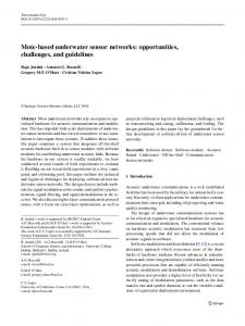
(a) Grand Canal
(c)
River Dodder
(b) Ranelagh Ponds
(d)
Fig. 1.5. Shape of S 4 symbol as received in (a) Indoor aerial channel; (b) River Dodder;(c) Grand Canal in Dublin; (d) Ranelagh pond.
Our field tests in different bodies of water have revealed a distinct background noise and interference pattern in each case. For instance, the primary noise source in swimming pools is water pumps, whereas the noise sources in a river include downstream currents and wildlife activity. The dependance of the noise profile on the deployment environment requires calibration steps, which could be manual or automatic, prior to placing
September 28, 2010
16
17:39
World Scientific Review Volume - 9in x 6in
software˙driven
R. Jurdak
the sensors in the water. Fortunately, the implementation of modulation and communication in software provides maximum flexibility for on-the-fly calibration. A central issue for calibration is the frequency-selective noise in the deployment environment. The choice of frequencies for the S 4 synchronization symbol must avoid frequencies with high noise in a particular deployment environment. The selection of the S 4 frequencies is critical for proper system operation, as choosing unsuitable frequencies causes large synchronization errors, resulting in many bit misalignments. Similarly, it is also important to choose data symbol frequencies that avoid the high noise frequencies. The selection of the suitable frequencies for S 4 synchronization and the data symbols can be done automatically. During an initial setup phase, one node, typically the base station, is designated as a calibration receiver, and another as a calibration transmitter. Upon deployment, the designated transmitter sends an apriori known calibration signal that includes a diverse set of S 4 symbols with different frequency combinations, followed by a sequence of frequency tones that covers all the possible symbol frequency tones. The designated receiver processes the calibration signal by comparing the processed signal against a locally stored version of the reference signal. The receiver then selects the frequencies that have been received with the highest SNR, and transmits a short broadcast message indicating these frequencies to the other nodes. Another calibration issue is ensuring that the stored reference S 4 symbol at each node is representative of the symbol as it is received in the current deployment environment. Our field experiments have shown that the structure of a received S 4 symbol with the Tmote Invent microphone in air is different than its structure in water. As Figure 1.5 shows, the structure even varies across different water bodies, depending on the current, depth, and suspended solids in the water. For instance, the envelope of the S 4 symbol differs significantly when the signal is received in the river (Figure 1.5(b)) and in the pond (Figure 1.5(d)). The plots in Figure 1.5 illustrate that the relative amplitude of each of the square signals changes depending on the medium. Other signal artifacts, such as impulses at the beginning or at the end of the signal, are also dependent on the deployment environment. As such, each node should store at least one instance of the S 4 symbol as it is received in the current deployment environment. This maximizes the probability of successful correlation and synchronization through the S 4 mechanism.
September 28, 2010
17:39
World Scientific Review Volume - 9in x 6in
Software-Driven Underwater Networks
software˙driven
17
1.4.3. Fouling Fouling is a process by which marine wildlife, such as barnacles, zebra mussels, weeds, and algae attach themselves to still object in the water. Avoiding fouling effects is especially important for software-driven underwater sensor networks since the attachment of organisms to the membrane could limit or change the membrane’s vibration characteristics. Traditional antifouling approaches include the use of special copper-based paints to prevent the attachment of organisms to boat bottoms. Current research focuses on developing alternatives23 to paint-based solutions, which are harmful to the ambient environment. Our project aims at protecting the environment, and not damaging it in the process, so we intend to adopt one of the emerging anti-fouling techniques. One interim solution under consideration is to place the nodes in the latex membranes and then to fix the membranes inside a resilient cubic plastic box whose purpose is to shield the nodes from fouling and other hazards in harsh underwater environments. The surfaces of the plastic box would be perforated to maintain acoustic coupling between the box contents and the water. 1.4.4. Deployment Software-driven underwater sensor networks target long-term monitoring applications, which demands suitable strategies for deployment, tracking network health and performing network maintenance when necessary. First, the deployment strategy must ensure that the nodes are well-anchored in the environment, so that tides, waves, and marine wildlife do not cause the nodes to move and lose connectivity with neighboring nodes. Anchoring methods are highly dependent on the deployment environment. In a river, nodes may be anchored either to the river floor through attachment to a heavy object, or to the river bank through suspension with a solid pole that is securely fixed to the river bank. In larger bodies of water, the former anchoring method is preferable since most points of interest will be far from the water edges. In addition to anchoring, deciding where to deploy sensor nodes is also highly dependent on the application scenario. In the river monitoring application, sensors can be placed at regular distance intervals all along the river. When monitoring water quality, sensor placement should take into account potential pollution sources in the river, such as pipes or construction sites that may dump pollutants into the water. In some instances,
September 28, 2010
17:39
18
World Scientific Review Volume - 9in x 6in
software˙driven
R. Jurdak
providing redundant sensors immediately upstream and downstream from the pollutant sources can prove crucial for delivering timely alerts to water management officials on pollution events, such as the dumping of waste material into the river. 1.5. Conclusion This chapter has introduced software-driven underwater acoustic sensor networks as an enabler of dense shallow water wireless network deployments. Building on our practical experience with underwater communication experiments in the River Dodder in Dublin, the discussion focused on river monitoring as a motivating application scenario for softwaredriven underwater sensor networks. The system components of softwaredriven acoustic networks were then presented, including the signal modulation, synchronization, filtering, and demodulation techniques for software modems. Looking ahead towards a full network stack based on software modems, the design of higher layer communication protocols for this system should also adopt a cross-layer design approach to minimize control overhead. Logistical considerations for underwater networks depend on the deployment environment. We have identified common logistical considerations low-power underwater networks, which include the need for resilient waterproofing and casing, calibration, deployment strategies, and anti-fouling measures. Our initial experiments in various bodies of water have exposed the benefits of using software modems for underwater communications capable of functioning on off-the-shelf multi-purpose sensor modules. The design guidelines in this chapter lay the groundwork for further development of software-driven underwater sensor networks. References 1. B. Sauser. “Networking the Hudson River,” Technology Review, Published by MIT. August, 2007. available: http://www.technologyreview.com/Infotech/19309/ 2. J. Cui, J. Kong, M. Gerla, and S. Zhou. “Challenges: Building Scalable Mobile Underwater Wireless Sensor Networks for Aquatic Applications,” IEEE Network, 20(3):12–18, 2006. 3. I. F. Akyildiz, D. Pompili and T. Melodia. “Underwater acoustic sensor networks: research challenges,” Ad Hoc Networks (Elsevier), vol. 3, no. 3, pp. 257-279, March 2005. 4. I. Vasilescu, K. Kotay, D. Rus, M. Dunbabin and P. Corke. “Data Collection,
September 28, 2010
17:39
World Scientific Review Volume - 9in x 6in
Software-Driven Underwater Networks
software˙driven
19
Storage, and Retrieval with an Underwater Sensor Network,” In Proc. Sensys’ 05, San Diego, CA, 2005. 5. J. Heidemann, Y. Li, A. Syed, J. Wills, and W. Ye. “Underwater Sensor Networking: Research Challenges and Potential Applications,” USC/ISI Tech. Rep. ISI-TR-2005-603, 2005. 6. X. Yang et al. Design of a Wireless Sensor Network for Longterm, In-Situ Monitoring of an Aqueous Environment. Sensors, 2:455-472, 2002. 7. Linkquest Inc. available at: www.link-quest.com 8. DSPComm. available at: www.dspcomm.com 9. R. A. Iltis, H. Lee et al. “An Underwater Acoustic Telemetry Modem for Eco-Sensing,” In proc. Oceans’05, September 2005. 10. Utility Acoustic Modem available at: auvlab.mit.edu 11. J. Wills, W. Ye, and J. Heidemann. “Low Power Acoustic Modem for Dense Underwater Sensor Networks,” In Proc. IEEE (WUWNet06), 2006. 12. C. V. Lopes and P. Aguiar. “Acoustic Modems for Ubiquitous Computing,” IEEE Pervasive Computing, 2003. 13. Blauert, Jens (Ed.) Communication Acoustics. Springer, 2005. 14. R. Jurdak, P. M. Q. Aguiar, C.V. Lopes, and P. Baldi. “A Comparative Analysis and Experimental Study on Wireless Aerial and Underwater Acoustic Communications,” Proceedings of the IEEE International Conference on Digital Telecommunications (ICDT). Cap Esterel, France. August, 2006. 15. R. Jurdak, C.V. Lopes, and P. Baldi. “Software Acoustic Modems for Short Range Mote-based Underwater Sensor Networks,” In Proc. of IEEE Oceans Singapore. May, 2006. 16. R. Jurdak, P.M.Q. Aguiar, P. Baldi, and C.V. Lopes. “Software Modems for Underwater Sensor Networks,” In proc. of Oceans.’07. June, 2007. 17. R. Jurdak, A.G. Ruzzelli, G.M.P. O’Hare, and C.V. Lopes. “Reliable Symbol Synchronization in Software-Driven Acoustic Networks,” In Proc. of IEEE GlobeCom Washington D.C. November, 2007. 18. Sentilla Corporation. available: www.sentilla.com 19. P. Harris, M. Stojanovic, and M. Zorzi. “When Underwater Acoustic Nodes Should Sleep With One Eye Open: Idle-time Power Management In Underwater Sensor Networks,” In Proc. WUWNet, 2006. 20. A.G. Ruzzelli, G.M.P O’Hare, and R. Jurdak, “Merlin: Cross-layer integration mac and routing for low duty-cycle sensor networks”, To appear on Elsevier Ad Hoc Networks Journal, Special Issue on Energy efficient design in wireless ad hoc and sensor networks, 2008. 21. R. Black. “Research Needed on Marine Sound,” BBC News article, available: news.bbc.co.uk/2/hi/science/nature/4706670.stm 22. R. Jurdak. Wireless Ad Hoc and Sensor Networks: A Cross-Layer Design Perspective. Springer-Verlag, 2007. 23. The Maya2 Project. http://www.maya-net.org/