Java-based Software Interlock System (SIS) was ... interlocks system the connections between client systems .... code related to subscription management.
Proceedings of ICALEPCS07, Knoxville, Tennessee, USA
WPPB03
SOFTWARE INTERLOCKS SYSTEM J. Wozniak, V. Baggiolini, D. Garcia Quintas, J. Wenninger, CERN, Geneva, Switzerland Abstract In the year 2006, a first operational version of a new Java-based Software Interlock System (SIS) was introduced to protect parts of the SPS (Super Proton Synchrotron) complex, mainly CNGS (CERN Neutrinos to Gran Sasso), TI8 (SPS transfer line), and for some areas of the SPS ring. The SIS protects the machine through surveillance and by analyzing the state of various key devices and dumping or inhibiting the beam if a potentially dangerous situation occurs. Being a part of the machine protection, it shall gradually replace the old SPS Software Interlock System (SSIS) and reach the final operational state targeting LHC (Large Hadron Collider) in 2008. The system, which was designed with the use of modern, state-of-the-art technologies, proved to be highly successful and very reliable from the very beginning of its existence. Its relatively simple and open architecture allows for fast and easy configuration and extension to meet the demanding requirements of the forthcoming LHC era.
CONCEPTS The energy stored in an SPS and LHC beam is orders of magnitude above the damage level of accelerator components like vacuum chambers, magnets, etc. For this reason both SPS and LHC must be protected by an interlock system, composed of a Beam Interlocks System (BIS) [1] and the Software Interlock System (SIS). The role of the BIS is to prevent injection and extraction or dump the beam whenever a failure may lead to a damage of accelerator components. It is entirely implemented in hardware and designed to fulfil extremely high safety and availability requirements. The SIS complements the BIS and provides further protection of the accelerator. It implements more complex logic, which can anticipate problems rather than merely reacting to them. This logic can be easily re-configured to respond to changing needs.
Basics of Hardware Interlocks A number of BIS users (also referred as clients) provide interlock signals (also referred to as permits) to the BIS. The permits are logical signals that may be TRUE (beam operation is allowed, no interlock) or FALSE (beam operation is not allowed, interlock present). The BIS applies an appropriate logic to the client signals and generates one or more output signals. The output signals are referred to as permit – they “permit” the beam to pass. The loss of the permit signal leads to a beam dump or to an injection or an extraction inhibit. For the hardware interlocks system the connections between client systems and the BIS as well as the connections to the kicker system consist of dedicated hardware links. The interlock logic is performed by appropriate hardware modules.
Software Interlocks The architecture of the Software Interlock System (SIS) does not differ fundamentally from the architecture of the BIS. The main differences arise from the fact that: • Signal or information transmission is not performed over dedicated hardware links but through standard software connections over Ethernet network. • The interlock logic is performed by software modules, both within the SIS and at the level of the client system. • The SIS is not a hard real-time system with hard time constraints. The delays amount to several seconds. The interest of an SIS system even for an accelerator that is protected by a hardware interlock system arises from a number of points: • The SIS is able to anticipate failures and prevent a beam from being ‘run’ (i.e. produced, injected or extracted from the injector). It allows a more efficient operation of the accelerator complex. • Complex interlock logic may be applied in the SIS, in particular correlation between different systems. • Software interlocks are very flexible and may be added or modified rapidly without need for cables or additional hardware. In the context of the CERN accelerator complex, the SIS provides permit signals to both the General Machine Timing System (GMT) and the BIS. The signals from the SIS provide the GMT with the appropriate information to stop or abort a given class of beams. An adequate reaction reduces the remnant radiation levels since the beams that are produced must otherwise be disposed of on a beam absorber or dump. At the same time the operation of the injectors may be optimized since a replacement beam may be operated instead of the interlocked beam. The connection to the BIS must be in the form of an input channel such that the SIS has the possibility to dump a beam and prevent further beams from being injected or extracted. In this way the software interlock channels of the SIS have a direct albeit slower connection to the BIS.
Individual Software Interlock Channels At a fundamental level a software interlock channel is associated to a measurement of a condition, a device state or property, a beam property, etc. The measured property is compared to a desired reference value, with the outcome that the measurement either matches the desired value (condition is TRUE) or not (condition is FALSE). Such a test is defined as an Individual Software Interlock Channel (ISIC). An ISIC is the basic building block of the SIS interlock logic. Each ISIC is associated with an accelerator equipment system and it constitutes the boundary between the monitored devices and the SIS. An ISIC may encapsulate a test of a single device or directly
Major Challenges
403
WPPB03
Proceedings of ICALEPCS07, Knoxville, Tennessee, USA
for a group of devices belonging to the same equipment system. The output signal of each ISIC is a logical signal that can be in one of two states: TRUE or FALSE. The ISIC is TRUE when the test is successful; it is FALSE when the test is not successful, either because the measured property is in an incorrect state or because no information from the device is available.
Logical Software Interlock Channels Several ISICs with some logical or geographic relationship can be grouped into so-called Logical Software Interlock Channels (LSIC). The state of an LSIC corresponds to the result of a logical operation applied on the state of all its ISICs. The logical operation may be an AND, an OR or a NOT operator. The state of each LSIC is either TRUE or FALSE.
the values of ISIC, LSIC and beam permits. One main architectural goal was to make the analysis part as reliable as possible and thus highly independent of the data acquisition: even if data acquisition fails, the analysis part continues to work reliably and cuts the beam if necessary. As for implementation, the SIS is implemented with standard controls components used in many other controls applications.
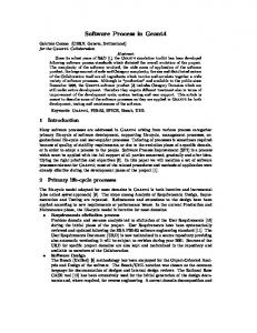
sis-core
Exporting permit
Timing event BIS
Alarms
Processing
Permit Signals Permit signals are top level LSICs which the SIS sends to the timing and hardware interlock systems. If the permit is false, the beam is inhibited and/or dumped.
?
data buffer japc-monitoring japc
Acquisition Subscription channels
Controls middleware Front-end A
Permit
Timing
Front-end B
Front-end C
Front-end D
Figure 2: High level architecture.
Data Acquisition Layer LSICs
ISICs Figure 1: Permit tree.
Interlock Masking Masking is a mechanism that allows operators to ignore an individual ISIC or LSIC. Masking a channel means overriding its real state and evaluating it always to TRUE. Because masking is a potentially dangerous intervention, an alarm is activated for each masked channel. The ability to mask a given ISIC/LSIC is defined for each channel individually. Permit signals are not allowed to be masked.
Interlock Latching Usually the states (TRUE or FALSE) of ISICs and LSICs change according to the equipment conditions, both for the transition from TRUE to FALSE and for the opposite transition. In certain cases, it is desirable to latch the FALSE state, so that the operator can examine the situation that caused the interlock. Latched interlock conditions must be manually unlatched from the user interface.
DESIGN AND ARCHITECTURE The SIS has a layered architecture, which reflects the two major tasks of the SIS – data acquisition and data processing. The data acquisition part collects data from all monitored devices and puts it into a data buffer. The data processing part analyzes the collected data by calculating Major Challenges
404
This layer acquires data from multiple sources (devices) using the subscription mechanism provided by the controls middleware (CMW) [2]. The most important component of the data acquisition layer is the japcmonitoring framework. It is a library built on top of JAPC (Java API for Parameter Control) [3] and CMW that provides a standard way to develop subscription-oriented 3-tier applications. Japc-monitoring allows developers to connect so called ‘client modules’ with business logic to JAPC subscriptions. The client modules just process updates – they do not have to deal with JAPC specific code related to subscription management. In the case of the SIS, the client module is a rolling data buffer from which data can be extracted and processed by the data processing layer explained in detail below. Japc-monitoring has the following main features: • JAPC parameters configuration management using XML files. • Automatic JAPC subscription handling (monitoring, restarting, etc.). • Alarms system connection (LASER) [4]. • A diagnostic GUI that visualizes the state of the subscriptions and the data values received.
Data Processing Layer This part analyzes the device data and calculates beam permits. As already mentioned, the interlock logic is defined as a boolean expression over the subscription channels (ISICs and LSICs) which is used to calculate the permit (it constitutes the permit). This expression can be represented as a tree. The SIS can have multiple trees corresponding e.g. to geographical locations in the SPS
Proceedings of ICALEPCS07, Knoxville, Tennessee, USA
ring and transfer lines. Tree processing starts with a timing event. Data belonging to a given tree is taken out of the data buffer (located in Data Acquisition Layer) and the boolean expression is calculated up the tree to create the permit value. This data processing is done once per cycle for each tree. The resulting permit values are exported to various external systems like BIS, GMT (timing), LASER (alarms) and possibly others.
Configuration with XML and Velocity Each of the two main layers is configured separately. The configuration is stored in XML files. The file for the data acquisition layer describes all devices (JAPC parameters) that have to be monitored. The file for the data processing layer defines the boolean expression trees for each permit composed of the number of individual and logical channels. Given the large number of channels (over a 1000) Velocity [5], a template language, is used to generate parts of the configuration on the fly, thus eliminating the need for large, static and verbose text files. XML inclusions help splitting the configuration into smaller, logically separated pieces. The configuration files are all kept in the versioning system (CVS) allowing for easy change and version maintenance.
Data Persistence The SIS has a transparent persistence layer that allows for storing the state of the system during restarts. It is used to maintain the information about all masked and latched channels. The persistence layer is designed to be transparent and fault resistant. It hides possible database access problems from the rest of the system and retries all database operations once the connection is restored.
Integration of Components in Spring All SIS layers and components are connected together with the use of the Spring framework [6]. All vital components are defined as Spring beans in an XML file and managed in a bean container by this framework. Solutions from Spring have been also applied to provide remote access to the SIS core service via a JMS channel.
Flexibility of Extensions The SIS core libraries and components are designed to be easily configurable and flexible. Extension points allow developers to provide their own implementation of components. They cover the areas of system configuration, data transformation, trigger events and exporters of the calculated boolean expression tree. Extension points are implemented using careful interface design and by leveraging the Spring Framework.
Graphical User Interface (GUI) As the SIS is a server side application, a GUI was developed to show the system state to the operators in the control room. All permit trees are visible and dynamically updated; channel states are expressed with colours. Operators can easily search the permit trees using multiple filtering criteria (e.g. to display only faulty
WPPB03
channels). The GUI allows also for some user actions like masking, unmasking or unlatching the channel(s). The GUI is connected to the SIS core via a JMS channel, and receives all kinds of update messages (tree evaluation, states, errors, etc) from the server asynchronously. When a permit evaluates to false and the beam is dumped, the operator wants to know why. The SIS provides a sophisticated analysis mechanism that searches through logging messages and is capable of identifying several typical fault scenarios, such as a missing data or a data with incorrect values. It also facilitates viewing parameter subscriptions’ states by integrating the diagnostic GUI of japc-monitoring.
Deployment The SIS project is split into several parts. The core (server) part constitutes a sis-core project. The GUI is located in a sis-gui project. Those two do not contain any proprietary configuration files related to any of CERN accelerators. The configuration part is extracted in another project, namely sps-sis (SIS for SPS) and contains configuration specific for SPS accelerator. This is the project that is actually released, deployed and run on the server machine. A separate backup machine exists to assure safety of operation. The GUI application is distributed in a form of a Java Web Start JNLP file that can be executed from any operators console in the control centre. A JMS broker needed to provide remote services is run on yet another machine.
CONCLUSIONS As of today the SIS successfully surveys over 1200 individual software channels for the SPS accelerator. It has become a vital tool for everyday operations and is ready to be extended to cover the LHC machine. The architecture described in this document has proven itself very reliable in practice making the SIS project a great success at CERN.
REFERENCES [1] R. Schmidt et al. “Beam Interlocks for LHC and SPS”, ICALEPCS’2003, Gyeongju, Korea. [2] K. Kostro et al., “Controls Middleware: the New Generation”, EPAC’02, La Villette, Paris, France, 3 7 Jun 2002, pp.2028. [3] V. Baggiolini et al., “JAPC - the Java API for Parameter Control”, ICALEPCS’2005, Geneva, Switzerland. [4] K. Sigerud et al., “First Operational Experience With Laser”, ICALEPCS’2005, Geneva, Switzerland. [5] http://velocity.apache.org [6] http://www.springframework.org
Major Challenges
405