allow us a rapid develop of the control system we have ... coming from the machine and a web tools to help the ... Application Development (RAD) software.
MOY01
Proceedings of PCaPAC08, Ljubljana, Slovenia
SPARC CONTROL SYSTEM OPERATION F. Anelli, M. Bellaveglia, E. Chiadroni, L. Cultrera, G. Di Pirro, D. Filippetto, S. Fioravanti, E. Pace, INFN LNF, Italy L. Catani, A. Cianchi, INFN Roma 2, Italy. Abstract We describe the control system operation for the new injector project built at the Laboratori Nazionali di Frascati INFN (SPARC [2]). The injector started the operation in the autumn of the 2007 and the control systems has been full operating since the start of commissioning and integrate all tools to help the machine operation. The SPARC control system must follow all evolution in the continuous machine installation and evolution. To allow us a rapid develop of the control system we have made some choices: Labview as developing system due to its diffusion in the laboratory and it because is standard in the acquisition software; Gigabit Ethernet as interconnection bus (in order to have sufficient bandwidth in the data exchange); PC as front-end CPU and operator console. We developed control applications for magnetic elements, vacuum equipments, RF cavities, all diagnostics, laser and some experimental apparatus have been developed and debugged on line. We developed an automatic process to store all information.
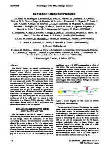
Figure 1: SPARC
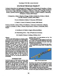
SPARC The SPARC (Sorgente Pulsata e Amplificata di Radiazione Coerente, Self-Amplified Pulsed Coherent Radiation Source) (fig.1) project is to promote an R&D activity oriented to the development of a high brightness photo injector to drive SASE-FEL experiments at 500 nm and higher harmonics generation. Proposed by the research institutions ENEA, INFN, CNR with collaboration of Universita` di Roma Tor Vergata and INFM-ST, it has been funded in 2003 by the Italian Government. The machine is installed at Laboratori Nazionali di Frascati (LNF-INFN). It is composed by an RF gun driven by a Ti:Sa laser to produce 10-ps flat top pulses on the photocathode, injecting into three SLAC accelerating and 6 udulator sections. The gun has been installed with a diagnostic apparatus called e-meter [5] (fig. 2). This apparatus allows us to characterize the first 2m of the electron beam. The main component, from the control system point of view, is the emettance measure apparatus composed by a pepper-pot Classical Topics
10
and a YAG target. This part of the e-meter can be moved in any position along a 2 m bellow. At the end is available a spectrometer to measure the energy and a toroid to read the bunch charge.
Figure 2: E-meter
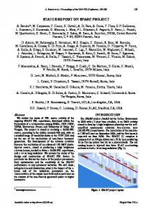
SYSTEM DESCRIPTION The control system should guarantee and simplify machine operation. In general the main operations in an accelerator control system are: • data taking • display of information • analysis • command execution • storage. The simplest and functional control system has distributed processors on a classic three levels architecture. • First level: at this level we find the console with its human interface to allow the operator to control the machine, a logbook to share information within the collaboration, a database to store all information coming from the machine and a web tools to help the management of the control system and to share some information outside the collaboration; • Second level at this level we find the front-end CPU that executes commands and handle all the information about the status of the machine available at the first level. Meanwhile it automatically saves data from its various elements in two ways: on value changes and/or at fixed time intervals; • Third level is the acquisition hardware where we find an appropriate acquisition board or the secondary field bus to acquire data from the real element. The interconnection bus between the levels is a Gigabit Ethernet LAN.
Hardware First of all we decided that each distributed CPU controls only a certain type of elements. This simplifies the Status Reports and Control System Overviews
Proceedings of PCaPAC08, Ljubljana, Slovenia
number and type of acquisition board assigned to the front-end processor. We want to use the right processor in depending on the element to control. We decide to implement in our system PXI bus, industrial personal computer and real time processors. At console level we need the maximum flexibility in terms of number of screens and possible remote connections. Also at this level, we plan to use small form factor PCs with at least 4 monitors each. A storage facility for the whole system software and data is foreseen.
Software In order to reduce the time of development of the SPARC control system, we decided to use well known Rapid Application Development (RAD) software. Labview became the natural choice for the following reasons: o in the collaboration laboratories the use of National Instrument software is very popular (we can say it is a “standard”); o Labview is used as development software in the DAFNE [3] control system. This choice allows us to re-use, when possible, already existing software; o Labview is considered as reference software by many hardware manufacturers that write interface drivers in Labview. Other software such as Matlab (whose integration with LabView is very well established), Mathematica or selfmade will be introduced and integrated in the control system in order to help the online and offline analysis of the beam during the machine operation.
MOY01
the laser apparatus. The main operation is the alignment of the light with the mirror, that can be controlled by means of a motor while the laser light is acquired through a video camera. Other parts can be controlled by means of standard interfaces such as Ethernet or serial.
RF The RF section includes controls for the high power and the low power apparatus. The modulator can be controlled with Ethernet or serial interface with an appropriate protocol. Signal monitoring and synchronization is designed using a demodulation board and digitizer cards in a PXI chassis, where data analysis and device control are accomplished. The signal apparatus can be seen as a custom multi-channel digital scope, able to display in the control room all the demodulated signals coming from the RF structures placed along the whole machine. Other devices such as attenuators, phase shifters, amplifiers and so on will be controlled with serial or Ethernet interfaces.
Magnet In the accelerator we have a lot of different kind of magnets such as solenoids, correctors, dipoles and quadrupoles. Magnet control means controlling their power supplies. We decided to use as much as possible the same interface between the control and the power supply The following specifications will be required to the power supply factory: Ethernet, RS232 or RS485 interface; the well defined communication protocol Modbus as standard interface protocol to the power supplies.
Vacuum The main components in the vacuum system are the thermoionic pump and vacuumeters. The interface between vacuum pump and control system is based on a fieldbus with anolog and digital channels. We found a solution based on Fieldpoint[3] bus from National Instrument. This hardware is easily integrated in our system. The vacuometer allows an accurate measure of the vacuum in some points of the machine. The interface used is a serial interface with a proprietary protocol.
Diagnostic Figure 3: Control System Structure
ELEMENTS During the machine commissioning we test and develop the necessary software.
Laser To allow the optimization of the laser on the cathode, its remote control is essential. In order to implement this we need to control the maximum possible components of Classical Topics
The main machine parameter emittance, bunch length and energy in SPARC are measured with images. The use of a versatile camera system is strategic in the realization of this diagnostic. The rapid evolution in the image acquisition systems allows us to choose the cameras and their own interfaces between in a wide variety of products. The IEEE1394 interface gives us the possibility to interface different cameras with different specifications. The saved images are used by offline beam analysis. The cameras are acquired by different distributed personal computers that send data trough a Status Reports and Control System Overviews
11
MOY01
Proceedings of PCaPAC08, Ljubljana, Slovenia
TCP/IP channel. We well defined the data transfer structure to full integrate the cameras inside the control system. Another important component in the diagnostic is the control of motors to move flags and slits to allow the acquisition of the beam image. Also for the e-meter we need to move position slits and flags. We have written some useful programs to acquire automatically the image to measure the emittance along the e-meter. That stress the control system during this measure we take 30 image each slit position, 13 slits position each z position, 30 z position for a total of 11700 image and round 450 motor movements each emitance evolution measure. The beam position and charge monitors are acquired in the system. The beam position monitor SPARC are made with the strip line. Their reading is done by using an electronic Bergorz (LR-BPM) to condition the signals and their reading is done using a system of CRIO National Instrument (real time system with FPGA on board). The charge is read in two ways: using a toroid or using a Faraday cup. In the first case we have a continuous reading during the accelerator operation while the second system is used when you have to acquire information more precisely. The toroid is read using an electronic conditioning Bergoz (BCM-HR) that is read using the National Instrument board NI PCI 4070 DIMM. The cup is faraday acquired directly using a National Instrument board NI PCI 5152 (2Gs/s Digitizer/Oscilloscope).
SERVICE PROGRAMS The SPARC collaboration involves different national and international research institutions. Some services are necessary to allow all people to have the information available on the status of the machine and the progress of the work. The old system based on a paper logbook where the operator writes the data and glues pictures on it can be useful but cannot be available from remote researchers. We choose to develop an electronic logbook based on PostgresSQL [11]. These choices allow us to costumaze and integrate it in the control system.
Classical Topics
12
Status log machine During the e-meter operation we start to study the possibility to have an automatic saving this mechanism can be useful in the mantence of the machine and in the offline analysis. So there is data acquisition system based on a database with a possibility to communicate via TCP/IP (PostgreSQL). In the first operation we have each front-end processor running programs that send periodically all data of the controlled elements to the database. We have developed some different interface programs that can correlate the information
ACKNOWLEDGEMENTS We want to thank Luis Antonio Rossi and Serena Strabioli for their contribution in the hardware installation. We are also grateful to all the SPARC staff for their continuous suggestions and encouragement for making a good and useful job.
REFERENCES [1] The SPARC project is financially supported by the EU Commission in the 6th FP, contract no. 011935 EUROFEL and contract no. RII3-CT-2003-506395 CARE. [2] SPARC Project Team, Sparc Injector TDR http://www.lnf.infn.it/acceleratori/sparc/ [3] G. Di Pirro et al., "DANTE: Control System for DAFNE based on Macintosh and LabView", Nuclear Instrument and Methods in Physics Research A 352 (1994) 455-475. [4] LabVIEW, National Instruments Corporation, 11500 N Mopac Expwy, Austin, TX 78759-3504 USA (http://www.ni.com) [5] A. Cianchi, et al., "Design Study of a Movable Emittance Meter Device for the SPARC Photoinjector", Proceedings of EPAC2004, 5-7 July, 2004 Lucerne, Switzerland
Status Reports and Control System Overviews