2009 Eigth IEEE/ACIS International Conference on Computer and Information Science
Software Reliability Assurance Using a Framework in Weapon System Development: A Case Study Dalju Lee1, Jongmoon Baik1, Ju-Hwan Shin2 Korea Advanced Institute of Science and Technology, 335 Gwahangno, Yuseong-gu, Daejeon, 305-731 Korea {dalju, jbaik}@kaist.ac.kr 2 Agency for Defense Development, P.O.Box 18, Chinhae, Kyungnam, 645-600 Korea
[email protected] 1
software size embedded in A7 was 10 KSLOC in the 1960s, recently developed aircrafts such as F-22 include software on a scale of 15,000 KSLOC for providing better avionics control and automatic data processing to the pilots [2]. Therefore, an increase of software proportion in embedded systems is a sign that it has become very important to implement and/or acquire high reliable software. On the other hand, the losses caused by unreliable software in weapon systems are more serious than in other industrial software. There are several cases of software failures. Iran Air Flight in 1998[3], Patriot Missile in 1991[4], and delayed development of F-22 [5] were all caused by software failures. While hardware failures are explained by analyzing physical properties (temperature, pressure, stress, and humidity) for each item in the systems, software failure is not independent of factors such as the software developers, software development process, and the developing environment for the system. Many researches [6][7] address directly that reliability goal setting and operational profile development should be performed at an early phase in the Software Development Life Cycle (SDLC) to build reliable software systems. Especially for weapon systems, it is very difficult to correct the faults once it is already at the mass-production phase or the operation phase. Therefore, it is highly recommended to consider activities not only testing stage but also the whole life cycle activities in order to guarantee high reliable software systems. Nevertheless, the reliability assurance efforts in Korean defense domain have focused only on hardware reliability based on a RAM (Reliability, Availability and Maintainability) guideline. Also, the study on software reliability assurance throughout the system development lifecycle has been recently initiated. The primary purpose of our research is to offer a
Abstract In embedded systems like weapon systems, the proportion of software has been growing and the quality of software, which provides complicated functionalities of a system and controls hardware, affects the quality of the entire system. Besides, to implement/acquire reliable software, we need the efforts for assuring process quality as well as product quality in the whole software development life cycle. In this paper, we propose a framework to assure software reliability of weapon systems in Korean defense domain. The framework provides a guideline for software reliability evaluation to software organizations and pursues the improvement of software engineering process which supports activities and indicators for quantitative project management in the software development process. We also present the empirical study of the application of the proposed framework and the analysis results on the effectiveness of the proposed framework.
Key Words- Software Quality Assurance, Software Reliability, Framework
Goal-Question-Metrics,
Reliability
1. Introduction Modern weapon systems are embedded systems which are combinations of software and hardware. The software in an embedded system supports complicated functions of the system and controls the hardware parts. Moreover, some parts that are mission-critical in weapon systems are implemented by software. In this sense, the quality of a weapon system is dependable on the quality of the software embedded in the system. According to the embedded systems market analysis published by VDC in 2006 [1], the proportion of software in embedded system is increasing over all industries. In the case of aircrafts, the software size has increased considerably for the past forty years. While the 978-0-7695-3641-5/09 $25.00 © 2009 IEEE DOI 10.1109/ICIS.2009.168
989
Authorized licensed use limited to: Korea Advanced Institute of Science and Technology. Downloaded on May 12,2010 at 00:52:52 UTC from IEEE Xplore. Restrictions apply.
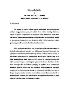
the stages of the framework. The activities in each stage are summarized in the Table 1.
software reliability assurance framework for weapon system developments in Korean defense domain. This paper is organized as follows. Section 2 introduces the proposed framework. Section 3 describes the empirical study and improvements elicited from data/reliability analyses. In Section 4, a validation of the proposed framework is provided with effectiveness analysis results. Finally, we describe conclusion and future works.
Table 1. Activities of Each Stage in Framework Stages Domain Analysis
2. Framework for Software Reliability Assurance in Weapon System Development
Establishme nt of Software Reliability Goal Metrics Identificatio n related to Software Reliability Data Collection Data Analysis
In this section, we describe the framework we developed for SRA (Software Reliability Assurance) for weapon system developments. The framework consists of 7 stages as shown in Figure 1.
Evaluation of Software Reliability
Figure 1. Framework for Software Reliability Assurance of Weapon Systems Application of Improvements
Activities A1. Draw up a functional profile A2. Identify the needs of software reliability A3. Define the fault/failure type and the fault/failure severity A4. Understand a software development process A5. Understand a software development environment B1. Make trade-off analysis between software reliability and software development characteristics B2. Establish the quantitative level of software reliability C1. Conduct a survey of software metrics C2. Identify software reliability metrics C3. Establish templates for software reliability metrics D1. Establish a data collection plan D2. Collect data through templates E1. Analyze collected data through software reliability metrics E2. Analyze artifacts in software development process E3. Elicit improvements F1. Draw up an operational profile F2. Allocate software reliability goal F3. Predict software reliability through software prediction models F4. Estimate software reliability through software estimation models F5. Elicit improvements G1. Review improvements G2. Establish a device for software reliability improvement
3. Application of the Framework for SRA This section describes the empirical study using we performed for a software company (Software Company K) where the proposed framework was applied.
3.1. Domain Analysis Domain analysis was performed to acquire the knowledge of the weapon system and the development process. In order to make an analysis of the current situation, we reviewed the company’s system development process and business guides, fault management process & configuration management process, and hardware reliability assessment process through RAM guidelines. We also collected the
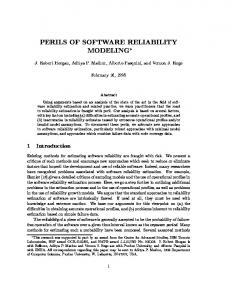
Figure 2. Mapping between Software Development Process and Stages in the Framework The each stage in the framework for SRA is preformed simultaneously with a software development process as shown in the Figure 2. It shows the mapping between software development process phases and the activities in 990
Authorized licensed use limited to: Korea Advanced Institute of Science and Technology. Downloaded on May 12,2010 at 00:52:52 UTC from IEEE Xplore. Restrictions apply.
information on real stakeholders, organizational structure, system construction, development schedule, and artifacts to get better understanding on the weapon system developed by the company K.
Table 2. Selected Metrics for Weapon System Metrics for requirements tracking y Requirement change ratio y Requirement Traceability Metrics of complexity y Cyclomatic Complexity y Halstead Software Science metrics
3.2. Establishment of Software Reliability Goal This stage has not been performed because the software reliability needs from the customer doesn’t exist and the studies on software reliability are still in its infancy. However, we used the GQM (Goal Question Metric) approach, in order to set a goal, “Reliable Weapon System Development”, for the project and to identify the necessary metrics for the reliability evaluation.
Metrics of Inspection and review y Defect Density y Man hours per major defect detected y Defect removal efficiency y Defect distribution Metrics of testing y Fault Density y Man hours per major fault detected y Fault removal efficiency y Cumulative fault profile y Test coverage y Fault distribution Metrics of Reliability Growth Models y Failure rate y Remained/Expected failure count y Reliability y Failure intensity
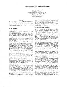
3.2. Metrics Identification related to Software Reliability We performed research on related standards, related researches, and related books for the framework. IEEE 982.1 [8] and 982.2 [9] standard provide 39 measures classified into product and process categories and those measures mapped for each SDLC stages. Li’ and Smidts’s research [10] introduces top ranked software reliability metrics based on experts’ opinion. H. Kan’s book [11] provides metrics and models in the practice of quality engineering in SDLC. Based on the research, we summarized 54 metrics. Software metrics for SRA suited to weapon systems are selected by using the GQM approach, one of the well-known ways to define metrics. Figure 3 shows the metrics identification by using the GQM approach. Each question is used to select metrics from the set of the summarized metrics. The subset of the selected metrics is shown in Table 2.
All over SDLC
Design and Implementation phase Early phase in SDLC ( before testing ) Testing
Testing
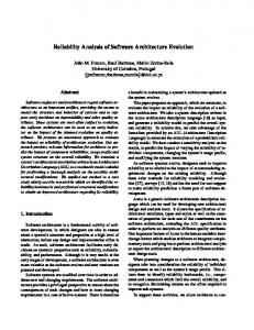
3.4. Data Analysis In the previous section, eighteen metrics were selected through the GQM approach. The four metrics, (list four metrics), among them are used for software reliability evaluation. Other metrics are used for the data analysis. Firstly, requirement change ratio and requirement traceability are used to check how well the requirements can be traced to the latter phases during the development life cycle. Software Company K showed high requirement change ratio at the design phases, such as PDR (Preliminary Design Review) and CDR (Critical Design Review), because of additional requirements from customers as shown in Figure 4.
3.3. Data Collection We collected the historical data of A-weapon system developed by a software company (Software Company K), which is one of MND (Ministry of National Defense) contract companies, with the templates we created for data collection.
Figure 4. Requirement Change Ratio in SDLC At an early stage, a high change ratio does not have a large impact on the project but at latter phases, the high change ratio can be a huge potential risk causing problems such as schedule and budget overruns Requirement traceability is used to assess whether there are missing requirements from the original set of requirements. Software Company K uses automated tools like DOORs [18] for requirement management throughout the life cycle. Secondly, complexity metrics are provided as the quantitative judgment criteria for minimizing defects in the design and implementation phases. Software company
Figure 3. Metrics Identification based on GQM 991
Authorized licensed use limited to: Korea Advanced Institute of Science and Technology. Downloaded on May 12,2010 at 00:52:52 UTC from IEEE Xplore. Restrictions apply.
y
K had easily obtained the complexity metrics using the automated testing tool, LDRA [17], at the implementation phase. Figure 5 shows the comparison of size and complexity for three different CSCIs (Computer Software Configuration Items). The complexity of B-CSCI is not proportional to the size that indicates the modularity of BCSCI is much higher than others. The weapon system is composed of multiple CSCIs, each of which has several CSUs (Computer Software Units). Each CSCI is implemented independently from separate development teams.
Man hours per major defect detected is represented as the average hour to detect one defect and is used to evaluate the efficiency of the inspection activities. The values are shown in Figure 7. On the average, Software Company K spent about 1.35 hours to detect a major defect in the review process. However, there were some missing data values for preparation effort and rework effort in the reports created from the formal reviews. Therefore, it was impossible to accurately estimate the effectiveness of the formal review activities at the company.
Figure 7. Man Hours per Major Defect Detected in Formal Review Finally, testing metrics such as fault density, man hours per major fault detected, fault removal efficiency, fault distribution, cumulative fault profile, and test coverage, were used to analyze the effectiveness of the validation activities. The results from the analyses are described as follows:
Figure 5. Source Size and Cyclomatic Complexity by CSCIs
y
Thirdly, to examinine the effectiveness of inspection and review activities at Software Company K, we conducted the analyses with pre-identified metrics such as defect density, man hours per major defect detected, defect distribution and defect removal efficiency. The analysis results are as the following: y
y
Software Company K does not have inspection process for the early stages in SDLC. Instead, they use a formal review process for the verification of the artifacts. No formal review was performed for the artifacts produced from the design and implementation phases. Therefore, it was very difficult to analyze all the defects detected in the early stages. For the analysis on defect removal efficiency, the percentage of defects removed during each phase was not studied. Figure 6 represents the trend of defects density for requirement specifications.
According to the results of fault distribution, fault type and fault severity level are converged at a few factors; Even if Software Company K defines the defect type and severity level at the organizational level. Many developers have problems in clearly understanding the criteria of the classifications. Figure 8 shows the distribution of the fault type. B, E, and C-type are top-ranked; the rate of them occupy 84% over all the faults (B-type: 37%, E-type: 27%, C-type: 20%).
Figure 8. Fault Distribution by Type The testing phase at the Software Company K reflects the characteristics of weapon system developments in defense domain. Each phase is properly defined for the embedded system development and test environments. Most of testing efforts are focused on FAT (Factory Acceptance Test) phase where the integrated system with hardware and software systems is tested. Figure 9 represents the fault density on different testing phases. The vertical axis indicates the degree of fault density at
Figure 6. Defect Density on SRS Evolutions 992
Authorized licensed use limited to: Korea Advanced Institute of Science and Technology. Downloaded on May 12,2010 at 00:52:52 UTC from IEEE Xplore. Restrictions apply.
each testing phase; the horizontal axis illustrates testing phases, QT (Quality Test), FAT (Factory Acceptance Test), DT (Development Test), and OT (Operational Test).
Third, we put through the prediction based on COQUALMO. It predicts the number of remaining defects based on input parameters. For the analysis, we set PMAT(Process Maturity) driver as “Very High”, which reflects CMMI level 4 for Software Company K. The analysis results based on COQUALMO were compared to the actual defect density at end of implementation phase of Software Company K. Figure 12 shows the results.
Figure 12. Results from COQUALMO
Figure 9. Fault Density by Testing Phase y
Man hours per major fault detected is represented as the average hour to detect one major fault. Figure 10 shows the average hours to detect a major fault, about 15 hours. However, some of the records have missing data on some fields. Thus, it is hard to analyze the fault removal efficiency.
3.5.2 Software Reliability Estimation Software reliability estimation of the weapon system is accomplished by using the CASRE Tool. CASRE [16] is a well-known and widely-used tool in the field of software reliability estimation. Experienced failure data are the fault counts in each of the testing intervals and interval length is one month; they are collected for 19 months and are not classified by their severity. Figure 13 shows failure density, f(t); hazard rate, h(t); reliability, R(t); and unreliability F(t) calculated from the collected failure data set.
Figure 10. Man Hours per Major Fault Detected in Testing Phases
3.5. Evaluation of Software Reliability 3.5.1 Software Reliability Prediction We performed the analysis with three different reliability prediction methods, an application of industry data [13], Musa Prediction Method [14], and prediction based on COQUALMO (COnstructive QUALity MOdel)[15]. First, software reliability prediction is gauged by the industry data which describes typical defect potentials and delivered defects at different SEI CMM levels. The average potential defect density for a SEI CMM level 4 organizations is 0.038 defects/KSLOC. The defect density at the end of implementation phase shows that the weapon system development has three times higher defect density than the industry average. Second, we carried out Musa Prediction Method. For the estimation of reliability using the Musa model, we had to decide the initial failures for the system. Initial failure rate is calculated by following figure 11.
Figure 13. Software Failure Density, Hazard Rate, Reliability, and Unreliability The experienced failure data set was analyzed by interval domain models, which are Generalized Poisson model, NHPP based interval model, Scheidewind model, and Yamada S-Shaped model, in the CASRE and SchickWolverton model was not applied. In addition, the weighted value, “alpha” factor, was assigned as 1.0 for Generalized poisson model to apply to the test interval lengths; Cutoff S value, which represents a point changed testing environment, was assigned as 6 for Schneidewind model; and Parameter estimation method was used for Maximum Likelihood Estimation that is the default method in the CASRE. Figure 14 shows the failure intensity distribution that calculated by differentiating the mean-value function.
Figure 11. Results from Musa Method
993
Authorized licensed use limited to: Korea Advanced Institute of Science and Technology. Downloaded on May 12,2010 at 00:52:52 UTC from IEEE Xplore. Restrictions apply.
reliable weapon systems, it is necessary for all the stakeholders to understand and recognize the software reliability concept and importance. Namely, a top-down support from the enterprise level and bottom-up training from the engineering level must be harmonized within the organization.
4. Validation This section discusses the validation of the framework as the effectiveness of the framework is shown by the comparison between the two weapon systems. To validate, this paper use the experiment data which is collected from two-weapon systems developed by Software Company K. Data set 1 is the data collected from the software requirements analysis stage to the preliminary design stage of A-weapon system. Data set 2 is the data collected during the same period for B-weapon system. We tried to prove that the framework contributes to decreasing the number of defects at earlier stages. Therefore, we had the one hypothesis that decreasing the number of defects at earlier stages goes along with the application of the framework.
Figure 14. Failure Intensity Distribution Goodness-of-fit test helps to determine how closely the model results fit to the actual failure data. In the empirical analysis we performed, the Chi-Square statistic verification was used because failure data set is interval based. However, we could not find any well-fitted model from the analysis.
3.6. Application of Improvements This section presents improvements elicited from the data/reliability analyses. These can be used to improve software development process for Software Company K. In addition, they are suggested for reliable weapon system development to Software Company K. The identified improvements are as the followings: • Software Company K has a configuration management process with CCB (Configuration Control Board) but omissions of items in the artifacts created throughout the SDLC must be discovered. • Software Company K is a CMMI level 4 organization; however, quantitative indicators focused on the business management and general quality factors. Hence, additional baselines in terms of software reliability must be established within the organization. The selected matrices must be used to define the baselines. y Software Company K does not have clear criteria for the classifications of defect/fault type and severity. For systematic classification of items, they should be introduced with a fault categorization technique, like ODC (Orthogonal Defect Classification) [19]. y Time data is the most important to reliability analysis. However, Software Company K does not recognize the importance of software reliability analysis. As a result, we redefined data collection sheet and suggest a use of an automated tracking system for defect data collection and tracking. y Software Company K have to minimize requirement changes after software requirement analysis stage
- A null hypothesis (H0): There is no difference in the number of defects decreased at earlier stages before and after the application of the framework. - An alternative hypothesis (H1): There is a difference in the number of defects decreased at earlier stages before and after the application of the framework. To validate the hypothesis, we experimented with data set 1 of A-weapon system and data set 2 of B-weapon system by using the MINITAB tool. We used a statistical method that is a two sample t-test with confidence interval of 95%. Figure 15 shows the result of two-sample T-test of C1 and C2. - C1: defect density of A-weapon system without application of the framework. - C2: defect density of B-weapon system with application of the framework.
Figure 15. Result of Two-Sample T-Test The result from the t-test shows that the P-value (0.000) is smaller than the significance level (0.05). Therefore, the null hypothesis is rejected and the alternative hypothesis is adopted. Consequently, there is a difference in the number of defects decreased at the earlier stages before and after the application of the
The main business of Software Company K is the development of weapon systems and they already have the knowledge of hardware reliability. To develop high 994
Authorized licensed use limited to: Korea Advanced Institute of Science and Technology. Downloaded on May 12,2010 at 00:52:52 UTC from IEEE Xplore. Restrictions apply.
framework. The mean value of A-weapon (C1) system is 1.2. On the contrary, the mean value of B-weapon system (C2) is 0.4. Furthermore, defect density in B-weapon system with application of the framework shows 66% more reduction than A-weapon without application of the framework. We also analyzed the trend of defect density between the two systems. The trend of the defect density in Bweapon system is more stable than the one in A-weapon system as shown in Figure 16.
7. References [1] VDC(2006), The Embedded Software Market Intelligence Program. [2] Rick Barbour, "CMMI: The DoD Perspective", SEI Presentation, Oct. 2006 [3] "Formal Investigation into the Circumstances Surrounding the Downing of Iran Air Flight 655 on 3 July 1988", Investigation Report, U.S. DoD, 19 Aug. 1988. [4] "Software Problem Led to System Failure at Dhahran, Saudi Arabia", US GAO, Feb. 4, 1992. [5] Government Accountability Office, "Tactical Aircraft, F/A22 and JSF Acquisition Plans and Implications for Tactical Aircraft Modernization, Statement of Michael Sullivan, Director, Acquisition and Sourcing Management Issues," GAO-05-519T, April 6, 2005. [6] J. Musa, "Software Reliability Engineering: More Reliable Software Faster and Cheaper", 2nd edition, Authorhouse, 2004. [7] R. Lyu, "Handbook of Software Reliability Engineering", IEEE Computer Society Press, 1997.
Figure 16. Trend of Defect Density between Two Systems
[8] IEEE Std 982.1-1998, "IEEE Standard Dictionary of Measure to Produce Reliable Software", IEEE Standards Board, 1998.
5. Conclusion & Future Work
[9] IEEE Std 982.2-1998, "IEEE Guide for the Use of IEEE Standard Dictionary of Measures to Produce Reliable Software", IEEE Standards Board, 1998.
This paper introduced the framework for weapon systems in Korean defense domain. The framework for SRA consists of 7 stages to assure software reliability of weapon systems. We provided systematic guidelines for software reliability evaluation, efficient data collection and data analysis, and the metrics associated with software reliability in the defense domain. To show application of the framework, we performed a reliability analysis with the collected experience data set from Software Company K. The analysis results can be reflected for the improvement of software development process. Furthermore, we validated the effectiveness of the framework by comparing the analysis results from the two weapon systems: one with application of the framework and one without. The weapon system with the framework applied showed the improvement in software quality. For our future work, we will attempt to offer a methodology on how to conjunct software reliability and hardware reliability in Korean defense domain. This is because the entire system reliability assurance comes from the combination of hardware reliability assurance and software reliability assurance.
[10] M. Li and C. Smidts, "Ranking Software Engineering Measures Related to Reliability Using Expert Opinion", Proceedings of ISSRE, p. 246 – 258, San Jose, California, 8-11 October, 2000. [11] H. Kan, "Metrics and Models in Software Quality Engineering", Addison-Wesley, Second Edition, 2003. [12] V.R. Basili, "Software Modeling and Measurement: The Goal Question Metric Paradigm," Computer Science Technical Report Series, CS-TR-2956 (UMIACS-TR-92-96), University of Maryland, College Park, MD, September 1992. [13] C. Jones, “Measuring Global Software Quality”, Software Productivity Research, Burlington, MA, 1995. [14] B. Peter, L. Neufelder, A. M. Neufelder, "System and Software Reliability Assurance Notebook", Rome Laboratory. [15] B. W. Boehm, at el., “Software cost estimation with COCOMO Ⅱ”, Prentice Hall, 2000. [16] Allen P. Nikora, "Computer Aided Software Reliability Estimation: User's Guide, version 3.0", Jet Propulsion Lab., March 2000. [17] LDRA Tool, Automated testing tool, http://www.ldra.com. [18] Telelogic DOORs, Requirement management tool, http://www.telelogic.com/Products/doors/doors/index.cfm.
6. Acknowledgement
[19] R. Chillarege, at el., "Orthogonal Defect classification-a cencept for in-process measurements", IEEE Transactions on Software Engineering, 18(11):943-956, 1992.
This work was supported by the Korea Research Foundation Grant funded by the Korean Government (KRF-2008-313-D00932) 995
Authorized licensed use limited to: Korea Advanced Institute of Science and Technology. Downloaded on May 12,2010 at 00:52:52 UTC from IEEE Xplore. Restrictions apply.