resources, thus allowing the belter design of altematives. Some of the ...... Sharpley, A. N.; William J. R EPIC Model Documentation USDA Tech. Bull No 1768 ...
Simulation is the process of building models and analyzing the system. ... Crop
models are tools of systems research which help in solving problems related to ...
validation and verification phases. Correcting the data of- ten requires additional data collection and there may be no. âquick fixâ to this kind of problem.
optimisation algorithms. Simulation based optimization is an available feature in most COTS simulation software. However, in these software different search ...
Jerome of Northwestern University, Drs. Ke-chih Wu and Lydia. L. So of Stanford ..... has held summer staff position at Fairchild, Bell Telephone. Laboratories ...
Even this small list shows various levels of expected knowledge. On the web site .... The idea of a character simulation is to immerse the learner in a social experi- ence in which a ... including Flash, wave, and graphic files. Run a pilot to gather
mated raw data collection and automated processing of raw data to simulation ... For example, the Overall Equipment Efficiency (OEE) is often found to be.
Jan 23, 2007 - reaction time's probability density function (PDF). In the case of an elementary ...... Input files and scripts are provided in the appendix [§7].
According to Tarski, a model is a vehicle that can be used to ... programs. Furthermore, related empirical models are proposed. Successful ...... Montreal, Canada. ..... Mechanical, historical, philosophical or psychoanalytical explanations for ...
Rome NY 13441-4505. 10. SPONSOR/MONITOR'S ACRONYM(S). N/A. 11. SPONSORING/MONITORING. AGENCY REPORT NUMBER .... List of Acronyms .
Nov 23, 2011 - the model to produce data which are similar to that collected from the ...... routines are established (and broken). Living ... tive targets such as laptop computers, multimedia ...... an offender's hard drive and notified police. The.
sometimes becomes certified or accredited which is an. "official" detennination that a model .... PROBLEM. ENTITY. COMPUTERIZED COMPUTER PROGRAMMING ..... Design and Verification of Simulation Programs,. Computer, Vol. 10, No.4 ...
The trade-off between catch of productive commercial species ...... sawsharks (Pristiophoridae), angel sharks (Squatinidae), school sharks (Galeorhinus ..... observing juvenile fish, although the meta-analyses of Myers et al. ...... (5.7) Ft = qcEfft
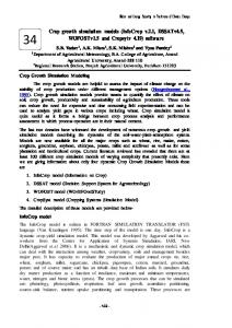
Water and Energy Security in The Arena of Climate Change. - 456 -. Crop growth simulation models (InfoCrop v.2.1, DSSATv4.5,. WOFOSTv1.5 and Cropsytv ...
âVerification and Validation of Simulation Models.â In Proc. 2005 Winter Simula- tion Conf., edited by M. E. Kuhl, N. M. Steiger, F. B. Armstrong, and J. A. Joines, ...
Ascape. Our Solution. (Boxed Economy). Supporting Systems for. Agent-Based Simulation. Figure 1: Level of Abstraction, Languages, and. Supporting Systems.
Model Driven Development of Agent-Based Simulations. Takashi Iba â 1 ... become serious too much up to now, because ...... 59â68 (IOS Press). [Kleppe et al.
totally for other years (Fig.2) which highlights the limitations of descriptive models. .... System which is essentially a computer software to match crop requirements to .... a very effective scientific tool for tailor-made introduction of new produ
call malloc at each time-step compared to the actual operations performed .... in Proceedings of the 2nd Conference on Modeling and Simulation for. Safety and ...
each component in the library becomes a basic building block (module) to ..... Microsoft's Visual Basic that lets a programmer request access to a Microsoft ...
tion of a real robot's API (application programmer ... ment kit (SDK) for EyeSim is identical to the RoBIOS operating system for the real EyeBot robots, including a.
validate and fine tune operating plans and account for the unit's hardware constraints ... simulation model developer to easily create (without any Visual Basic ...
also tested our approach by using a fictitious call center. We observed that this approach increases the accuracy of a metamodel and decreases the sum of ...
gravel of the stream bed and the porous areas near the stream bank. ... equations may be solved for both dynamic (time-varying) and steady-state condi- tions. .... MHMS (paper presented AWRA Annual Conf., Reno, Nevada, November 1992).
Juan M. Pestana. University of California, Berkeley. PEER 2001 Annual Meeting. Oakland, California. January 26, 2001. RESEARCH SUPPORTED BY THE ...
SOIL-STRUCTURE-INTERACTION SIMULATION MODELS Juan M. Pestana University of California, Berkeley
PEER 2001 Annual Meeting Oakland, California. January 26, 2001 RESEARCH SUPPORTED BY THE PACIFIC EARTHQUAKE ENGINEERING RESEARCH CENTER IN COLLABORATION WITH THE CALIFORNIA DEPARTMENT OF TRANSPORTATION AND THE NATIONAL SCIENCE FOUNDATION
SEISMIC SSI- CONCLUSIONS • Key components are: (foundation) soil, foundation system & structure. • Key issue of Performance Based Design is the evaluation (estimation) of performance -> Requirement of robust, efficient & realistic numerical- analytical description of material response & system. • Development & refinement of laboratory experiments which can accurately represent the problem are essential to validate “individual” constructs (numerical/conceptual blocks). It therefore provides an invaluable resource for calibrating numerical Codes-> Reduce inherent modeling uncertainty. • Successful development of coupled site response and Soil-PileSuperstructure Interaction analyses provides a Comprehensive framework for Performance Based Design for increasingly higher shaking levels
Structural Engineer ’s Engineer’s View of the World
Geotechnical Engineer ’s Engineer’s View of the World
Courtesy of Dr. Lehman- University of Washington
SOIL-STRUCTURE INTERACTION • Types of structures (buildings, bridges, bunkers) • Transfer Function: Empirically or analytical description of the behavior of a structure given response at ground level. • Estimation of performance – Shallow foundations- A lot of work still needed (i.e., mat foundation). A lot of interest - effect of structure embedment. – Deep Foundations- A lot of interest- Highway/ retrofit of Bridges and other structures in soft soilsSSI is extremely important.
SSI- DEEP FOUNDATIONS Soil-Pile-Superstructure Interaction Coupled Model
Modal Mass
Overall Response
Earthquake Motion input time history
Seismic Soil- Pile GroupStructure Interaction Test
Near field element: partitioned dynamic nonlinear p-y/t-z spring = f(strain rate, #cycles, strain reversals) Far field element: radiation damping = f(soil nonlinearity in near and free field)
input time history
Free field element: time domain site response inputs motions at nodes
k1
k2
k3
c1
c2
c3
NONLINEAR SITE RESPONSE ANALYSES- MODEL Modulus Degradation for Clay ( Vucetic & Dobry) 1 G/Gmax
model
0.5 (Vucetic & Dobry)
0 -4 10 30
-2
10 Damping for Clay (Vucetic & Dobry)
Damping Ratio (%)
• KEY ELEMENTS: • ABILITY TO MODEL SMALL STRAIN NON-LINEARITY AND DAMPING CHARACTERISTICS • FLEXIBILITY TO REALISTICALLY DESCRIBE RESPONSE FROM SMALL TO LARGE STRAINS • CORRESPONDENCE WITH MEASURED SOIL BEHAVIOR - ESTABLISHED PARAMETER DETERMINATION • CHARACTERIZATION OF UNCERTAINTY
10
0
model
(Vucetic & Dobry)
20 10 0 -4 10
-2
10 Shear Strain (%)
10
0
TEST SERIES 1.1 CROSSSECTION
SPECTRAL ACCELERATION input time history
5% Damped Spectral Acceleration (g
Modal Mass
5% Damped Spectral Acceleration (g)
NONLINEAR SITE RESPONSE ANALYSIS CALIBRATED with VERTICAL ARRAY INFORMATION
2
Elev 0
0 2
Elev -8
0 2
Elev -18
0 2
Elev -30
0 2
Elev -48
0
0
0.01
0.1
1
Period (sec)
10
Nonlinear element Gap element
Pile
Far field
Friction element
gap element
nonlinear element
1.0
+
y gap
=
-1.0 -1.0
y/yc
p/pult
pgap /pult
p-y element
p/pult
1.0
1.0
-1.0 -1.0
1.0
y/yc
+ y/yc
1.0
friction element
1.0
pfriction /pult
-1.0 -1.0
-1.0 -1.0
y/yc
1.0
1.0
Formulation of nonlinear 1-D element
NUMERICAL CAPABILITIES -NONLINEAR py, t-z springs with Gapping Capabilities 1
p-y curve for clay p-y w/ gap (loop 1)
p/pu
p-y w/ gap (loop 2)
0.5
0 -8
-6
-4
-2
0
2
4
gap -0.5
-1
y/yc
6
Pile
8
8
NEAR FIELD RESPONSE
depth = 5d
depth = 6d
depth = 7d
depth = 8d
depth = 9d
0
Soil Resistance P (lb/in)
Modal Mass
depth = 4d
-8 8
0
-8 8
0
Calculated Test Data
input time history
-8 -0.5
0
Deflection Y (in)
0.5
-0.5
0
Deflection Y (in)
0.5
D
FOUNDATION RESPONSE- BENDING MOMENTS
S2
S3 ft)
input time history
S4
0 1 2 3 4 5 6
Depth (ft)
0 1 2 3 4 5 6
S3
0 1 2 3 4 5 6
Depth (ft)
Depth (ft)
S1
Depth (ft)
Modal Mass
0 1 2 3 4 5 6
0
0.5 Bending Moment (k-in)
1
PSA (g)
PREDICTION OF STRUCTURAL RESPONSE 5
S1
4
PSA (g)
PSA (g)
4 3
3
2
2
1
1
0 5
0 S2
5
3
4
PSA (g)
4 2
PSA(g)
1 0
S4
PSA (g)
Modal Mass
S3
5
3 2 1
PSA (g)
PSA (g)
0
input time history
0.01
0.1 1 Period (sec)
10
Computed Max. Sa (g)
5
STRUCTURAL RESPONSE
4 3
1 0
1.6
0.8
S1
S2
S4
0.4 0 0
Computed Tp (sec)
Computed Max. Sa (g)
(a)
0.4 0.8 1.2 1.6 Recorded amax (g)
2
Computed Tp (sec)
Computed amax (g)
2
S3
S3 S4
2
0
(b)
1.2
S2 S1
1 2 3 4 Recorded Max. Sa (g)
5
0.3 S4
0.2
S3
S1 S2
0.1
5
0 (c)
0
0.1 0.2 Recorded Tp (sec)
0.3
Spectral Accelerat ion (g)
Performance of Pile Groups Equivalent Pier Approach
Response of Structure
3.0 Damping=5%
Recorded e=1.0 e=0.8
2.0
e=0.6 e=0.4 e=0.2
1.0 1
0.0
Response of Pile Cap Damping=5%
0.6
p-y efficiency
3.0
Spectral Accelerat ion (g)
2x2 pile gr 3x3 pile gr
0.8
Recorded
0.4
e=1.0 e=0.8
2.0
e=0.6 e=0.4
0.2
e=0.2
1.0 0 0
0.2
0.4
0.6 Input MHA
0.0 0.01
0.1
1
Period (sec.)
10
0.8
1
Multidirectional Shaking 2-D & 3-D Site Response Analyses r u 0.08 S
Pacoima Dam record a = 0.05g
l 0.06 e l l 0.04 a r a 0.02 P
max
50 m Soil Profile
t 0.00 l u a-0.02 F -0.04
-0.06 -0.06
-0.04
-0.02
0.00
0.02
0.04
Fault Normal Surface Motion (m)
0.06
0.08
) rL 10.0 o. F d .u d 5.0 e z i sl 0.0 (a /m P r -5.0 o ,N e -10.0 c) rL 10.0 o. F d
Test B1D3 L/D= 2 w (Hz) 3.0 Symbol A/d 5% 10 % 20 % 50 % API
-0.4
-0.2
0
0.2
0.4
Normalized Deflection, y/d Test B3D4 L/D= 8 w (Hz) 3.0
.u d 5.0 e z i l 0.0 a m r -5.0 o N -10.0
Symbol A/d 5% 10 % 20 % 50 % API
-0.4
-0.2
0
0.2
Normalized Deflection, y/d
0.4
MULTIDIRECTIONAL P-Y ELEMENTS
Numerical Tool * Nonlinear Site
OpenSees Platform
Response (2-D) * Near Field, p-y New Elements
Near Field, t-z and Q-z Capabilities
CONCLUSIONS- DEJA VU • Key components are: (foundation) soil, foundation system & structure. • Key issue of Performance Based Design is the evaluation (estimation) of performance -> Requirement of robust, efficient & realistic numerical- analytical description of material response & system. • Development & refinement of laboratory experiments which can accurately represent the problem are essential to validate “individual” constructs (numerical/conceptual blocks). It therefore provides an invaluable resource for calibrating numerical Codes-> Reduce inherent modeling uncertainty. • Successful development of coupled site response and Soil-PileSuperstructure Interaction analyses provides a Comprehensive framework for Performance Based Design for increasingly higher shaking levels