A slotted solid iron rotor machine, a copper coated solid iron rotor and a squirrel cage rotor machine. In a first step two dimensional finite element models.
Solid Rotor Induction Machine Optimisation based on Finite Element Techniques K. TATIS, A. KLADAS and J.TEGOPOULOS Faculty of Electrical and Computer Engineering National Technical University of Athens 9 Iroon Polytechneiou str., 15780 Zografou, Athens GREECE
Abstract: - An optimisation procedure for solid rotor induction machines, exhibiting important advantages for braking operation due to the simplicity of their construction, is presented. Both non-salient and salient rotor structures have been considered and compared. Design optimisation has been performed based on the finite element method combined with sensitivity analysis techniques. The developed techniques have been applied to optimise braking capability in case of permanent magnet generator coupling. Key-Words: - Finite elements, eddy current brake, sensitivity analysis, induction machine in order to obtain a simple structure only solid rotor machine configurations have been considered. The design of the brake as well as the evaluation of the equivalent circuit parameters can be obtained by using finite element techniques [2],[3]. However, the optimization of the rotor geometry may require laborious and expensive numerical schemes especially when 3D configuration should be considered [4],[5]. Although both stochastic and deterministic optimization algorithms can be implemented [7]-[9], the sensitivity analysis technique combined with finite element methods enables robust and fast convergence [1].
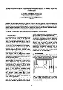
1 Introduction An important problem of variable speed generating units such as wind turbines is the over-speed protection in cases of abrupt increase of the input power. The use mechanic brake presents important deficiencies namely large and not well-controlled time constants, excessive mechanical stresses etc. In this work an auxiliary eddy current brake is introduced mounted on the same axis with the generator. As the generator considered is a permanent magnet synchronous machine, braking action can be applied equally in cases of disconnection from the grid (Fig. 1). Three different types of asynchronous machine structures have been considered. A slotted solid iron rotor machine, a copper coated solid iron rotor and a squirrel cage rotor machine. In a first step two dimensional finite element models have been used in conjunction with a sensitivity analysis technique in order to optimise the rotor geometry with respect to the braking performance. In a second step the parameters of the optimal structures have been calculated by the field analysis and the dynamic braking of the system has been studied, by using appropriate equivalent circuits. This work is related to a project concerning the design and construction of a 25 kW grid connected, stall regulated, variable speed wind turbine, equipped with a permanent magnet (PM) generator. The PM generator has already been optimized and tested through a prototype [1]. In order to enable braking operation the number of poles of the induction machine brake must be greater than the one of the PM generator. Moreover,
2 Methodology The geometry optimization of the eddy current brake is based on solid rotor configuration for construction simplicity purposes. The analysis problem has been
PM Generator
EC Brake
Dump Load
Fig. 1. Configuration of the wind turbine electric part in case of grid disconnection due to fault (PM generator supplying the eddy current brake and the resistive dump load).
1
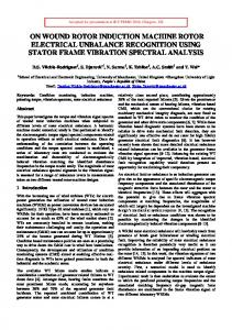
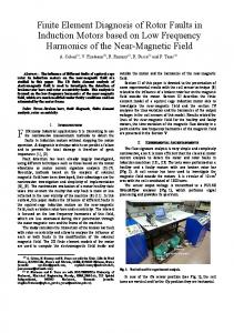
3 Results and Discussion One pole of the machine has been modeled. The main dimensions are given in the Table 1. Figure 2 shows the machine structure in the case of a copper coated solid iron rotor. The slotted stator cases have been considered by using the 3D FEM model for both copper and iron solid rotors. The respective field distributions for a frequency of 50 Hz are shown in Figs. 3a and 3b, respectively.
Fig. 2. One pole of the eddy current brake
solved either by using existing solutions of closed form (case of rotating field around non-salient rotor) or by 2D and 3D finite elements (slotted stator and rotor case). A particular reduced scalar potential formulation necessitating no source field calculation has been adopted to develop the 3D finite element model [11]. The analysis methods are developed hereafter. In the FEM model the rotor rotation has been considered by appropriate changes in the stator currents frequency f 1 corresponding to the rotating magnetic field. Moreover the source voltage amplitude Vm was modified in order to maintain constant the ratio Vm ω .
3.1 Numerical calculation of the torque The calculation of the developed torque is based on the following relation:
T=
P 3I 22 r2 (1 − s ) / s Ploss r = = ωm ω s (1 − s ) s ωs
(1)
where P is the internal mechanic power, Ploss r denotes the rotor losses, s the slip and ω s the synchronous rotating speed. The power losses of the rotor are provided by the numerical solution.
a
b
Fig. 3. Eddy currents distribution in the solid rotor induction machine, calculated by the 3D FEM model.
2
a: Copper rotor b: Iron roror
max min
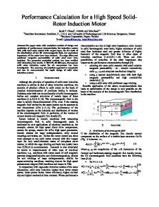
In Fig. 4 are given the torque variations with the normalized speed n n s calculated by the numerical model, for the solid iron rotor machine for three copper layers. Figures 5 and 6 show the same results for the slotted iron rotor machine and of the squirrel cage rotor machine structures.
Table 1 Dimensions of the eddy current brake Outer radius of the stator lamination 175 mm Inner radius of the stator lamination 125 mm Slot area of the stator 149,4 mm2 Radius of the rotor lamination 124 mm Radius of the shaft 74 mm Pole angle 15º
3.2 Evaluation of the equivalent circuit parameters
16
Torque (N.m)
14
The leakage and magnetizing inductances can be computed from the corresponding magnetic fluxes. These fluxes are calculated by using relation (2) in where the appropriate values of the vector potential are provided by the numerical solution.
12 10 8 6 4 2
∫
0
0,2
0,4
0,6
0,8
1
S
0,5 mm 1mm 1,5 mm
n/ns
S
∫
(2)
C
Resistance r2 is calculated by the computed rotor losses and the corresponding current. In tables 2 and 3 are shown the values of the equivalent circuit parameters for the two types of machines considered, that is the solid iron rotor machine with 1mm copper coating and the squirrel cage rotor machine.
Fig. 4. Torque of solid iron rotor machine for three copper coat widths
7 6 Torque (N.m)
∫
Φ = B ⋅ ds = rotA ⋅ ds ⇒ Φ = A ⋅ dl
0
5
Table 2 Equivalent circuit parameters of the solid iron rotor machine with copper coating thickness of 1mm
4 3 2 1
Parameter r1 r2 Lls Llr Lm
0 0
0,2
0,4
0,6
0,8
n/ns
1 10 mm 20 mm
Fig. 5. Torque of the slotted iron rotor machine
Value 2,872 Ω 3,6 Ω 8,45 mH 0,159 mH 9,895 mH
9 8
Table 3 Parameters of the equivalent circuit of the squirrel cage rotor machine
Torque (N.m)
7 6 5 4 3 2 1 0 0
0,2
0,4
n/ns
0,6
0,8
1
Fig. 6. Torque of the squirrel cage rotor machine
3
Parameter
Value
r1 r2 Lls Llr Lm
2,872 Ω 0,8 Ω 8,183 mH 3,431 mH 16,021 mH
3.3
The equation of the rotor rotation is as follows:
Dynamic braking analysis
The dynamic braking analysis has been simulated by using Matlab/Simulink software. Both cases of braking of the permanent magnet machine by using dump loads and the parallel operation of the permanent magnet machine with the eddy current brake have been considered. The initial; conditions correspond to a nominal pre-fault generator operation and sudden post fault mechanical rotor increase. In case of parallel operation of the two machines supplying the dump load connection of appropriate capacitors is also necessary to provide the reactive power absorbed by the eddy current brake. Moreover, the number of poles of the asynchronous brake must be higher than the one of the permanent magnet generator, in order to ensure generating operation for all rotor speeds.
dω rm = Tmech + Tem pm + Tem am − T friction (11) dt These equations use standard variable definition [12]. In Fig. 4 may be observed that the asynchronous brake with copper coated solid iron rotor develops higher torque at lower speeds. On the other hand, the squirrel cage rotor brake produces maximum torque at a slip of approximately 0.1, as illustrated in Fig. 6. That is why the considered copper coated solid iron rotor machine has 48 poles while the squirrel cage rotor one 26 for the permanent magnet machine with 24 poles. The best braking behavior has been obtained for a copper coating of 1 mm, as shown in Fig. 4. The parameter values of the permanent magnet machine are tabulated in the table 4.
2.1.1 Dynamic equations The dynamic equations of the permanent magnet machine in the rotor’s two axes (qd0) reference frame are: dλ q
(
Parameter
)
(3)
dλ d r = V d + ω r λ q + s (λ md − λ d ) dt Lld
(4)
r = Vq − ω r λ d + s λ mq − λ q dt Llq
Tem pm = 3 ⋅
Pole pm 4
⋅ (λ d iq − λ q i d )
Table 4 Parameters of the permanent magnet machine
The dynamic equations of the induction machine in the stationary reference frame are dλ qs dt dλ qr dt
= Vqs +
rs (λ mq − λ qs ) Lls
= ω r λ dr +
r pr L plr
(λ
mq
− λ qr
(8)
r pr dλ dr (λ md − λ dr ) = −ω r λ qr + dt L plr
(9)
Tem am = 3 ⋅
(
Poleam ⋅ λ ds i qs − λ qs i ds 4
)
Lld Lmq
13,911 mH 16,04 mH 9,47 mH 0 0 0,4192 Wb 3,42 kgm2
The braking capability for different system configurations has been examined. Initial conditions involve nominal wind turbine operation connected to the electrical grid. Then a sudden change in turbine torque has been considered with simultaneous grid disconnection and braking operation by using dump loads (operated at 10 sec in the following figures). In a first step the isolated operation of permanent magnet machine has been considered having a torque margin of 50% of the nominal torque. The braking characteristics of torque time variations are shown in Fig. 7 while the respective rotor speed time variations are given in Fig. 8. In a second step the parallel operation of permanent magnet machine with a copper coated solid iron
(7)
dλ ds r = Vds + s (λ md − λ ds ) dt Lls
2,872 Ω 13,928 mH
Inertia
(6)
)
rs Llq
Lmd Ln Rn Flux per pole, λ fd
(5)
Value
(10)
4
rotor machine has been considered providing a torque step of 300% of the nominal torque. The braking characteristics of torque time variations are shown in Fig. 9 while the respective rotor speed time variations are given in Fig. 10. Finally, the parallel operation of permanent magnet machine with a squirrel cage rotor machine has been considered providing a torque step of 300% of the nominal torque. The braking characteristics of torque time variations are shown in Fig. 9 while the respective rotor speed time variations are given in Fig. 10. These figures illustrate that auxiliary eddy current brakes can practically double the permanent magnet machine braking characteristics. However, appropriate capacitors are necessary (three capacitors of 500 μF in the cases considered) to provide the reactive torque absorbed by the induction machines. Moreover, the a copper coated solid iron rotor brake
provides practical rotor stall within 15 seconds while the squirrel cage rotor brake ensures a final speed approximately half of the nominal one within a few seconds. 150
T orque in N m
100
50
0
-50
-100
-150
0
5
10
15 20 Tim e in s ec onds
25
30
Fig. 9. Mechanical and electromagnetic torque time variations for the parallel operation of the permanent machine with the copper coated solid iron rotor brake.
100 Tm Tpm
80
Tm Tam Tpm
500
60 450 400 20 350 0
Speed in rpm
T orque in N m
40
-20 -40
300 250 200
-60 150 -80 100 -100
0
5
10
15 20 Tim e in s ec onds
25
30
50 0
Fig. 7. Mechanical and electromagnetic torque time Variations for the isolated operation of the permanent machine.
0
5
10
15 Time in seconds
20
25
30
Fig. 10. Speed time variation for the case shown in Fig.9. Tm Ta m Tp m
150
500 450
100
T o rq u e in N m
400
Speed in rpm
350 300 250
50
0
-5 0
200 -1 0 0
150 100
-1 5 0 0
50 0
0
5
10
15 Time in seconds
20
25
5
10
15 20 Tim e in s e c o n d s
25
30
Fig. 11. Mechanical and electromagnetic torque time variations for the parallel operation of the permanent machine with the squirrel cage rotor brake.
30
Fig. 8. Speed time variation for the case shown in Fig.7.
5
[5] S. B. Yoon , I. S. Jung, D. S. Hyun, J. P. Hong, Y. J. Kim, “Robust shape optimization of electromechanical devices”, IEEE Transactions on Magnetics, vol. 35, no 3, pp. 1710-3, 1999. [6] S. Ratnajeevan, H. Hoole, "Artificial neural networks in the solution of inverse electromagnetic field problems", IEEE Transactions on Magnetics, vol. 29, no. 2, pp. 1931-1934, 1993. [7] O.A. Mohammed, F.G. Uler, S. Russenchuk, M. Kasper, "Design optimization of a superferric octupole using various evolutionary and deterministic techniques", IEEE Transactions on Magnetics, vol. 33, no. 2, pp. 1816 -1821, 1997. [8] T. Higuchi, J. Oyama, E. Yamada, E. Chiricozzi, F. Parasiliti and M. Villani, “Optimization procedure of surface permanent magnet synchronous motors”, IEEE Transactions on Magnetics, Vol. 33, no 2, pp. 1943-6, 1997. [9] G. Preda, B. Cranganu-Cretu, F.I. Hantila, O. Mihalache, Z. Chen, K. Miya, "Nonlinear FEM-BEM Formulation and model free inversion procedure for reconstruction of cracks using pulse eddy currents", IEEE Trans. on Magnetics, Vol. 38, no 2, pp. 1241-1244, 2002. [10]A. Kladas, J. Tegopoulos, "3D eddy currents modeling by means of a particular reduced scalar potential technique", IEEE Transactions on Magnetics, vol. 33, no. 2, pp. 1350 -1353, 1997. [11]D. Rodger, N. Atkinson, "Finite element method for 3D eddy current flow in thin conducting sheets", IEE Proceedings, vol. 135, Pt A, no. 6, pp. 369-374, 1988. [12] C. Ong, "Dynamic simulation of electric machinery", Prentice Hall PTR, 1998.
500 450 400 350 Sp 300 ee d 250 in rp 200 m 150 100 50 0 0
5
10
15 20 Time in seconds
25
30
Fig. 12. Speed time variation for the case shown in Fig.11.
4 Conclusion A geometry optimization methodology based on finite elements combined to sensitivity analysis technique has been presented. This method has been applied to optimize the rotor geometry of a solid rotor eddy current brake used as over-speed protection in a permanent magnet generator wind turbine. Appropriate brake configurations involving simple construction enable to double the permanent magnet generator braking torque by using convenient capacitors and resistive dump loads.
References: [1] G. Tsekouras , S. Kiartzis , A. Kladas , J. Tegopoulos, "Neural network approach compared to sensitivity analysis based on finite element technique for optimization of permanent magnet generators", IEEE Trans. on Magnetics, Vol. 37, no 5/1, pp. 3618-3621, 2001. [2] A. Yahioui, F. Bouillault, "2D and 3D numerical computation of electrical parameters of an induction motor", IEEE Transactions on Magnetics, vol. 30, no. 5, pp. 3690-3692, 1994. [3] P. Dziwniel, F. Piriou, J.P. Ducreux and P. Thomas, “A time-stepped 2D-3D Finite Element Method for Induction Motors with skewed slots modeling”, IEEE Transactions on Magnetics, Vol. 35, no 3, pp. 1262-1265, 1999. [4] P. Di Barba, A. Kladas, P. Neittaanmaki, M. Rudnicki, A. Savini, “Application of global optimization strategies to the shape design of a Advances in transformer winding”, Engineering Software, No 19, Elsevier Science Ltd, pp. 121-125, 1994.
6