Nozzle throat area. â Factor in the burning rate (St. Robert's) law câ. â Characteristic speed. D. â Diameter. F. â Thrust i. K. â Burning surface to grain port area ...
3
Scientific Technical Review, 2014,Vol.64,No.2,pp.3-13 UDK: 621.454/66.621.453/.457 COSATI: 21-09, 21-08
Solving an Irregular Burning Problem in a Small Rocket Motor Nikola Gligorijević1) Mohammed Amine Boulahlib2) Saša Živković1) Sredoje Subotić1) Stevan Kozomara1) Momčilo Nikolić1) During the design and development of a solid rocket motor, intensive irregular burning appeared in the area of high initial temperatures. The cylindrical propellant grain was designed for approximately neutral burning, with a hollow tube and both burning ends as well as with the outer surface inhibited. A simple grain configuration and a propellant with plateau burning were selected, and the operating pressure of the rocket motor was chosen to be in the area of the plateau. Unfortunately, the special conditions of the gas flow through the propellant grain port, caused by the central tube passing through the grain channel, as well as high propellant temperature sensitivity, led to an increased turbulence and a very strong irregular burning occurrence at high temperatures (+50oC). In these conditions the combustion went out of the plateau regime and the pressure exponent rapidly grew up. The problem was solved without changing the double-based propellant composition. The high burning surface to nozzle throat area ratio was decreased below the critical threshold appearance of irregular burning, without significantly affecting the motor performances. The rocket motor nozzle and the propellant grain were redesigned. Despite the limited possibilities of changing the propellant grain geometry, an uncommon solution was found, opening a part of the inhibitor at the outer surface of the grain. Key words: solid rocket propellant, double-based propellant, propellant grain, erosive burning, surface burning, pressure coefficient, thrust.
Nomenklature Ab Aport
– Burning surface
F Ip
– –
Grain channel port area Nozzle throat area Factor in the burning rate (St. Robert’s) law Characteristic speed Diameter Thrust Burning surface to grain port area ratio (Pobedonoscev ratio) Effective burning surface to grain port ratio Burning surface to nozzle throat area ratio, Effective burning surface/nozzle throat area Thrust Pressure integral
I tot L n p , pc r T teff x w
– – – – – – – – – –
Total impulse Length Pressure exponent Pressure, Average pressure Burning rate Temperature Effective burning time Web burned Web burned Propellant density
At , Athroat c∗ D F Ki K i1 K n , K n1
ρp
– – – – – – – – –
Introduction
F
OR the use in the antitank guided rocket “Bumbar” (Figures 1 and 2), the Rocket Propulsion Department of the MTI - Military Technical Institute http://www.vti.mod.gov.rs/, designed a sustainer rocket motor with a double based, simply shaped propellant grain (Fig.3).
Figure 1. Antitank rocket “Bumbar”
Figure 2. “Bumbar”, axial cross section 1) 2)
Military Technical Institute (VTI), Ratka Resanovića 1, 11132 Belgradе, SERBIА University of Defense, Military Academy, Generala Pavla Jurišića Šturma 33, 11000 Belgradе, SERBIА
4
GLIGORIJEVIĆ,N. etc.: SOLVING AN IRREGULAR BURNING PROBLEM IN A SMALL ROCKET MOTOR
The propellant grain (Fig.3) is designed as an internal burning tube with unrestricted ends [1, 2]. The outer cylindrical surface of the grain is inhibited.
+ 50 0C
140
+ 35 0C
Thrust, F (daN)
120 100 80
+ 20 0C
60 40
- 30 0C
20 0
0
1
2
3
4
5
6
7
Time, t (s)
Figure3. Propellant grain
Figure 6. Thrust vs. time distributions
A small length to diameter ratio (L/D≈1.3) is supposed to provide a mildly progressive-digressive burning surface curve, with a high degree of neutrality (Fig.4).
In comparison with the mean values of pressure and thrust at ambient temperature (+20oC), it was expected for the mean values at high temperature (+50oC) to grow up slightly, in accordance with the temperature sensitivity of the propellant. Proportionally, it was also expected for the effective burning time to reduce, so that the pressure integral and total impulse remain approximately unchanged. Unfortunately, the pressure and thrust curves increased extremely, during the most period of the motor work. If the shapes of the pressure-time or thrust-time curves were analysed at +50oC, it could be seen that the pressure was extremely increased for most of the burning time, but near the end of burning, it decreased and entered the normal mode, just before the final pressure drop. The same phenomenon, but less visible, could be recognized even in the diagrams at the initial temperature +35oC. This rocket motor was not designed for such high pressure values because they could affect the proper operation of the thrust vector control (TVC) system [8]. This unexpectedly high pressure rise at +50oC could be defined as irregular burning, without an explanation of the real cause of the irregularity. On the basis of data from literature and recommended criteria for evaluating the combustion process, it is not easy to treat this phenomenon as erosive burning. But generally speaking, it might be possible to use the term "erosive burning" for any increase in the burning rate above the expected values. This phenomenon might be also interpreted differently, assuming that the expected burning law at +50oC went out the area of the plateau, with sharply increased pressure exponent due to the propellant temperature sensitivity. The smallest error in the definition of the phenomenon is made if it is termed as "irregular burning". However, any positive treatment can be planned only if the parameters describing the limits of this phenomenon are defined. Regardless of the confusion about the real nature of this phenomenon, if we try to describe the enormous pressure blow up in the rocket motor by more commonly known parameters that describe erosive burning, we can ask the question: what are the possible reasons for its occurrence, and what can be done to eliminate these reasons? High temperature may directly affect the increased intensity of the erosive burning ratio [3,4]. Moreover, when a solid rocket propellant is characterized by high temperature sensitivity, the pressure blow up at high temperatures leads to an increase of the pressure exponent (n) in the Saint Roberts burning law, and thus to the further increased burning rate. Double based propellants are more susceptible to the erosive burning than composite propellants [3].
500
Burning surface, Ab (cm2)
450 400 350 300 250 200 150 100 50 0 0,0
0,5
1,0
1,5
2,0
2,5
3,0
3,5
4,0
4,5
Web burned, x (cm)
Figure 4. Burning surface geometric distribution
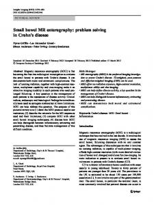
Theoretically, in a rocket motor, there is a clear correlation between the pressure (pc) in the combustion chamber and the burning surface (Ab) [1-4]. Therefore, it was expected for the shapes of the pressure-time and thrusttime curves to be very similar to the shape of the burning surface curve, with a mild parabolic form, close to the neutral, in a manner similar to those in Fig.4. The initial static tests of the grain in an experimental rocket motor, in the required temperature range (-30oC to +50oC), have not been fully successful, because irregular, probably erosive burning [3-7], appeared at higher temperatures (Figures 5 and 6). 140
+ 50 0C + 35 0C
Pressure, p (bar)
120 100
+ 20 0C
80
- 30 0C
60 40 20 0
0
1
2
3
4
5
6
7
Time, t (s)
Figure 5. Pressure curves at different test temperatures
The pressure and thrust-time traces at standard temperature (+20oC) were of the expected form and essentially very similar to the burning surface curve (Fig.4). The differences due to the temperature sensitivity of double based propellant that occured at the lowest temperature in the range (-30oC) were expected and their level was acceptable.
5
GLIGORIJEVIĆ,N. etc.: SOLVING AN IRREGULAR BURNING PROBLEM IN A SMALL ROCKET MOTOR
3. These include a potential increase in heat transfer from the gas flow to the burning surface. This heat flux passes through the combustion zone, providing additional heating and bending the diffusion flame towards the propellant surface [12], thus moving the point of heat release closer to the surface and increasing the burning rate. 4. It was found that the full-scale rocket motor has an unfavorable ratio of the burning surface to the nozzle throat area (coefficient K n = Ab / At ). This ratio is declared in literature as one of the criteria for the erosive burning appearance, but a possible range of the critical values of Kn is wide (100-1000) [3]. The critical (limit) value depends on a propellant type and its composition [3]. In our case, for the selected doublebased propellant, the critical value for the Kn is evaluated during the burning rate measurements, and it was similar to the value in the real motor. What was the procedure for the critical values evaluation of the factor Kn, for the given propellant composition? The propellant burning rate was determined using small ballistic evaluation motors (BEM) [9], with FLS internalexternal burning tubes, which produce a rather neutral pressuretime distribution. In our practice, these small test motors are called FLS (Fig.8), as well as their propellant grains.
Figure 8. Small (BEM) ballistic evaluation motor - FLS
Φ 32
The dimensions of the FLS grain are shown in the Fig.9.
Φ 16
The probability of erosive burning occurrence is greater in small rocket motors [3, 7] and in propellants with lower burning rates [3, 4, 7, 9]. The sustainer motor for the antitank rocket “Bumbar” can be treated as a small motor [1]. The burning rate of the double based propellant used in this motor is less than 9 mm/s at the standard ambient temperature. This burning rate is relatively small, but not too small [1, 3]. The erosive burning may also become troublesome in the motors with a low port to throat area ratio [5, 9]. Despite the fact that in the considered rocket motor both pressure and thrust diagrams were extremely bad at high temperature, there was an impression that the two abovementioned reasons are not strong enough to cause the erosive burning. Moreover, the erosive burning was quite unexpected for the following reasons: 1. The erosive burning usually occurs at the end of the long grain channel due to the large amount of flowing gases produced in the channel. At the end of the channel, these gaseous products of combustion have a high velocity parallel to the burning surface, which results in the increase of the burning rate in this area. 2. In the case of the considered motor, the length to diameter ratio for the grain is very small (L/D≅1.3) and it should not affect the increase of the burning rate. For instance, as a rule of thumb, the port to throat area ratio (Aport/Athroat) should be a minimum two, for a typical grain L/D ratio of six [10, 11]. The tested grain was quite short with the ratio Aport/Athroat >5. 3. Erosive burning may be caused by configuration complexity. Due to its simplicity, the solid propellant hollow-cylindrical grain is the least susceptible of all configurations to the erosive burning [2]. Generally, the criteria for erosive burning in the literature are not defined for all situations. Each specific rocket motor is different, so the various limits and boundary criteria are applicable in different situations. For example, “in certain grain designs, gas dynamic effects cause the effective port to throat area ratio to be less than geometric value” [2]. There were two possibilities for the occurrence of erosive burning: 1. Due to design reasons, the central tube passes through the grain channel reducing its cross section (Fig.7).
L = 125 Figure 9. FLS propellant grain
Figure 7. The rocket motor intersection, the propellant grain and the central tube
2. The gaseous products of combustion pass through the annular cross-section, between the outer surface of the central tube and the inner surface of propellant grain channel. The real value of the passage is significantly reduced, because it is effectively less than the geometric cross-section area, and the gas flow speed through the channel is highly increased.
In each test, a new, identical FLS propellant grain was used, but the dimensions of the nozzle throat were changed, thereby achieving the various mean pressure values. Usually, the burning rate evaluation tests are made at three different temperatures. One of them is the standard ambient temperature, +20oC, the other two temperatures are the limits of the range of rocket missile use, in this case -30 and +50oC. At each temperature the measurements at 8-10 different pressure values are done, which means that the tests are conducted by approximately ten different nozzles, thereby changing the values of Kn. The line that defines the linear combustion law (St. Robert's law) [1-4], changes its own slope when the value of pressure increases sufficiently.
6
GLIGORIJEVIĆ,N. etc.: SOLVING AN IRREGULAR BURNING PROBLEM IN A SMALL ROCKET MOTOR
When the slope (the pressure exponent) begins to increase, the value of Kn can be treated as critical for the tested propellant at the considered temperature. The Kn values change with temperature because the propellant is temperature sensitive. By increasing temperature, the critical values of Kn decrease. It means that there is a higher possibility of uncontrolled pressure rise and erosive burning occurrence at higher temperatures. A number of similar double-based compositions have been tested with the purpose of eliminating the irregular burning, but the propellant composition was not substantially changed. A typical diagram with the results of burning rate measurements at three characteristic temperatures (+50, +20 and -30oC) is shown in Fig.10. 14 13 0
+50 C
Burning rate, r (mm/s)
12 11
0
+20 C
10
445
9
0
504
8
-30 C
7
KN = 605
6 5
50
60
70
80
90
100
110
120
130
140
Pressure, p (bar)
Figure 10. Burning rate vs. pressure
During the rocket motor design, for initial calculations, the burning law at standard temperature is usually used. For the considered double-base propellant (middle curve in Fig.10) the burning rate curve consists of three distinctive parts. In the pressure range between 65 and 90 bar, which is ideally suited for the normal rocket motor mode, the pressure exponent (n) is low, resembling the plateau burning. This plateau is even better seen in the curves that correspond to extreme operating temperatures of +50 and -30oC. At the standard ambient temperature of +20oC, the Saint Robert's law is of the form: r = 3.14 ⋅ p 0.22 (mm/s)
(1)
p(bar ) - pressure
Fig.10 shows that the critical (minimum) value of the coefficient Kn for the chosen propellant is Kn =445, at the upper limit temperature of +50oC. This value may be treated as the limit for a potential occurrence of new conditions under a different burning rate law. In these new conditions irregular, perhaps erosive burning could occur. It is necessary to realize the motor design with the Kn value which is lower than the critical value for the propellant. In the case of the initial grain design (Fig.3), with the burning surface distribution as in Fig.4, and two nozzles with the throat diameter of 7.5 mm, the values of the coefficient Kn in the first phase of burning are greater than the critical one, in the range between 450 and 500, decreasing at the end of the process to the value of 340. The motor burning mode is designed to be in the range of pressures which is covered by the plateau regime of propellant combustion. Outside the range of the plateau (65÷90, or 60÷85 bar), the pressure exponent may grow up rapidly. In this case, the combustion law changes and exits the plateau.
If the operating pressure of the rocket motor falls below the lower limit value of the plateau, e.g. at low temperatures, it could also cause a type of unstable burning. Therefore, the rocket motor operating mode is designed to be in the area of higher pressures in the plateau range of combustion. This mode could be achieved if the burning surface distribution was approximately neutral, and the temperature sensitivity of the propellant was not too high. There is also a possibility for the operating pressure to go outside the plateau towards higher pressures. This case could occur at higher temperatures, due to propellant temperature sensitivity. In the diagrams of the burning rate vs. pressure for three different characteristic temperatures (Fig.10), the limit values of the factor Kn for each temperature are listed at the points where the pressure exponents rapidly begin to grow up and exit from the plateau. The limit values of the factor Kn (Fig.10) differ due to initial operating temperatures of the propellant and decrease inversely to the temperature. For the chosen propellant, if the initial temperatures are lower than approximately +30oC, these values are higher than the values of Kn in the full-scale rocket motor. In this case, the rocket motor works properly. In Figures 5 and 6 it is seen that in real motor there is no occurrence of irregular burning below +30oC. From the previous discussion it can be seen that two types of values for the factor Kn can be defined. The first characteristic value is the limit value that the propellant can withstand before the pressure exponent begins to increase, causing undesirable mode of combustion. The second value depends on the full-scale motor design, because it is the ratio between the grain burning surface and the nozzle throat area. The second value depends on the designer’s ability to make the right choice of the motor configuration. The smallest limit value of the factor Kn (445) that the propellant can withstand throughout the whole operating temperature range appears at +50oC. It is less than the values of Kn in the full-scale rocket motor (450-500). A rocket motor designer can accept that there is a good correlation between the conditions in the real rocket motor and the test (FLS) motors. Based on the previous short analysis, in the case of the “Bumbar” rocket motor, there was a strong possibility for the burning rate and pressure to increase in the full-scale motor. In the diagrams (Figures 5 and 6) the phenomenon of increasing pressure and burning rate is clearly visible. Based on the known relationships, it seems that it is almost impossible for erosive burning to occur in this rocket motor. Avoiding the term “erosive burning”, we have given to this phenomenon a name "irregular burning". Therefore, the designer’s task was to find the cause of irregular burning and to change the motor design in order to reduce or eliminate this phenomenon.
Irregular burning reduction Factors affecting the erosive burning Although there was a confusion about the definition of the type of irregular combustion, to solve this problem it was very useful to define all the parameters and criteria applicable for the occurrence of erosive burning in order to achieve a better motor design.
7
GLIGORIJEVIĆ,N. etc.: SOLVING AN IRREGULAR BURNING PROBLEM IN A SMALL ROCKET MOTOR
There are different criteria for assessing erosive burning. Most of these criteria are based on the relationship between the quantity of gaseous products of combustion and the possibility of removal of these gases through the grain channel, as well as through the nozzle. The increased production of gases leads to an increase in their flow velocity and heat transfer towards the burning surface. It may cause a growth of the burning rate and the erosive burning occurrence. The main criterion often used in the literature [3] isthe burning surface (Ab) to the nozzle throat (At) area ratio, Kn. The burning surface is proportional to the mass flow of gaseous products, and the nozzle throat is a measure of the possibility of their removal from the combustion chamber. The reduction of this ratio in the full-scale motor can reduce the risk of erosive burning. Another good criterion is the ratio of the total burning surface to the grain port cross-section area Ki = Ab/Aport. This criterion is known as "Pobedonoscev ratio" in Russian literature [13-15]. It is recommended for this value not to exceed 100. This is probably only an approximate value that applies to a grain channel with the proper circular shape, in which there are no additional obstacles that may affect the occurrence of increased turbulence. In some cases, the lower values can be critical. It depends on the type of gas flow, propellant composition [16], as well as on ambient temperature [3]. Some authors [17] suggest that in some cases the limit of this factor decreases up to 35. At the beginning of the motor work, in the moment of ignition, this ratio has the greatest value. During the combustion, the channel diameter expands and the value of this ratio decreases. In the case of the „Bumbar“ rocket motor, the grain initial burning surface is 403.1 cm2, the grain channel diameter is 4.0 cm, and the diameter of the central tube is approximately 3.3 cm. The value of the ratio at the beginning of the combustion is:
K i max =
Ab(0) 403.1 ⋅ 4 = ≅ 100.4 Aport (4.02 − 3.32 ) ⋅ π
(2)
This value is close to the upper recommended limit [1315]. However, in this case, it is possible that the limit value is smaller, because the central tube passes through the grain channel and changes the character of the gas flow. The value (eq.2) of the ratio Ki is high at the beginning of the combustion process. Later, this ratio quickly drops. Since the irregular burning mode in the rocket motor takes quite a long time, almost to the end of the motor combustion, it seems that this criterion Ki cannot be used to explain the long duration of the irregular burning process. The highest rates of the gas flow occur at the end of the grain channel, at the rear of the motor, near the entrance into the nozzles. Gas flow speed reduction can be achieved by extending the channel. The limit values of these criteria vary from case to case. It is not easy to clearly define its critical values in all cases. However, it is enough for designers to know what are the possibilities of changing and improving the flow pattern and the conditions in the rocket motor. It is possible to define more other parameters for the assessment of erosive burning. For example, an important parameter is the ratio between the total burning surface and the cross section of the grain channel (grain port area):
Ki =
Ab Aport
(3)
However, the intensity of the gas flow in the channel depends not on the total burning surface of the grain, but only on the part of the grain that produces gas flow through the channel. Then, a more realistic parameter for assessing the erosive burning is the relationship between the real surface and the grain port: K i1 =
Ab1 Aport
(4)
In the considered case, the rear (left) end of the grain burning surface (Figures 7 and 9) does not participate in the production of the gas flow through the channel. Therefore, the effective burning surface is equal to the difference between the total burning surface and the surface of the left end of the grain: Ab1 = Ab − AL
(5)
It is also possible to consider the combustion to the throat area ratio Kn, but it is more likely to compare actual burning surface which produces gases that pass through the channel, because the erosive burning occurs in the grain channel. Thus, it seems that a better criterion is: K n1 =
Ab1 At
(6)
where: Ab1 = Ab − AL However, the best basis for comparison may be the criterion Kn, obtained during the propellant burning rate tests in the FLS motors. Initial parameters of the motor geometry The basic geometric characteristics of the initial motor and the propellant grain design are shown in Table 1. In addition, the values of the parameters that define a possibility of erosive burning appearance are shown. Table 1. Characteristics of the initial motor design 1.
Inner diameter of the chamber
Dci
cm
12.60
2.
Outer diameter of the grain
D
cm
12.05
3.
Grain channel diameter
d
cm
4.00
4.
Grain length
L
cm
16.00
5.
Nozzle throat diameter
dt
cm
2x0.75
V
3
1608.5
2
6.
Propellant grain volume
cm
7.
Initial burning surface
Ab0
cm
403.1
8.
Initial chamber pressure
p0
bar
82.6
9.
Initial ratio (Ab/At)
Kn0
-
456.2
10.
Maximum ratio (Ab/At)
Knm
-
494.0
11.
Initial ratio (Ab1/At)
Kn1-0
-
341.3
12.
Maximum ratio (Ab1/At)
Kn1-m
412.4
13.
Initial ratio (Ab/Aport)
Ki-0
100.4
14.
Maximum ratio (Ab/Aport)
Ki-m
100.4
15.
Initial ratio (Ab1/Aport)
Ki1-0
75.15
16.
Maximum ratio (Ab1/Aport)
Ki1-m
75.15
8
GLIGORIJEVIĆ,N. etc.: SOLVING AN IRREGULAR BURNING PROBLEM IN A SMALL ROCKET MOTOR
The first motor design the geometric properties of which are described in Table 1, is called "initial motor design", No.1. Subsequent solutions are named and numbered in the order of creation. Due to the occurrence of irregular burning (Figs 5 and 6), the initial design (No1) of the motor and the propellant grain was not satisfactory and a correction was needed.
Principles of the motor design correction in order to prevent irregular burning Analyzing the technical requirements for the rocket motor, in order to prevent the occurrence of irregular burning, some elementary principles of the possible initial design corrections were defined: 1. The total impulse of the initial rocket motor cannot be reduced, and the volume of the propellant grain should remain the same or increase. 2. The values of erosive burning parameters (Table 1) should be reduced as much as possible. 3. During the ignition of the rocket motor and at the beginning of the combustion, there is the largest possibility of erosive burning occurence, because the diameter and the cross-section of the grain channel are small. Then, the initial pressure in the combustion chamber should not be higher than the initial pressure in the design No.1. The possibility of erosive burning increases along with the pressure and burning rate. What were the real opportunities to change the dimensions of the initial propellant grain (No.1)? Corrections of the propellant grain dimensions affect the propellant volume and mass, as well as the burning surface and the grain channel. Some of these changes might have a double effect. For example, increasing the diameter of the grain channel could affect the increase in the burning surface, thus increasing the pressure and the burning rate, but it could reduce the flow rate of gases through the grain channel. The following elements were considered: - Increasing the diameter of the propellant grain channel may increase the passage for the gases. In principle, the problem of irregular burning can be solved by reducing the gas flow velocity through the grain channel. - The burning surface of the channel increases with the channel diameter. On the other hand, the burning end surface decreases. The channel impact on the burning surface is higher than the impact of the grain ends. Finally, the total burning area of the grain increases. - Increasing the grain channel diameter affects the grain volume and mass reduction. If the outer grain diameter is also increased, the mass reduction could be compensated for. A compensation could be made also by increasing the length of the grain. In the case of the actual rocket motor, it was possible to increase the outer diameter over the initial value of 12.05 cm, up to the inner diameter of the chamber (12.6 cm). Due to the inability of the rocket motor dimensions correction, the propellant grain length could not be changed. - The outer diameter of the grain may be increased less than the channel diameter. This difference affects the web reduction. Thus, the burning time is also reduced. However, these small differences in the web thickness and the burning time between the two solutions could be succesfully compensated by adjusting the nozzle throat area, the chamber pressure and the propellant composition.
-
-
The nozzle throat has to be increased, because the larger burning surface affects the pressure rise in the combustion chamber. The initial pressure should not rise, due to the defined principle No.3. The modified rocket motor should not have a higher ignition pressure value than the initial rocket motor (No.1). How is it achieved? Let us perform a simple analysis using the expression [1-4] for stationary pressure: 1
⎛ ρ p ⋅ c* ⋅ b ⋅ Ab ⎞1− n pc = ⎜ ⎟ At ⎝ ⎠
(7)
In expression (7), all the elements are nearly constant, except the burning surface Ab and the nozzle throat At. When we consider the two different versions of the rocket motor, both in the ignition phase, at the start of the combustion (Ab1, At1) and (Ab2, At2), we can define a requirement for the initial pressures to be the same in both cases: pc1 = pc 2
(8)
⎛ Ab1 ⎞ = ⎛ Ab 2 ⎞ ⎜A ⎟ ⎜A ⎟ ⎝ t1 ⎠ ⎝ t 2 ⎠
(9)
⎛ Ab 2 ⎞ = ⎛ At 2 ⎞ ⎜A ⎟ ⎜A ⎟ ⎝ b1 ⎠ ⎝ t1 ⎠
(10)
It is seen from equation (10) that the nozzle throat should be increased proportionally to the increase of the initial propellant grain burning surface. A propellant composition modification was considered as the least desirable opportunity and it has been left for the end, if a better solution could not be found. In addition, a number of similar fuel compositions were tested and none of them gave a satisfactory result. The propellant burning law was also considered. A number of different positions of the "plateau" in a rather small range of pressures have been achieved, but it was not possible to make a wider plateau and move it into the area of higher pressures. The procedure of the motor design correction The correction was carried out in two steps, although it was planned to achieve an immediate improvement, already in the first step, that will require no further changes. The first logical step was to increase the diameter of the grain port, thereby to reduce the turbulence in the channel. The magnitude of this increase was limited by the two requirements that have been previously discussed: invariant values of the initial pressure and the propellant volume. By increasing the diameter of the grain channel, an increase of the initial burning surface was also achieved. In order not to reduce the required weight, the outer diameter of the grain was also increased, close to the inner surface of the combustion chamber. Further, in order to keep the initial pressure unchanged as in the initial motor design, the nozzle throat diameter was also increased. After adjusting the dimensions of the propellant grain and the nozzle throat, the characteristics of the design No.2 are shown in Table 2.
9
GLIGORIJEVIĆ,N. etc.: SOLVING AN IRREGULAR BURNING PROBLEM IN A SMALL ROCKET MOTOR
Table 2. Characteristics of the modified motor design cm
12.60
D
cm
12.40
d
cm
5.00
Grain length
L
cm
16.00
Nozzle throat diameter
dt
cm
2x0.80
3
1.
Inner diameter of the chamber
Dci
2.
Outer diameter of the grain
3.
Grain channel diameter
4. 5.
In the static tests, the modified version of the rocket motor (No.2) has achieved a much better thrust curve related to the initial version of the motor, but the problem of the irregular (erosive) burning still remained insufficiently resolved. The maximum thrust value remained high and unacceptable due to the negative impact of the large force on the proper function of the executive elements of the Thrust Vector Control system (TVC) .
6.
Propellant grain volume
V
cm
1618.0
7.
Initial burning surface
Ab0
cm2
453.6
140
8.
Initial chamber pressure
p0
bar
81.5
120
Initial ratio (Ab/At)
Kn0
-
451.2
Maximum ratio (Ab/At)
Knm
-
469.9
11.
Initial ratio (Ab1/At)
Kn1-0
-
350.6
12.
Maximum ratio (Ab1/At)
Kn1-m
-
395.6
13.
Initial ratio (Ab/Aport)
Ki-0
-
40.9
14.
Maximum ratio (Ab/Aport)
Ki-m
-
40.9
15.
Initial ratio (Ab1/Aport)
Ki1-0
-
31.8
16.
Maximum ratio (Ab1/Aport)
Ki1-m
-
31.8
100
Thrust, F (daN)
9. 10.
o
KN - N 2
Burning surface to nozzle throat ratio KN=AS/A t
500
400 o
KN1 - N 1
300
o
KN2 - N 2
200
100
0 0,0
0,5
1,0
1,5
2,0
2,5
3,0
3,5
4,0
40
0
600 o
60
20
The values of all the erosive burning parameters that correspond to the initial design (No.1) were reduced. For example, the parameters that represent the burning surface to the port area ratio (Ki and Ki1) decreased 2.5 times, but it is very likely that in this rocket motor they are not authoritative for the assessment of erosive burning. At the beginning of the combustion process, their values rapidly decrease, while irregular burning lasts quite long, more than a half of the effective burning time (Figures 5 and 6). It seems that the change of the factors Kn and Kn1 (that represent the burning surface to the nozzle throat area) is more important. After all, the results of the burning rate tests in the FLS motors (Figures 8 and 9) explicitly show that there are critical, limit values of the factor Kn (Fig.10). The dependence of these factors vs. web thickness is shown in Fig.11. The initial design is numbered (No.1) and the design with the expanded grain channel is (No.2). KN - N 1
80
4,5
Web thickness, x (cm)
Figure 11. Factor Kn vs. Web for two variants of design
The two pairs of curves correspond to the factors Kn and Kn1 for two different motor designs. The values of the factors Kn and Kn1 are lower for design (No.2) than for the initial design (No.1), but they do not prove that the problem is solved from the standpoint of irregular burning.
0
1
2
Time, t (s)
3
4
5
Figure 12. Thrust (+50oC) for two motor designs (upper curve – No.1, lower curve – No.2)
In Fig.12, two different thrust vs. time curves at a critical temperature of +50oC are shown, one for the initial motor (upper curve – No.1), and the second for the modified rocket motor (lower curve – No.2). It can be seen from the plots in Fig.12 that the introduced changes are not sufficient to completely eliminate the occurrence of irregular (erosive) burning. After the dimensional changes of the grain and the nozzle, introduced in the first step, no more possibilities remained for the modifications of the grain dimensions for further reduction of the gas flow velocity in the channel. During the combustion, most of the gaseous products pass through the grain channel. These are the gases generated in the channel and in the front end of the grain. Only that amount of the gaseous products may affect the potential occurrence of irregular (erosive) burning. The other amount of gas is produced at the rear end of the grain and it doesn’t pass through the channel. The basic idea of the second step of the rocket motor modification consisted of the following: The total burning surface should increase, but the surface that produces gasses that pass through the grain channel should stay unchanged. This would reduce the relative part of the gases that affect the occurrence of erosive burning. To retain the same value of the initial pressure, it is necessary to further increase the nozzle throat. This way, the parameter Kn1 is reduced. This parameter represents the ratio between the real part of the burning surface that produces gas that flow through the grain channel, and the nozzle throat area. The second step of the rocket motor modification was made in order to reduce the relative flow through the nozzle of the gases that pass through the channel. The following changes are made: - A part of the inhibitor is removed from the outer surface of the grain, near the nozzle (Fig.13), and the burning surface is increased. - The nozzle throat area is increased, in accordance with expression (10), to keep the initial pressure unchanged.
10
GLIGORIJEVIĆ,N. etc.: SOLVING AN IRREGULAR BURNING PROBLEM IN A SMALL ROCKET MOTOR
Final results Static tests of the modified rocket motor design (No.3) were carried out at four different ambient temperatures in the range between -30 and +50oC. The pressure and thrust traces are presented in Figures 16 and 17. On the basis of the test diagrams of the rocket motor work, it can be concluded that a stable motor function has been achieved in the whole temperature range. 140
Figure 13. Modified propellant grain
0
0
+ 50 C
600
+ 20 C
100
Pressure, p (bar)
What are the consequences of the modifications in the second step? - The relative gas flow through the grain channel is reduced. The gases generated on the outer side of the grain do not pass through the grain channel, but flow towards the nozzle from the outer side of the grain.
0
+ 35 C
120
0
- 30 C
80 60 40
Burning surface to nozzle throat ratio, KN = AS/A t
(No1): Dt = 7,5 mm 20
(No2): Dt = 8,0 mm
500
0
400
0
1
2
3
4
5
6
Time, t (s)
Figure 16. Pressure curves at different test temperatures
300
(No3): Dt = 8,3 mm
200
100
0
o
(N 3)
0
1
2
3
4
5
Web thickness, x (cm)
Figures 16 and 17 represent the pressure and thrust traces at different temperatures. These traces are fairly uniform. Thereby the reduced temperature sensitivity is achieved. In Figures 18 and 19 the pressure and thrust curves at +50oC are presented for the two different motor designs, the initial (No.1) and the modified design (No.3).
Figure 14. Kn ratio for three different cases
The initial value of the ratio Kn (the burning surface to the nozzle throat area in the beginning of the combustion) remained the same (Fig.14). In contrast to the cases No.1 and No.2, the burning surface (Ab) vs. web thickness is not exactly a parabolic curve. It slightly decreases during the whole period of the rocket motor combustion, faster than in the previous cases (Fig.15).
140
- 30 0C 80 60 40 20
Dt = 8,0 mm
0
2
Burning surface, AS (cm )
(No3)
Nozzle diameter Dt = 8,3 mm
0
1
2
3
4
5
6
Time, t (s)
400
Figure 17. Thrust distribution 300
Dt = 7,5 mm
140
No 1
200
120
+50 0C 100
0
0
1
2
3
4
5
Web thickness, x (cm)
Figure 15. Burning surfaces for three different cases
The parameter Kn is even more reduced than in the case of No.2 (Fig.14), and a lower value Kn is achieved related to the critical value obtained in the FLS tests (Fig.10). The hatched field in Fig.14 indicates the critical values of the factor Kn for the propellant. In the real motor, this factor decreases during the whole burning time.
Pressure, p (bar)
100
-
+ 20 0C
100
600
500
+ 35 0C
+ 50 0C
120
Thrust, F (daN)
-
80
No 3
60 40 20 0
0
1
2
3
4
5
Time, t (s)
Figure 18. Pressure curves for the two different motor designs
6
11
GLIGORIJEVIĆ,N. etc.: SOLVING AN IRREGULAR BURNING PROBLEM IN A SMALL ROCKET MOTOR
These are the extreme cases, because +50oC is the upper boundary temperature for the use of the rocket motor. The effects of the motor modification are obvious. The maximum pressure is reduced from 125 bar to 110 bar (Fig.18), and the maximum thrust from 130 daN to 110 daN (Fig.19). The burning time is increased proportionally to the pressure and thrust reduction. 140
No 1
120
+50 0C
Thrust, F (daN)
100 80
No 3
60 40 20 0
0
1
2
3
4
5
6
Time, t (s)
Figure 19. Thrust histories for two motor designs
Discussion The static tests of the modified rocket motor (version No.3) showed that the problem of irregular burning was successfully solved. At the upper boundary temperature (+50oC), slightly visible maxima are still present, but they are negligible compared to the initial case (No.1) that there was at the beginning. The intensity of the irregular (erosive) burning phenomenon, if it even still exists, is quite small and acceptable. Table 3 shows the values of the average rocket motor properties, for cases No.1 and No.3. Table 3. Comparison of the average properties for the initial and final motor design
Effective burning time
teff (s)
Total impulse
Itot (daNs)
Pressure integral
Ip (bar s)
Average thrust
F (daN)
Average pressure
pc (bar)
+50 +35 +20 -30 +50 +35 +20 -30 +50 +35 +20 -30 +50 +35 +20 -30 +50 +35 +20 -30
No.1
No.3
3.80 4.50 4.85 5.45 402.83 397.55 385.78 379.24 393.80 392.21 382.40 379.24 106.01 88.34 79.54 69.59 103.63 87.16 78.85 70,27
4.40 4.32 4.36 4.55 395.94 390.20 378.17 371.84 387.11 384.50 374.75 371.84 89.99 90.32 86.74 81.72 87.98 89.00 85.95 82,50
Although the numerical values of the average rocket motor properties are completely satisfactory, it seems that the pressure and thrust curves of the new motor design still have pronounced maximums in the first part of the motor work. However, this is not the result of erosive burning, but the new propellant grain geometry.
Table 4 shows the ranges of the most characteristic properties for the both considered motor designs. Table 4. No.1
No.3
Effective burning time
teff (s)
3.8 - 5.45
4.3 - 4.55
Average thrust
F (daN)
70 - 106
82 - 90
Average pressure
pc (bar)
70 - 104
82 - 89
The modified design (No.3) is stable (Table 4) compared to the initial design (No.1). Analysing the curves in Figs. 16-19 leads to the same conclusion. A very low temperature sensitivity of the motor properties is achieved. Different temperature curves are very close to each other. The numerical values of the average motor performances show the intensity of the improvement that was achieved. The ranges of all the modified motor properties are smaller than the ranges for the initial solution. In the entire temperature range, the average thrust (82-90 daN) varies less than 10%. The average thrust of the initial motor design (70-106 daN) varies about 50% in relation to the lower value. Moreover, all the parameters of erosive burning defined in section 2.1 are improved and reduced (Tab.5). Table 5. Comparison between the initial and final parameters of the motor design and erosive burning
Outer grain diameter
D
cm
No.1
No.3
12.05
12.4
Grain channel diameter
d
cm
4.00
5.00
Grain length
L
cm
16.00
16.00
Nozzle throat diameter
dt
cm
2x0.75
2x0.83
Initial burning surface
Ab0
cm2
403.07
492.54
Initial ratio (Ab/At)
Kn0
-
456.2
455.2
Maximum ratio (Ab/At)
Knm
-
494.0
458.3
Initial ratio (Ab1/At)
Kn1-0
341.3
325.7
Maximum ratio (Ab1/At)
Kn1-m
412.4
367.7
Conclusion The main technical requirement for the rocket motor of a guided missile was to produce an approximately constant thrust vs. time. In addition, due to variations of ambient temperatures, the thrust changes should be as small as possible, in order to ensure the proper operation of the TVC (thrust vector control) system. For the production of the rocket motor propellant grain, a double-based propellant is selected, with the plateau burning range between 65-90 bar at a standard temperature of +20oC. Outside this range, the pressure exponent in the burning law grows up quickly and the burning rate rapidly changes with pressure. The rocket motor is designed to work exactly within an even smaller pressure range than it was specified by the values (65-90 bar), and in the whole temperature area of interest, between -30 and +50oC. Unfortunately, at high operating temperatures of the rocket motor (+50oC), the problem of high pressure appeared. The reason for the large pressure increase could be a high temperature sensitivity of the propellant. This can be attributed to the increased pressure exponent, but it also might be declared as erosive burning. There is not a clear boundary between the two phenomena.
12
GLIGORIJEVIĆ,N. etc.: SOLVING AN IRREGULAR BURNING PROBLEM IN A SMALL ROCKET MOTOR
The burning rate tests for the chosen double-based propellant have shown that there exists, for each individual temperature, a critical value of the parameter Kn, at which the pressure exponent begins to rise quickly. The value of Kn is one of the known parameters that define the limits for erosive burning. These limits are not clearly defined anywhere in the literature, either theoretically or empirically, because they depend on many different factors. In our case, the values of the critical parameters Kn, specified in the FLS motors, were used as a guide to find the correct solution. Several different parameters are defined in the literature [3, 5, 6, 12-15] for the description of erosive burning, but none of them is always true, and some of them do not apply in some cases at all. They can be an indicator that serves to define better solutions. The new propellant grain design was realized through the process of improving the values of these parameters which describe erosive burning. In the process of definition and development of a new, better solution for the rocket motor, especially the propellant grain configuration, an original grain design was made. There are no any similar solutions in the literature. A part of the outside surface of the propellant grain is opened, and that amount of the gaseous burning products is directed towards the nozzles from the outside, without passing through the channel. Thus, the relative gas flow through the grain channel is reduced. Finally, the static tests have shown that a stable and reliable rocket motor design was achieved. All interiorballistic requirements are met and the temperature sensitivity is within acceptable limits. A sufficiently large number of termo-mechanical tests followed by static tests have confirmed this motor solution.
References [1] [2] [3]
[4] [5]
[6]
[7]
[8]
[9] [10] [11] [12]
[13] [14] [15]
[16]
[17]
SUTTON,G.P., BIBLARZ.O.: Rocket Propulsion Elements, Eighth edition. John Wiley & Sons inc. ISBN: 978-0-470-08024-5, 2010. NASA: Solid propellant grain design and internal ballistics, NASA Space Vehicle Design Criteria SP-8076, 1972. BARRERE,M., JAUMOTTE,A., BAUDOUIN FRAEIJS DE VEUBEKE, VANDENKERCKHOVE,J.: Rocket Propulsion, Elsevier Publishing Company, Amsterdam-London-New York, 1960. WIMPRESS,R.N.: Internal Ballistics of Solid-Fuel Rockets, McGraw-Hill Book Company, New York-Toronto-London, 1950. KING,K.MERRILL: Erosive burning of solid propellants, Journal of Propulsion and Power, 1993, Vol.9, No.6. pp.785-805. doi: 10.2514/3.23692. KING,K.MERRILL.: Erosive burning of composite solid propellants, Atlantic Research Corporation. Air Force Office of Scientific Research, AFOSR-TR-81-0395, AD A098088, 1981. LANDSBAUM,M.E.: Erosive Burning of Solid Rocket PropellantsA Revisit, Journal of Propulsion and Power, 2005, Vol.21, No.3, pp.470-477. doi: 10.2514/1.5234. GLIGORIJEVIĆ,N., ŽIVKOVIĆ,S., SUBOTIĆ,S., KOZOMARA,S., NIKOLIĆ,M., ČITAKOVIĆ,S.: Side Force Determination in the Rocket Motor Thrust Vector Control System, Scientific Technical Review, ISSN 1820-0206, 2013, Vol.63, No.2, pp.27-38 NASA: Solid propellant selection and characterization, NASA Space Vehicle Design Criteria SP-8064, 1971. Richard Nakka’s Experimental Rocketry Web Site, Solid propellant burn rate, 2003. http://www.braeunig.us/space/propuls.htm, Rocket & Space Technology, Rocket propulsion, Solid Rocket Motors. JU,Z., JACKSON,T.L.: A model for erosive burning of homogeneous propellants, Combustion and Flame, 2010, 157, pp.397-407. АЛЕМАСОВ,В.Е.: Теория ракетних двигателей, Москва, 1980. ЕРОХИН: Теоретическей основи проектирования, РДТТ Москва, 1982. ФАХРУТДИНОВ,И.Х., КОТЕЉНИКОВ,А.В.: Конструкция и проектованей ракетних двигателей твердово топлива, "Машиностроение", Москва, 1987. GLIGORIJEVIĆ,N., etc.: Solid propellant rocket motors - selected topics, Belgrade, VTI&Media center „Odbrana“, ISBN 978-8681123-63-8, (VTI), ISBN 978-86-335-0381-4 (MCO), COBIS.SRID 199479052, 2013. MUKUNDA,H.S., PAUL.P.J.: Universal Behaviour in Erosive Burning of Solid Propellants, Combustion and Flame: 1997, 109, pp.224-236. Received: 12.05.2014.
Rešenje problema erozivnog sagorevanja u malom raketnom motoru Tokom projektovanja i razvoja jednog raketnog motora sa čvrstim gorivom došlo je do pojave vrlo izraženog neregularnog sagorevanja u području visokih temperatura. Cilindrično pogonsko punjenje je inhibirano spolja i projektovano da gori u kanalu i sa čeonih površina, tako da ostvari približno neutralni režim rada. Odabrano je gorivo sa plato sagorevanjem, radni pritisak motora u području platoa i pogonsko punjenje jednostavnog oblika. Na žalost, kao posledica posebnih uslova strujanja gasova u kanalu punjenja, kroz koji prolazi i centralna cev, kao i usled visoke temperaturske osetljivosti goriva, došlo je do povećane turbulencije i pojave vrlo jakog erozivnog sagorevanja na visokim temperaturama (+50oC). U ovim uslovima sagorevanje izlazi iz režima platoa i eksponent pritiska naglo raste. Problem je rešen bez promene sastava goriva. Visoki odnos površine sagorevanja i grla mlaznika je smanjen ispod vrednosti koja je kritična za pojavu erozivnog sagorevanja, bez značajnih promena karakteristika motora. Promenjene su geometrije punjenja i mlaznika. Uprkos ograničenim mogućnostima promene geometrije, pronađeno je neobično rešenje, otvaranjem dela inhibitora na spoljnjoj površini pogonskog punjenja. Ključne reči: čvrsto raketno gorivo, dvobazno raketno gorivo, pogonsko punjenje, erozivno sagorevanje, površinsko sagorevanje, koeficijent pritiska, potisak.
GLIGORIJEVIĆ,N. etc.: SOLVING AN IRREGULAR BURNING PROBLEM IN A SMALL ROCKET MOTOR
Решение проблемы эрозионного горения в небольшом ракетном двигателе Во время проектирования и разработки одного ракетного двигателя на твёрдом топливе произошло появление ярко выраженного неправильного сгорания в области высоких температур. Цилиндрическое заполнение приводом ингибируется снаружи и предназначено для сгорания в канале и с фронтальных поверхностей, так, чтобы получить примерно нейтральный режим работы. Выбрано топливо с плато сгоранием, рабочее давление двигателя в камере плато и заполнения приводом простой формы. К сожалению, в результате особых условий газового потока в канале заполнения, через который проходит и центральная труба, а также и из-за высокой температурной чувствительности топлива, возникла повышенная турбулентность и очень сильное эрозионное горение при высоких температурах (+ 50°С). В этих условиях сгорание выходит из режима плато и показатель давления быстро и резко растёт. Проблема решана без изменения состава топлива.Высокий коэффициент поверхности сгорания и сечения сопла уменьшается ниже значения, которое является критическим для возникновения эрозионного горения, без значительного изменения характеристик двигателя. Изменена геометрия и заполнителя и сопла. Несмотря на ограниченные возможности изменения геометрии, нашлись необычные решения, открытием части ингибитора на внешней поверхности привода заполнения. Ключевые слова: твёрдое ракетное топливо, двухбазовое ракетное топливо, заполнения приводом, эрозионное горение, поверхностное горение, коэффициент давления, тяга.
La solution du problème de la combustion érosive chez le petit moteur à fusée Pendant la conception et le développement du moteur à fusée à propergol solide une combustion irrégulière et intensive s’est produite dans le domaine de hautes températures. Le combustible cylindrique est inhibé de l’extérieur et conçu pour brûler dans le canal et depuis les superficies frontales de façon à réaliser un régime de travail approximativement neutre. On a choisi le propergol à combustion plateau, la pression de travail du moteur dans le domaine de plateau et le combustible simple de forme. Malheureusement en conséquence des conditions particulières du courant des gaz dans le canal du combustible où passe le tube central ainsi qu’à cause de la haute sensibilité du propergol quant à la température, la turbulence a augmenté et la combustion érosive a été très intense à de hautes températures (+50º). Dans ces conditions la combustion sort du régime plateau et l’exposant de pression augmente rapidement. Le problème a été résolu sans changement de la composition du combustible. Le haut rapport de la surface de combustion et de la gorge de buse a été diminué au-dessous de la valeur critique pour l’apparition de la combustion érosive et cela sans changer significativement les caractéristiques du moteur. On a changé la géométrie du combustible et de la buse. Malgré les possibilité limitées de l’emploi de géométrie on a trouvé une solution peu commune en ouvrant une partie de l’inhibant sur la surface extérieure du combustible. Mots clés: propergol solide, propergol bibasique, combustible, combustion érosive, combustion superficielle, coefficient de pression, poussée.
13