C. Kopp and L. A. Harris, âSynthesis of Grunerite and Other Phases in the System Silicon Dioxide-Sodium Hydroxide-Iron-Water,â Am. Mineral.,. 52 [11â12] ...
J. Am. Ceram. Soc., 1–6 (2013) DOI: 10.1111/jace.12594 © 2013 The American Ceramic Society
Journal
Solvothermal Synthesis of Acmite Conversion Coatings on Steel
Terence Whalen,‡,† Bryan VanSaders,‡ Cekdar Vakifahmetoglu,§ Asad Mughal,‡ Eugene Zlotnikov,‡ Seung-Beom Cho,‡ and Richard E. Riman‡ ‡
Department of Materials Science and Engineering, Rutgers University, 607 Taylor Rd., Piscataway, New Jersey 08854 §
Department of Mechanical Engineering, Istanbul Kemerburgaz University, Istanbul 34217, Turkey shown to exhibit these properties in the bulk state due to the lattice sites of Fe(II) and Fe(III) in its monoclinic prismatic structure.15,16 In spite of its promise as a multiferroic material, there is no reported synthesis method in the peerreviewed literature for acmite films on steel. Formation of acmite reaction coatings on steel can improve the corrosion resistance and may provide valuable multiferroic properties. Synthesis of acmite and similar sodium iron silicates was previously done at high temperature (~850°C) and/or pressures.17,18 Recent studies have aimed to lower these conditions.1 The lowest conditions reported were 70°C at autogenous pressure, forming acmite nanorods.19 However, the ability to form acmite as a coating at such low conditions has yet to be demonstrated. Acmite has been observed on the inner walls of autoclaves used for quartz synthesis, although the conditions of formation are quite severe (350–400°C, 15 000–25 000 psi).20,21 Laudise and Sullivan found that the formed acmite inhibits corrosion of the reaction vessel.21 More recently, two patents from Rutgers University reported lower temperatures and pressures for generating acmite films on steel.22,23 In this study, we report on this work to provide a simple, practical approach for the formation of acmite coatings with a uniform, passivating coverage on steel at substantially milder reaction conditions than those used in quartz synthesis.
Acmite (NaFeSi2O6) films were formed on steel coupons via solvothermal reaction of silica, sodium hydroxide, and 1, 4-butanediol in an autoclave under autogenous pressure. Systematic variation in processing variables led to homogenous coatings comprised of pinacoidal acmite grains with an average grain size of ~33 lm. The coatings were produced on the steel coupons from reactant conditions of 0.635 m SiO2, 2.546 m NaOH, and 3.087 m 1,4-butanediol for 72 h at 240°C.
I.
A
Introduction
[NaFe(Si2O6)] is a mineral belonging to the pyroxene group.1 It has excellent thermal (~850°C) and corrosive environment stability, along with multiferroic properties.2,3 These characteristics could render acmite useful as a passivation coating on steel or a functional coating that utilizes its electronic and magnetic properties. Corrosion-resistant materials could have a global impact on the economy. Recent surveys show that the direct cost of corrosion (excluding environmental damage, wasted resources, loss of production, and personal injury) equates to between 3.1% and 3.5% of the U.S. gross domestic product.4 Steel corrosion is detrimental not only to roadways, but also buildings, machinery, piping, boilers, ships, etc.5–7 Indeed, the impact of corrosion inhibition is great enough to warrant review by the National Academy of Sciences.8 Steel corrosion can largely be attributed to the oxidation of iron at the material’s surface. Initially, oxide formation, or rusting, protects the underlying iron from further oxidation. However, the mismatch between rust and iron lattices leads to a weakly adherent surface.9,10 Spalling of surface rust is common and leads to further deterioration as the underlying steel is progressively consumed. Low carbon steels are particularly susceptible to forming unstable oxide layers.7 Conversion coatings are commonly employed to abate these surface problems. They are formed via oxidation–reduction reactions in chemical solution. Magnetite forms passivation layers on steel surfaces by this route.11,12 However, studies show that magnetite performs poorly in abrasive corrosion testing.13 Thus, there remains a demand for technology capable of forming an oxide coating that performs better. Multiferroic films are another area of increasing interest because of applications such as high-sensitivity magnetic field sensors, as well as magnetoelectronic devices.14 There are a limited number of identified materials that possess two or more simultaneous ferroic properties in the same phase, such as ferroelectricity and ferromagnetism. Acmite has been CMITE
II.
Experimental Procedure
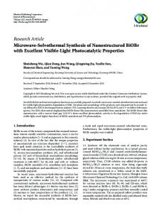
(1) Acmite Synthesis In a typical synthesis [Table I (Acm0)], 2.1 g silica powder (SiO2, 99.5%; U.S. Silica Co., Berkeley Springs, WV, CAS# 14808-60-7), 5.6 g sodium hydroxide (NaOH, 98%; Alfa Aesar, Danvers, MA, CAS# 1310-73-2), and 15 mL 1,4-butanediol (henceforth referred as 1,4-BD, 99%; Sigma Aldrich, St. Louis, MO, CAS# 110-63-4) were mixed in deionized (DI) water (55 mL) for 10 min by magnetic stirring. The solution was then transferred to a 125-mL Teflon-lined autoclave (model #011908; Parr Instrument Company, Molin, IL). Before coating, a 1″ 9 1″ 9 1/16″ ASTM 1008 low carbon steel coupon [(Fig. 1) McMaster-Carr, Elmhurst, IL] with surface roughness from manufacture was degreased with acetone (Fisher Scientific, Pittsburgh, PA, CAS# 67-64-1) and placed horizontally upon a Polyflouroalkoxy (PFA) support screen (Savillex, Eden Prairie, MN), and subsequently immersed in the solution. The autoclave was heated in an isothermal oven (Lindberg BlueM, model# MO1440C-1, mechanical convection) set to 240°C, operating in ambient atmosphere, and held for 72 h. Reaction temperature was chosen at the high end of the range specified by Riman and Cho, when NaOH was used as a mineralizer.22 After cooling, the sample was washed for 30 min in boiling water to remove any debris loosely attached to the surface. Reactantsolvent ratios, temperature, and time were examined as processing variables to determine their effects on the physical and chemical characteristics of the films (Table I).
D. Butt—contributing editor
Manuscript No. 32862. Received March 8, 2013; approved July 29, 2013. † Author to whom correspondence should be addressed. e-mail: terwhalen@gmail. com
1
2
Journal of the American Ceramic Society—Whalen et al. Table I.
Sample #
Acm0 Acm1 Acm2 Acm3 Acm4 Acm5 Acm6 Acm7
Summary of Reaction Conditions
H2O (mL)
1,4-BD (m)*
SiO2 (m)*
NaOH (m)*
Phase
Morphology
55.00 55.00 55.00 55.00 55.00 70.00 40.00 25.00
3.087 3.087 3.087 3.087 3.087 0.000 8.487 20.373
0.635 0.317 1.271 0.635 0.635 0.499 0.874 1.398
2.546 2.546 2.546 1.273 5.091 2.000 3.500 5.600
Acmite Magnetite/a-Fe Acmite Acmite Magnetite/a-Fe Magnetite/a-Fe Acmite Magnetite/a-Fe
Pinacoidal n/a Pinacoidal Pinacoidal n/a n/a Pinacoidal n/a
*mol per kilogram of H2O. All reactions performed at 240°C for 72 h.
coating to the underlying steel was evaluated via ASTM D 3359, test method B, which is the cross-cut tape test. First, the sample was cleaned by boiling in water for 30 min and dried at 75°C for 24 h. Subsequently, six horizontal and six vertical cuts were made through the coating into the steel with a razor blade. Cross-hatch test tape (M. E. Taylor Engineering, Inc., Rockville, MD) was applied to the sample and rubbed into place. After about 90 sec, the tape was rapidly pulled off at 180°. The resulting sample surface was then observed for percent removal of the coating.
Fig. 1. SEM image of 1008 steel prior to coating. Large scale bar: 100 micron, inset scale bar: 10 micron.
(2) Thermodynamic Simulation OLI Systems stream analyzer software (OLI Systems, Inc., Morris Plains, NJ version 3.2) was used to model the output of the system for the listed precursors. Thermodynamic parameters used by the software are determined by analysis and regression of primary experimental values. Examples of this procedure can be found in publications regarding thermodynamic modeling.24–28 Incipient precipitation point calculations were performed to determine the expected concentration of precipitated solids. A simulation of SiO2 concentration as a function of NaOH concentration was conducted using the following simplified inputs: 55 g H2O, 15 g 1,4-BD, 8 g Fe, 2.1 g SiO2, and 5.6 g NaOH, at 240°C, 5 MPa. Reduction and oxidation was allowed for the system, and solid precipitates Fe3O4 and NaFeSi2O6 were selected to highlight the phase field for acmite. (3) Characterization The phase composition of all samples was determined with X-ray diffraction (XRD) using a Siemens D500 powder diffractometer (Bruker AXS Inc., Madison, WI) CuKa radia� in the range 15°–70° (2h) with 0.02° step tion (k = 1.54 A) size and 1-s dwell time. Observed phases are given in Table I. A 10-nm-thick gold (Au) layer was sputter coated (Electron Microscopy Sciences, model# EMS 150T ES, sputter current 20 mA, maximim time 5 min) on the samples prior to SEM investigation. Microstructures were analyzed using a Zeiss Sigma field-emission scanning electron microscope (FE-SEM; Carl Zeiss, Oberkochen, Germany) at 5 kV. Average grain size was determined from the SEM images by measuring the diameter of at least 50 grains for a given sample. A Carl Zeiss Tiff Annotation Editor was used to measure the diameter of each grain along the diagonal. The adhesion of the
(4) Experimental Variability Slight variations in experimental procedure significantly affected results. Changes in precursor source, steel coupon orientation, and reactor liners all lead to either no acmite formation, or differing microstructures than expected. Grain structure varied when amorphous silica was used in place of crystalline quartz. The position of the steel coupons within the reactor was also crucial, with very high placement leading to smaller grains, and incomplete coverage. Very low placement of the coupon inhibited acmite formation. Due to the lack of stirring, concentration gradients of aqueous silica species was likely. Reusing the same reactor liner appeared to condition it, resulting in better coverage of the steel coupon after a few experiments. The “standard” condition reported was reproduced many times by adhering strictly to the above-described procedure. User variation led to the listed differences above. III.
Results
In a typical synthesis, the appearance of the steel changed from an initial smooth, metallic luster to a textured, glistening black color. An intermediate, matte black color was observed at shorter reaction durations. The textured surface qualitatively felt and appeared well adhered, with no part easily removed or damaged during handling and processing. The precursor solution appeared cloudy and white with visible SiO2 particulate solids settling after stirring. After the reaction, the solution had a brown coloration with both black and white particulate solids settled at the bottom of the container.
(1) Simulations Incipient precipitation point calculations predicted the amount of selected solid phases, Fe3O4 (magnetite) and NaFeSi2O6 (acmite), to be 0.867 m and 6.436 9 10�7 m, respectively. The thermodynamic simulation provided a theoretical range of precursor concentration yielding acmite, outside of which magnetite was the dominant solid (Fig. 2). The model provides an estimate of the minimum concentration of SiO2 and NaOH required to form acmite, 2.727 and 0.145 m, respectively. Lowering the system temperature did not appear to change the simulation output appreciably.
Solvothermal Synthesis of Acmite
3
Fig. 2. Thermodynamic simulation of acmite stability over a range of SiO2 and NaOH concentrations at 240°C and 5 MPa.
(a)
(b)
(c)
Fig. 3. Influence of SiO2 precursor concentration on coating morphology. Coupon surface after reaction using (a) 0.317 m (Acm1), (b) 0.635 m (Acm0), and (c) 1.271 m (Acm2) SiO2.
(2) Silica Concentration There existed a threshold silica concentration for the formation of acmite coatings at 240°C for 72 h, between 0.317 and 0.635 m, below which only magnetite was observed to form, as evidenced by XRD analysis, see Table I (Acm0, Acm1, Acm2). As could be seen from the microstructure given in Fig. 3(a), no grains were evident at a comparable scale (pitting was most likely caused by high solution pH). Above the threshold concentration (0.635 m SiO2), complete surface coverage with an entirely different morphology resulted, consisting of pinacoidal acmite grains with a mean grain size of 33 � 12 lm [Fig. 3(b)]. The observed crystals were determined by XRD to be phase pure acmite. Further increase in the SiO2 concentration (1.271 m SiO2) formed smaller grains of similar shape and phase [Fig. 3(c)]. (3) Sodium Hydroxide Concentration The effects of varying the NaOH concentration are summarized in Table I (Acm0, Acm3, Acm4) and Figs. 4(a) and (b). When the concentration of NaOH was 1.273 m, clusters of acmite grains having similar shape, but smaller size (3.225 � 1.625 lm) than the grains obtained from 2.546 m NaOH [Figs. 3(b) and 4(a)] were formed. In contrast, when the NaOH concentration was 5.091 m, acmite formation was inhibited [Fig. 4(b)] and magnetite and a-Fe were the only phases present [Table I (Acm4)]. (4) 1,4-Butanediol Concentration Experiments that varied the concentration of 1,4-BD showed that there existed a range of glycol concentration where (a)
(b)
Fig. 4. Influence of NaOH concentration on coating morphology. Coupon surface after reaction using (a) 1.273 m (Acm3) and (b) 5.091 m (Acm4) NaOH.
acmite formed, Table I (Acm0, Acm5, Acm6, Acm7) and Figs. 5(a)–(c). Without 1,4-BD, only magnetite formed, Fig. 5(a). Concentrations of 1,4-BD at 20.373 m and above also inhibited acmite formation. However, the microstructure of magnetite was clearly altered suggesting the elevated levels of 1,4-BD affected the final morphology, [Fig. 5(c)]. Within the range of 3.087–8.487 m of 1,4-BD, acmite grains of size 33 � 12 lm with a good surface coverage were observed, Figs. 3(b) and 5(b) for microstructure and Table I (Acm0 and Acm6) for phase composition (XRD).
(5) Effect of Time at 240°C Initially, only a-Fe (JCPDS 06-0696) was observed [Fig. 6(a) for the XRD and Fig. 1 for the morphology]. Upon 24 h of reaction, peaks indexed to magnetite (JCPDS 34-0185) began to appear, Fig. 6(b). The SEM image [Fig. 7(a)] and digital photograph [Fig. 8(a)] demonstrated that acmite grains had not yet formed by lack of surface texture and contrast. At 48 h and beyond, a-Fe and magnetite peaks were no longer observable, and only acmite (JCPDS 75-1610) peaks were seen [Figs. 6(c)–(d)]. Both an SEM image [Fig. 7(b)] and digital photograph [Fig. 8(b)] show incomplete coating coverage at 48 h. As reaction time was further increased to 72 h, [Figs. 7(c) and 8(c)] complete coating coverage was observed with no detectable change in microstructure between 72 and 96 h [Figs. 7(d) and 8(d)].
(6) Adhesion of Film to Steel An ASTM D3359 cross-cut tape test was performed on a coating formed via the standard reaction conditions. There was 0% removed area visible, that is, the surface at the edge of the cuts appeared unchanged after tape pull-off. Thus, tested samples scored a “5B,” or best possible rating per the guidelines of the standard. (7) Interface Cross Section SEM images of a focused ion beam (FIB) dug trench clearly showed a transition from bulk metal at the base, to a thin layer, and finally to large pinacoidal grains at the top (Fig. 9). Inspection of energy dispersive X-ray spectroscopy images
4
Journal of the American Ceramic Society—Whalen et al. (a)
(b)
(c)
Fig. 5. Influence of 1,4-BD concentration on coating morphology. Coupon surface after reaction using (a) 0 m (Acm5), (b) 8.487 m (Acm6), and (c) 20.373 m (Acm7) 1,4-BD.
oretical simulation and actual experimental results; (2) discrepancy between thermodynamic simulation and experimentation; and (3) what was inferred and speculated about the reaction mechanism.
(e)
(1) Overall Reaction The proposed overall reaction for acmite synthesis was the following:
(d) (c)
4SiO2 ðsÞ þ 2NaOHðaqÞ þ 2FeðsÞ þ 2H2 OðlÞ ! 2NaFeSi2 O6 ðsÞ þ 3H2 ðgÞ (b) (a)
Fig. 6. XRD pattern of coating after reacting for (a) 0 h, (b) 24 h, (c) 48 h, (d) 72 h, and (e) 96 h. *Unidentified peak.
supported the layered nature of the interface, noting that there was a distinct region of iron and oxygen separating the bulk iron from the mixture of iron, silicon, sodium, and oxygen. The schematic in Fig. 9 was a representation of the proposed layer configuration.
IV.
(1)
Observing the incipient precipitation point calculation, there were two suggested solid precipitates resulting from “standard” conditions, magnetite and acmite. Magnetite was assumed to be an intermediary species, and its appearance in the simulation inferred that the reaction did not go to completion. Starting with 3.5 9 10�2 mol of SiO2 should have resulted in 1.75 9 10�2 mol of acmite due to stoichiometry, but only 3.54 9 10�8 mol was reported by the simulation. A quick calculation from experimental results provided an estimated amount of precipitated acmite (Molacm). Assuming a uniform coating of 50 lm on all sides of the steel, the molecular mass of acmite (Macm) equal to 231.0 g/mol, and the density of acmite (qacm) equal to 3.52 g/cm3, then the volume of acmite (Vacm) can be found by subtracting the total volume (Vtot) from the steel volume (Vsteel): Vacm ¼ Vtot � Vsteel
Discussion
Inspection of experimental results lead to the following considerations: (1) proposed overall reaction compared with the(a)
(b)
(c)
(d)
Fig. 7. SEM images of coupon surface at progressive reaction times. (a) No observable acmite at 24 h, (b) partial coverage by acmite with distinct edges visible at 48 h, (c) full coverage of coupon by acmite at 72 h, and (d) little change in coverage at 96 h.
(a)
(b)
(c)
(d)
Fig. 8. Digital photographs of progressive reaction samples showing increasing surface coverage with time. (a) No observable acmite at 24 h, (b) partial coverage at 48 h, (c) complete coverage at 72 h, and (d) no additional change at 96 h.
Solvothermal Synthesis of Acmite
5
(a)
(b)
Fig. 9. (a) SEM image of a FIB dug trench, followed by EDX analysis of the layer interfaces. Note the region of overlap of Fe and O that excludes Na and Si. (b) Schematic pictorially describes the interface microstructure.
Molacm ¼
Vacm � qacm Macm
The result, 2.2 9 10�3 mol, was an overestimate of the amount of precipitated acmite, yet it is still an order of magnitude smaller than the theoretical yield. The extent of reaction is further considered in discussion on the reaction mechanism later.
(2) Thermodynamic Simulation Thermodynamic simulation of the “standard” conditions via OLI Analyzer software revealed a window for acmite formation at high concentrations of SiO2 and NaOH (Fig. 8). Comparison of the simulation with experimental results showed the following discrepancy. The minimum concentration of silica needed for acmite formation proposed by the simulation was much higher than the minimum concentration used experimentally, 2.727 m vs. 0.636 m SiO2. This difference may have been due to assumptions made when inputting the experimental conditions into the software. First, the simulation assumed a well-mixed system. The actual experimental solution was not continually mixed and initial settling of precursors was observed. The lack of mixing and settling suggested that a concentration gradient of silica species may have been present at the steel surface throughout the reaction, which was not reflected in the simulation. Second, well-mixed Fe was input as the weight of the steel coupons used. Clearly in practice, the amount of Fe in the system was much less than in the simulation and not uniformly dispersed. Third, the input pressure was estimated as the actual pressure, which was autogeneous and not precisely known. Also, the reactor vessels were not ideal, closed systems and it was anticipated that hydrogen may diffuse through the reaction liners and escape. Recalling reaction (1), release of hydrogen from the system would have allowed the reaction to progress further than the simulation predicted. This was observed by comparing the simulated solids precipitated, 6.436 9 10�7 m, versus the estimated experimental yield, 4.0 9 10�2 m. (3) Reaction Mechanism The evolution of the coating surface was evident from the time study (Figs. 7 and 8) and SEM analysis of the
steel–magnetite–acmite interface (Fig. 9). The initial surface of a-Fe was converted into magnetite and then after additional reaction time, only acmite was apparent at the surface. The transition from a-Fe to magnetite was expected. Conversion of steel surfaces to magnetite in highly alkaline oxidizing baths containing NaOH has been widely observed.11,12,29 However, how the surface progresses from magnetite to acmite was less clear. To form acmite, there must have been iron, sodium, silicon, and oxygen available and in the correct concentration at the surface of the coupon. Sodium ions should have been available from the dissolved NaOH. Silicon and oxygen were present in various silicate species. Iron was only available in the magnetite and the base steel substrate. Due to the low temperature and pressure, it was highly unlikely that iron ions could diffuse through the magnetite layer. Therefore, the most probable source of iron needed for acmite formation was either dissolution of the newly formed magnetite layer, or from the bulk steel via porosity of the magnetite layer. Dissolution was likely the rate-limiting step and a large amount of time would have been necessary for enough iron to be liberated from magnetite in order for acmite to nucleate and grow. The time study can be seen to support this proposed mechanism, as there was clearly a span of time (24–48 h) between which magnetite has formed over the entire surface and when acmite began to grow. After a long enough period of time, all the useable iron at the magnetite surface would have been consumed by acmite growth, and film growth will have stopped. 1,4-BD played a role in acmite formation, as results showed no acmite in pure water and no acmite with 1,4-BD concentrations exceeding 20.373 m. The exact mechanism was likely complex, but we can speculate based on previous findings in the literature. With regard to silica solubility, the use of glycols aid in the dissolution of otherwise poorly soluble oxides at low temperatures and pressures.30 Recalling the observed settling of precursors, 1,4-BD may have allowed higher concentrations of coordinated species to be present higher in the solution, near the steel surface. It has been shown that glycols can complex with silica.31 Alkali cations in solution, such as sodium, bridge the anionic silicate ions of these complexes, holding sodium and silica in a certain spatial orientation with each other.32 As iron ions were freed from the magnetite surface, the silica–sodium–1,4-BD complex may have coordinated with them, or simply having all three components in close proximity could be enough to have overcome the barriers to acmite formation.
6
Journal of the American Ceramic Society—Whalen et al. V.
Conclusion
A process to form a new type of conversion coating (acmite) on steel coupons was demonstrated. The ranges of reaction conditions allowing for acmite formation have been documented for SiO2, NaOH, and 1,4-BD at 240°C. In each case, the ability to control the grain size and morphology was noted. In addition, a minimum reaction time was established to create complete coverage of the steel substrate with acmite having a mean grain size of 33.1 � 12 lm at the following conditions: 0.635 m SiO2, 2.546 m NaOH, and 3.087 m 1,4BD in 55 mL DI water at 240°C for 72 h.
Acknowledgments The authors acknowledge Dr. Hebert of Materials Science and Engineering at University of Connecticut for his aid in analyzing the metal-ceramic interface with FIB and EDS techniques. Support for this work was received from DOW Chemical Corporation and PPG Corporation.
References 1
A. Decarreau, S. Petit, P. Vieillard, and N. Dabert, “Hydrothermal Synthesis of Aegirine at 200°C,” Eur. J. Mineral., 16 [1] 85–90 (2004). 2 D. K. Bailey, “Stability of Acmite in the Presence of Water,” Am. J. Sci., 267-A, 1–16 (1969). 3 S. Jodlauk, P. Becker, J. A. Mydosh, D. I. Khomskii, T. Lorenz, S. V. Streltsov, D. C. Hezel, and L. Bohat�y, “Pyroxenes: A new Class of Multiferroics,” J. Phys.: Condens. Matter., 19 [43] 432201 (2007). 4 G. F. Hays, “Now is the Time,” Adv. Mater. Res., 95, 1–2 (2010). 5 J. L. Mora-Mendoza, L. C. Saucedo-Robles, H. Rodr�ıguez-Clemente, ~ez, G. Zavala-Olivares, and M. J. Hern�andez-Gayosso, M. A. Gonz� alez-N� un “Integral Diagnostic in the Failure Causes of External Corrosion of a Natural gas Transport Pipeline,” Mater. Corros., 62 [8] 796–801 (2011). 6 B. K. Mahato, C. Y. Cha, and L. W. Shemilt, “Unsteady State Mass Transfer Coefficients Controlling Steel Pipe Corrosion under Isothermal Flow Conditions,” Corros. Sci., 20 [3] 421–41 (1980). 7 J. Rujisomnapa, P. Seechompoo, P. Suwannachoat, S. Suebca, and P. Wongpanya, “High Temperature Oxidation Behaviour of low Carbon Steel and Austenitic Stainless Steel,” J. Met. Mater. Miner., 20 [3] 31–6 (2010). 8 National Research Council, Research Opportunities in Corrosion Science and Engineerig. The National Academies Press, Washington, DC, 2011. 9 K. Asami and M. Kikuchi, “In-Depth Distribution of Rusts on a Plain Carbon Steel and Weathering Steels Exposed to Coastal-Industrial Atmosphere for 17 Years,” Corros. Sci., 45 [11] 2671–88 (2003). 10 M. Yamashita, H. Nagano, T. Misawa, and H. E. Townsend, “Structure of Protective Rust Layers Formed on Weathering Steels by Long-Term Exposure in the Industrial Atmospheres of Japan and North America,” ISIJ Int., 38 [3] 285–90 (1998). 11 H. Zhu, F. Cao, D. Zuo, L. Zhu, D. Jin, and K. Yao, “A new Hydrothermal Blackening Technology for Fe3O4 Coatings of Carbon Steel,” Appl. Surf. Sci., 254 [18] 5905–9 (2008). 12 J. Chen, K. Huang, and S. Liu, “Hydrothermal Preparation and Characterization of Octadecahedron Fe3O4 Film,” J. Alloy. Compd., 484 [1–2] 207–10 (2009).
13 H. H. Uhlig, Corrosion and Corrosion Control. An Introduction to Corrosion Science and Engineering. pp. 251–4, John Wiley and Sons, New York, 1971. 14 W. Eerenstein, N. D. Mathur, and J. F. Scott, “Multiferroic and Magnetoelectric Materials,” Nature, 442 [7104] 759–65 (2006). 15 G. E. De, A. A. Van, and S. G. Eeckhout, “Electronic and Magnetic Properties of a Natural Aegirine as Observed From its Mossbauer Spectra,” Phys. Chem. Miner., 25 [5] 378–88 (1998). 16 E. Baum, W. Treutmann, W. Lottermoser, and G. Amthauer, “Magnetic Properties of the Clinopyroxenes Aegirine and Hedenbergite: A Magnetic Susceptibility Study on Single Crystals,” Phys. Chem. Miner., 24 [4] 294–300 (1997). 17 N. L. Bowen and J. F. Schairer, “The Fusion Relations of Acmite,” Am. J. Sci., 18 [5] 365–74 (1929). 18 O. C. Kopp and L. A. Harris, “Synthesis of Grunerite and Other Phases in the System Silicon Dioxide-Sodium Hydroxide-Iron-Water,” Am. Mineral., 52 [11–12] 1681–8 (1967). 19 G. Q. Zhang and S. T. Zhang, “Synthesis of Sodium Iron Silicate (NaFe (III)[SiO3]2) Nanorods and Electrochemical Characterization,” Mater. Lett., 63 [2] 266–8 (2009). 20 K. Satome and Seiko Electronic Components, Ltd., “Apparatus for Hydrothermal Growth of Quartz Crystals”; Japanese Patent No. 01176297, 12 July, 1989. 21 R. A. Laudise and R. A. Sullivan, “Pilot-Plant Production-Synthetic Quartz,” Chem. Eng. Prog., 55 [5] 55–9 (1959). 22 R. E. Riman, S.-B. Cho, and Rutgers, The State University of NJ, “Inorganic Conversion Coatings for Ferrous Substrates”; US Patent No. 6159552, 12 December, 2000. 23 R. E. Riman, S.-B. Cho, and Rutgers, The State University of NJ, “Alkaline Conversion Bath for Inorganic Passivation Coating on Steel”; US Patent No. 6322898, 27 November, 2001. 24 R. D. Springer, Z. Wang, A. Anderko, P. Wang, and A. R. Felmy, “A Thermodynamic Model for Predicting Mineral Reactivity in Supercritical Carbon Dioxide: I. Phase Behavior of Carbon Dioxide–Water–Chloride Salt Systems across the H2O-Rich to the CO2-Rich Regions,” Chem. Geol., 322–323, 151–7 (2012). 25 P. Wang, J. J. Kosinski, M. M. Lencka, A. Anderko, and R. D. Springer, “Thermodynamic Modeling of Boric Acid and Selected Metal Borate Systems,” Pure Appl. Chem., 85, 22–7 (2013). 26 M. M. Lencka and R. E. Riman, “Thermodynamic Modeling of Hydrothermal Synthesis of Ceramic Powders,” Chem. Mater., 5 [1] 61–70 (1993). 27 R. E. Riman, M. M. Lencka, L. E. McCanlish, B. L. Gersten, A. Anderko, and S. B. Cho, “Intelligent Engineering of Hydrothermal Reactions,” Rev. High Pressure Sci. Technol., 7, 1358–61 (1998). 28 R. E. Riman, W. L. Suchanek, and M. M. Lencka, “Hydrothermal Crystallization of Ceramics,” Ann. Chim. - Sci. Mat., 27 [6] 15–36 (2002). 29 R. M. Hurd, and N. Hackerman, “Kinetic Studies on Formation of Black-Oxide Coatings on Mild Steel in Alkaline Nitrite Solutions,” J. Electrochem. Soc., 104 [8] 482–5 (1957). 30 R. M. Laine, K. Y. Blohowiak, T. R. Robinson, M. L. Hoppe, P. Nardi, J. Kampf, and J. Uhm, “Synthesis of Pentacoordinate Silicon Complexes from Silicon Dioxide,” Nature, 353 [6345] 642–4 (1991). 31 K. Y. Blohowiak, D. R. Treadwell, B. L. Mueller, M. L. Hoppe, S. Jouppi, P. Kansal, K. W. Chew, C. L. S. Scotto, and F. Babonneau, “SiO2 as a Starting Material for the Synthesis of Pentacoordinate Silicon Complexes. 1,” Chem. Mater., 6 [11] 2177–92 (1994). 32 W. Donh€arl, I. Elhofer, P. Wiede, and U. Schubert, “Elemental Silicon and Solid SiO Give the Same Products as SiO2 upon Reaction with AlkaliMetal Glycolates,” J. Chem. Soc., Dalton Trans., 9 [15] 2445–6 (1998). h