Some comments about the ToolKit InterViews 3.1 Jean-Daniel Fekete TicTacToon Consortium 45 rue Camille Desmoulins F-94230 CACHAN FRANCE 11th January 1993
1.
The TicTacToon project
1 . 1 . Project TicTacToon is a project aimed at developing and selling a computer system for professional cartoon animation. It has been created by the 2001 Company and started in 1992. It has recently been accepted and funded by the EEC as a four years project. The final system will be used by medium and large animation studios working on TV series. Partners of this project are of two kinds: animation studios and software developers. 1 . 2 . Partners Software developer partners include: •ּthe Digital Equipment Corporation Paris Research Laboratory, • the Laboratoire de Recherche en Informatique of University of Paris-South, • the 2001 Company. We have included a more complete description of the project and the partners in an appendix at the end of this document.
2.
General comments on InterViews
We have chosen InterViews as our development toolkit. In general, we consider it as a very good toolkit. It has several good points and a few drawbacks: •ּVery few and very clean basic objects. In contrast to other toolkits (Motif, MacApp, ET++), InterViews has a very small subset of basic objects (glyphs, style, observable/observer, canvas, event) and use them in a very regular and extensible way. •ּLarge InterViews programs can effectively be built and maintained. •ּLarge InterViews programs can effectively be built by composition of small cooperating objects. InterViews still has some deficiencies. In the following sections, we describe problems we had while using InterViews and propose some solutions.
3.
Drawing model (PostScript)
The graphic model proposed by InterViews is very close to the PostScript model. There are, however, some deficiencies which are usually easy to solve in a backward compatible manner. In the next subsections, we describe the problems we had and, in the last subsection, we summarize the changes we propose the solve them. 3 . 1 . Path with multiple subpaths (holes) PostScript has a notion of subpaths. Looking at [7] page 157, section 4.4, second paragraph: “A path is composed of straight and curved lines segments. These segments may connect to one another or they may be disconnected. The topology of a path is unrestricted: it may be concave or convex; it may contains multiple closed subpaths, representing several areas; and it may intersect itself in arbitrary ways.”
Path with holes are quite useful in graphic applications. A Latin character shape like the “A” has a hole. Not providing them means you cannot easily design a font editor with InterViews. Furthermore, there is a different interpretation of moveto between a Canvas and a Printer: the Canvas explicitly call newpath whereas the Printer does not. 3 . 2 . Filling rules PostScript and X11 define two filling rules: even-odd and non zero winding. Usually, the former is less intuitive than the latter. The even-odd rule is kept for compatibility with older systems like GKS. If a default rule must be chosen, the non-zero-winding rule is the betst candidate. Providing the two rules is a better choice. 3 . 3 . Join styles In PostScript and X11 (and most modern graphic libraries), the join between two consecutive stroked segments is treated according to a line join style parameter. Three styles are usually provided: mitered, round and beveled. The line join attribute not only modifies the graphics appearance of the joins; it also modifies the extent of the painted surface. More precisely, when the join style is miter, the corner between two consecutive segments with a sharp angle (less the 90 degrees) extends the bounding box of the two segments. This already happens in InterViews because the join style is mitered and cannot be modified. 3 . 4 . Line cap The line ending of most modern graphic libraries can also be parametrized. PostScript has three parametrizations: butt cap, round cap and projecting cap. X11 also has a fourth parameter called “not last”. The line cap parameter also modifies the extent of stroked lines. The value used currently by InterViews– not last – has the advantage of simplifying the computation of the extent of several connecting segments. 3 . 5 . Grid fitting InterViews uses floating point coordinates rather than integer coordinates which is a very good choice. However, when drawing on a canvas, each coordinate is transformed in printer points (1/72th of inch) by a transformation matrix kept by the canvas and, at a second stage, to pixel coordinates, by a simple transformation kept in the display. This is a bit different than on the PostScript model where the transformation kept by the graphic context does the two transformations in one step. The InterViews Reference Manual, in section 1.2.4, specifies that: "The default units for a coordinate are 'printers points', or 1/72 of an inch." And later, "Objects that need to generate consistent pixel sizes can explicitly round to wholepixel coordinate values using Canvas to_pixel_coord." The second step of transformation used by InterViews is prone to numerical rounding errors and complicate the precise handling of grid aligned shapes. Under PostScript, the matrix installed in the initial graphic state transforms coordinates to a unit of 1/72 of an inch but is not the identity matrix. A PostScript program can handle the matrix by itself if precise grid fitting is required. This is harder with InterViews since the application program has to manipulate non integral floating point values to control precise grid fitting. The PostScript model can be more precisely achieved by removing the (non-written ?) convention that the identity transformation is the initial transformation of a Canvas and providing a initmatrix member function in Canvas, so that a user could set the transformation matrix to the identity if he or she wants to control precisely the grid fitting. 3 . 6 . Summary of proposed changes 3 . 6 . 1 . Subpaths Adding subpaths requires a rewriting of the member functions Canvas::move_to, Canvas::close_path, Canvas::new_path, Canvas::stroke, Canvas::fill and Canvas::clip. They don't require any change in the Printer class.
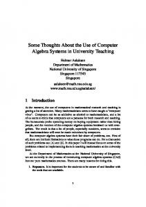
There is an easy way to implement subpaths under X11. We have made the changes to the Canvas data and member functions to operate correctly with subpaths with almost no overhead. It consists in constructing the XPoint table in a way suitable for filling, directly with XFillPolygon. Constructing this table means explicitly closing subpaths: adding a segment from the last point of a subpath to the first. It also requires the subpath to travel back to an origin point, usually the first point of the first subpath. When the resulting path should be filled, the last subpath is closed and a segment from the last point to the first point of the first subpath should be appended, as shown in figureּ1.
. Figure 1: constructing a path with subpaths. Subpath ends are marked with a bullet. The segment added is drawn with dashes.
For stroking, the first and last point of subpaths – not including implicitly closed subpaths – delimit segments that should be sent to X for stroking. This is a simple loop containing a XDrawLines. A subpath structure should be added in the Canvas representation to hold the information. 3 . 6 . 2 . Join style and Cap style The join style and cap style can be easily added by overloading the member function Canvas::stroke and add a new member function Canvas::eofill can be added. The same functions should be defined for Printer. 3 . 6 . 3 . Grid Fitting Changing the default transformation of a Canvas not be the identity can be done by adding a member function inittransform which returns the transformation required to map between printer points to device coordinates. The computation of X11 coordinates from InterViews coordinates could be further simplified by letting the transformation do the whole job of converting units and reversing the Y coordinates, as in PostScript. The advantage would be a much simpler code in path construction functions (just a transformation and storage in the XPoint structure). The drawback would be that inittransform would return different values when the canvas is resized. I don't think this would break any code since resizing a canvas disable all caching in glyphs, so any cached transformer based on the original value would not be referenced any more. 3 . 6 . 4 . Summary of Changes to the Canvas class interface Canvas { enum LineJoin { join_miter, join_round, join_bevel }; enum LineCap { cap_butt, cap_round, cap_projecting }; ... const Transformer& inittransform() const; void eofill(const Color*); void stroke( const Color*, const Brush*, LineJoin, LineCap ); };
4.
Drawing Aids and Tools
4 . 1 . No handling of geometric objects While quite complex geometric figures can be easily drawn, there is no general way of handling geometric objects in InterViews 3.1. By handling geometric objects, we mean tests for inclusion or intersection of geometric primitives. For example, testing whether a point is inside an allocation has to be done explicitly whereas simple box arithmetic would shorten the code and avoid typos. We propose to add some classes to support all the usual geometric operations involved in hit detection. See Appendixּ2 for details of the interface. 4 . 2 . Missing member functions to manipulate vectors in transformer class Surprisingly, there is no fast way to compute the transformation of a vectorial value with the transformer class. This computation is useful when transforming a line width for instance. Four member functions are required: interface Transformer : Resource { ... void transform_vector(Coord& dx, Coord& dy) const; void transform_vector( Coord dx, Coord dy, Coord& tdx, Coord& tdy ) const; void inverse_transform_vector(Coord& dx, Coord& dy) const; void inverse_transform_vector( Coord dx, Coord dy, Coord& tdx, Coord& tdy ) const; };
4 . 3 . No framework for direct manipulation Unlike InterViews 2.6 with Unidraw, InterViews 3.1 does not propose a framework for direct manipulation. We have already developed graphical editors with Unidraw and found it very effective for designing a prototype. However, specializing a prototype sometimes required deep changes in Unidraw classes. For instance, the feedback of direct manipulation is usually a rectangle. This is not adequate for precise positioning of graphical objects. Changing the shape of the selection is feasible for one object but requires major modifications for things like grouped objects. This is a main drawback for our application where we manipulate sophisticated shapes which have to be precisely placed. We have developed some backgrounds for a framework similar to Unidraw [1]. Obviously, some Unidraw mechanisms are very well thought and can be reused. We are currently working in integrating them in InterViews 3.1. The original article describing the multi-layer model is given in AppendixּIII. We have made some modifications to stick closer to the InterViews terminology and model. Our implementation is based on two classes: viewer and layer. A viewer is visible on one canvas. It displays a list of stacked layers. Each layer can be seen by several viewer. The viewer is responsible for the clipping and viewing transformation of its contained layers. Each layer contain some kind of graphics and manages the interaction of its graphic contents. As described in the AppendixּIII, we have identified five classes of layers, each responsible for a well understood task. There layers are: • background layer: this layer displays a background image.It can be used like the InterViews 3.1 Background class or like the Unidraw Page class. • Graphical constraints visualization layer: this layer usually displays a grid or other graphical formalism for representing geometrical constraints. It is very similar the the Unidraw Grid class.
• Application data layer: this layer displays the graphical objects that the user want to manipulate. Under InterViews 3.1, it usually contains the same kind of glyphs than those put in an InputHandler. Under Unidraw, it contains a GraphicViews. • Selected objects layer: this layer displays the selection, using shapes (e.g. handles) expressing the kinds of manipulations available. Event handling in this layer supports direct manipulation. • Lexical operations representation layer: this layer displays shapes expressing the status of input devices, like cursors, as well as transient shapes (e.g. “zoom animation”.) Several toolkit objects already use some ad-hoc version of this model. In InterViews, top level glyphs are usually instances of the Background class which contains a glyph and draws a background behind. Text interaction is built using a Character glyphs, correctly laid out by a Compositor, where selection is managed by a LRMarker and cursor has to be controlled by some other mean. All these object are drawn over a Background. Other examples like this one can be found in today’s implentation of InterViews 3.1 widgets: the Scrollbar, sliders, FieldEditor, Scrolling boxes, etc. These object, if implemented as layers rather than top-level glyphs, would allow an application to construct more sophisticated objects out of the existing ones. For instance, an XYSlider can be decomposed into a background and a main layer managing the Adjustable. The “thumb” of the XYSlider could easilly be modified in an application to contain some object name, like the virtual desktop manager of X11 tvtwm. The class interface is the following: interface Viewer : InputHandler, Observer { Viewer(Style*, GlyphIndex count); Viewer(Style*, Layer* = nil, Layer* = nil, Layer* = nil, Layer* = nil, Layer* = nil, Layer* = nil, Layer* = nil, Layer* = nil, Layer* = nil, Layer* = nil ); void allocate(Cnavs*, const Allocation&, Extension&); void pick(Canvas*, const Allocation&, int depth, Hit&); void draw(Canvas*, const Allocation&) const; void undraw(); void update(Observable*); void void void void void void
move(const Event&); press(const Event&); drag(const Event&); release(const Event&); keystroke(const Event&); double_click(const Event&);
GlyphIndex count() const; void remove(GlyphIndex); Glyph* component(GlyphIndex) const; void append_layer(Layer*); void remove_layer(GlyphIndex); void remove_all_layers(); GlyphIndex layer_count() const; Layer* layer(GlyphIndex) const; void insert_layer(GlyphIndex, Layer*); void replace_layer(GlyphIndex, Layer*); void layer_modified(GlyphIndex);
void layer_allocation(GlyphIndex, Allocation&) const; GlyphIndex focus_layer() const; void focus_layer(GlyphIndex); boolean tool_engaged(GlyphIndex) const; void tool_engaged(GlyphIndex, boolean); };
interface Layer : MonoGlyph, Observable { enum { background_layer, grid_layer, main_layer, selection_layer, select_layer, cursor_layer }; Layer(Glyph*); void pick(Canvas*, const Allocation&, int depth, Hit&); void attach_view(Viewer*); void detach_view(Viewer*); boolean is_involutive() const; boolean is_transient() const; void erase(Canvas*, const Allocation&, const Extension&) const; void redraw(Canvas*, const Allocation&, const Extension&) const; void change(GlyphIndex); boolean damage(Canvas*, const Allocation&, Extension&) const; boolean is_a(long) const; long id() const; void void void void void void
move(const Event&, Viewer*); press(const Event&, Viewer*); drag(const Event&, Viewer*); release(const Event&, Viewer*); keystroke(const Event&, Viewer*); double_click(const Event&, Viewer*);
void focus_in(Viewer*); void focus_out(Viewer*); void pointer(const Event&, Viewer*, Coord& x, Coord& y); GlyphIndex index(const Viewer*) const; void repick(int depth, Hit&, Viewer*); boolean in_selection(GlyphIndex, Viewer*); void in_selection(GlyphIndex, boolean, Viewer*); void clear_selection(Viewer*);
void tool_engaged(GlyphIndex, boolean); boolean tool_engaged(GlyphIndex) const; };
5.
Color model (multi-display issues)
There are two aspects in color management: 5 . 1 . Color space X11R5 has 6 different color spaces. They are classified in two categories: device dependent and independent. The first can always be expressed as an RGB triple whereas the second is usually translated into an XYZ triple. The XYZ triple can be transformed into a device dependent RGB through a device dependent function. The X11R5 distribution contains all the functions required to handle correctly the translations of color spaces. There should be a way to express the color space in which you define your color in InterViews. Bruce Cohen at Tektronix (
[email protected]) has proposed to define a class by color space. This is a convenient way to solve the problem from the user point of view. 5 . 2 . Color rendering Once a color is specified, it maps to a representation on the device. This representation is usually an approximation of the specified color because of device characteristics. Specifically, X11 defines six device classes, which behave differently to color requirements. 5 . 2 . 1 . Problems Under InterViews, the user does not control precisely how the colors are rendered, the choice is made by low level routines. This can lead to unfortunate graphics results and unbounded resource consumption under X11R5. Unfortunate graphics results happen when the user or the application programmer chooses a set of colors for the decoration of a graphic object, and let InterViews map them onto the device where the object is drawn. If the device characteristics does not distinguishes between two colors of the set, two objects will be indistinguishable graphically. Unbounded resource consumption happens when the user or the application programmer uses a lot of different colors for the decoration of a graphic object 1. If the device where the object is drawn uses a color map, the strategy used by InterViews consumes all the colormap entries first and then chooses arbitrary colors to render the remaining colors. One may argue that InterViews has a mechanism to check whether two colors are distinguishable. It means you can control some aspect of the rendering. When drawing a graphic object, the draw member function can test each color and try to find better colors if two are not distinguishable. While possible, this strategy is expensive and not flexible enough to give the application programmer all the information and means to make a good choice. The strategy used by InterViews, while acceptable on applications using few colors, is not sufficient for color demanding ones. 5 . 2 . 2 . The Color Management Strategy Object We have experienced a mechanism to solve this problem while keeping the device independence of the InterViews color model. It seems to work on most color demanding applications while being compatible with the actual use of colors. The role of the color management strategy object is to map between a color requirement and its device representation. 1 On most hardware, – i.e. with 8 bits per pixel, a usual 256 colors lookup table – a lot means more than
about 240 when working with in a standard X11 environment where about 16 colors are used by the window manager and some utility programs
Some recognized stategies are: allocate on demand, allocate a fixed set of colors, nearest solid color, dither (with variants), use default colormap, use a color map. The actual strategy of InterViews is “use default color map”, “allocate on demand” and, when it fails, “nearest solid color”. As seen, strategies can be combined to be more flexible. The specification of which strategy to use in a window would be searched in the window style. Strategies would need to be named and new strategies would also need to be searched by name. This is why two static member functions should be provided to bind new strategies to their names in the style parameter, and to create a strategy object given its style name. The implementation is designed to replace the current VisualInfo class, which does the low level color management in the 3.1 implementation. interface ColorManagementStrategy { ColorManagementStrategy(Window&); void init_color_tables(); const ColorRep* find_color(const Color&); static ColorManagementStrategy* find_strategy(Window&); static void register( const char* style_name, ColorManagementStrategy* (*fn)(Window&) ); };
6.
Event handling
6 . 1 . Input device extension 6 . 1 . 1 . Problem Only the two "core" devices are supported: keyboard and mouse. There is no provision for supporting additional input devices. X11 has now an input device extension mechanismּ[2] which can not be used under InterViews. Accessing other devices is very important for our project and an increasing number of applications is taking advantage of input devices like digitizers, button boxes or others. When input device events can be mapped into a core X event, InterViews can sometimes treat these events, if there is no need to distinguish them from a core device. This is the case for a regular digitizer for instance, where events are very similar to mouse events. Other devices, with more than two valuators, using the vocabulary of the X11 input extension, can not be handled by InterViews at all. Unfortunately, we use a Wacom digitizer which is pressure sensitive and therefore sends 3 values in each event. 6 . 1 . 2 . Proposed Solution Extending InterViews for managing the X input device extension would imply a small modification of the event class interface. It can be done like the following: interface Device { enum InputClass { key, button, valuator, proximity, focus, feedback
}; const char* name() const; Display* display() const; int input_class_count() const; Class input_class(int) const; boolean has_input_class(Class) const; boolean is_core() const; DeviceEventType last_type() const; unsigned long last_time() const; int axis_count() const; Coord axis(int) const; void x_axis(int); int x_axis() const; void y_axis(int); int y_axis() const; EventKeyCode keycode() const; boolean modifier_is_down(EventModifierKey) const; boolean button_is_down(EventButton) const; void focus(Window*); Window* focus() const; boolean open() const; boolean open(boolean) const; static int count(Display*) const; static Device* device(int) const; static Device* lookup(const Event&); };
The motion history buffer is also very important to get, an iterator is best suited to collect the values: interface DeviceHistoryIterator { DeviceHistoryIterator( Device*, unsigned long start, unsigned long stop ); boolean more() const; void next(); unsigned long cur_time() const; Coord cur_axis(int); const; };
6 . 2 . Control of devices InterViews event handling is much simpler than other X11 toolkits event handling. There is no way to control the event types received by the applications, all the mouse movements and key events are received, whether handled or not. We have never suffered from the lack of control of core devices yet. Receiving the mouse movements at a rate the application can handle seems reasonable; we have never noticed a slowdown due to this side of the communication with the X server.
Using our proposed Device mechanism, an InterView program interested by an extension device would simply open the device and receive automatically all events in the same way it receives core events. We think the motion hint mechanism – as currently used for the mouse – is adequate for most application. If all the events produced by a device would be sent to the application, it would produce a feeling of inertia since the events would not be processed at the rate they arrive. A drawing program will probably use the buffer history mechanism to get all the events sent during a direct manipulation. This mechanism not only speeds up the handing of events in client applications but also speeds up the server since the time of finding the window concerned by an event is not negligible. The DeviceHistoryIterator class is used to get all the events really generated by the device during a time interval. The core devices are propagated using and x and y coordinate. For devices with more than two axes, the mapping between the axis and the x and y coordinates should be configurable. A flying mouse could use the horizontal axis as x and the vertical axis as y. This mapping is done with the x_axis and y_axis member functions. The grab and the focus should also be handled in a specific way. We have not enough investigated in that direction to be sure about all the users needs. An experimental approach, providing the most obvious behavior at first and responding to users comments, would certainly answers the question.
7.
Contributions
We have already implemented most of the proposed changes in InterViews 3.1. They will be available soon on a ftp site. Here is a list of the contributions •ּAll modifications to stick closer to the PostScript model. The modifications are in the Canvas, CanvasRep and Printer classes. Most of them are straightforward. •ּColor Management Strategy code. This code involves some internal changes in InterViews. Our implementation does not fillow exactly the scheme described in this document. It does implement its functionnalities but is based on InterViews 3.0. •ּDevice Extension code. We have implemented the basic mechanism but never tested it on other extension than the Wacom digitizer. •ּBezierPath code. It is used every day on graphic applications. It is inspired from the Display PostScript extensions to PostScriptּ[8]. • Multi layer code. For now, we have implemented the basic mechanism and use it only for handling the drawing scene of our program. Used in this way, it can be considered as an extension of the Viewer object of Unidraw. We are planning to use in layout management to have functionnalities similar to Motif PannedWindow. • RPC and save/load of objects based on SUN RPC. Unidraw uses a Catalog object for storing and retrieving Components. We have chosen to use native XDR format for transporting and saving objects. This choice has been made because XDR/RPC are available on most workstation since they are required to use NFS and NIS (Sun Yellow Pages). SUN RPC is usually used in conjunction with a program called rpcgen. This program translates a C like syntax describing the data structures and/or the RPC protocol into C sources and headers to implement the translation in network order of data structures and the RPC transport of these structures. The RPC library is free so we have modified the rpcgen program to produce C++ programs and extend a bit its syntax so that it can be used effectively for storing objects in file as well as sending them to the network.
8.
Bibliography
[1] Jean-Daniel Fekete, A Multi-Layer Graphic Model for Building Interactive Graphical Applications, in Proceedings of the Graphics Interface'92 Conference, Vancouver, Canada. [2]ּMIT X Consortium, X11 Input Extension Library Specification.
[3]ּM. Beaudouin-Lafon, Y. Berteaud, S. Chatty, Creating Direct Manipulation Applications with Xtv, Proc. European X Window Conference (EX), Nov. 1990. [4]ּThierry Pudet, Dessin à main levée et courbes de Bézierּ: comparaison des algorithmes de subdivision, modélisation des épaisseurs variables. Thèse de Doctorat (PhD Thesis), Dec. 1992. [5]ּMichel Gangnet et al., Incremental Computation of Planar Maps, in Proceedings of SIGGRAPH'89 Conference. [6]ּJean-Daniel Fekete, WWL: A Widget Wrapper Library forּC++, Programmer's Manual, (available by anonymous ftp on export.lcs.mit.edu under pub/contrib/wwl-1.2.tar.Z). [7]ּAdobe Systems Inc., PostScript Language Reference Manual, Addison-Weseley, Reading, Mass., Second edition, 1991. [8] Adobe Systems Inc., Programming the Display PostScript System with NextStep, Addison Weseley, Reading Mass., 1991.
9.
Appendix I: Description on the TicTacToon Project
The 2001 Company has been created in 1989. Its goal is to design a computer system for professional animation. 2001 founders come from a pionnering animation company – Label 35 – which has produced high quality TV series with a custom PC based system. Label 35 system is vector based but half of the animation work is done on paper. Only the painting, placement and shooting on film is done on computers. While economically concurrential, PC based systems cannot provide an environment usable by artists to sketch and draw. The translation of paper work to computer is an expensive task of the process and causes a lot of problems: loss of information, loss of feedback, etc. 2001 has worked since 1989 to prove that all stages of traditionnal animation could be carried out with a workstation with no loss of quality and no long training for professional traditionnal animators. 9 . 1 . Zero Paper Most computer based animation programs (Disney Pixar system, Hanna&Barbera system, PC based QuickCell Animation system) are pixel based. They rely on hand drawing of animation on paper, scanning the drawings, painting by seed fill on computer before shooting the images and erasing the bitmaps. We have chosen and proven feasible the production of high quality animation directly on computer from the scenario to the shooting. We call it "zero paper animation". 9 . 2 . Why Vector Based Animation ? Vector based animation is useful because it is resolution independent, dimension independent and usually consumes less storage than pixel based animation. It is also easier to modify since each part of a drawing can be scaled, rotated, copied, its thickness can also be changed, as well as all its graphical attributes. Animations stored in a vector based format can be plaid at low resolution for line-tests or quick proofing. They can be shooted at TV resolution, either PAL (768 x 576) or NTSC (512x512). They can be shooted at HDTV resolution (2100x1200) and cinemascope at higher resolutions (up to 4096 points horizontally). Animations can be reused in different contexts (shrunk or grown, with different colors, flipped left-right, etc.) Animating a crowded street does not cost so much if the TV series can reuse the characters figuring in the crowd which is almost always the case. Pixel based animation use a lot of storage (1.2Mo for a raw RGB file, usually about par character per image with an alpha channel) and cannot be easily geometrically transformed without a loss of quality. 9 . 3 . What makes Vector Based Animation possible today ? Vector based animation has been made possible by the following new factors: •ּReal time and high quality curve fitting of points produced by a good digitizer. The Wacom cordless pressure sensitive digitizer is adapted to free hand sketching and drawing.
Thierry Pudet at DEC PRL [4] had designed a library which does the curve fitting in real time of the digitizer output. It produces a curve describing the outline of the stroke as if it were drawn using a thick brush, the thickness varying with the pressure. •ּReal time picking and painting of planar maps: PRL has designed a library called MapKernel [5] which can be used to paint vector based shapes as if they were pixel based. Like with seed fill, you click in a zone and it gets colored. The difference is that MapKernel returns a vector based description of the region to color so a colored drawing is still resolution independent. •ּAvailability of high-level toolkits to design, test and modify quickly interfaces where the ergonomic is essential. Professional animators are not ready to abandon their pencil easily. They need to be convinced that a computer tool will give them good results and a feeling not too far from their traditional tools. Real skilled animators are not easy to find so we can not rely on some particular animators ready to join the computer animation community. Tuning an interface requires hundreds of modifications, going from small adjustments to overall redesign of a set of functionalities. The higher level of abstraction we have, the better we can tune the interface. •ּAvailability of a new generation of processor with enough computing power. We have tested the prototypes on DECStations 5000. Their speed is not far from being acceptable for each of the programs run independently. If we want to be able to line-test a small animation while drawing, we need more power. Our target machine is a workstation with the DEC Alpha processor. 9 . 4 . Background of partners The DEC Paris Research Laboratory is actively working in the field of computer graphics and Computational Geometry (see bibliography at the end). The LRI of Paris-South contributes in the field of toolkit and user interface designּ[3,6]. 2001 founders have already designed a computer aided system which produced some French higher quality TV series.
10.
Appendix II: Details of the Geometric Objects
interface BezierPath { BezierPath(); BezierPath(const BezierPath*); BezierPath(const BezierPath&); void void void void
move_to(Coord, Coord); line_to(Coord, Coord); curve_to(Coord, Coord, Coord, Coord, Coord, Coord); close_path();
void transform(const Transformer&); void fill_extent( Coord& left, Coord& bottom, Coord& right, Coord& top void stroke_extent( Coord& left, Coord& bottom, Coord& right, Coord& top, Coord width, Canvas::LineJoin, Canvas::LineCap ) const; boolean in_fill(Coord x, Coord y) const; boolean in_fill( const BezierPath*, const Transformer* = nil ) const; boolean in_eofill(Coord x, Coord y) const;
) const;
boolean in_eofill( const BezierPath*, const Transformer* = nil ) const; boolean in_stroke( Coord x, Coord y, Coord width, Canvas::LineJoin, Canvas::LineCap ) const; boolean in_stroke( const BezierPath*, Coord width, Canvas::LineJoin, Canvas::LineCap ) const; int count() const; const BezierPathElement& element(int) const; };
A Bézier path is composed of segments. Each segment has the following type: interface BezierPathElement { enum { close = -1, move = 0, line = 1, curve = 3 }; BezierPathElement(int degree); BezierPathElement(const BezierPathElement&); BezierPathElement(const BezierPathElement*); BezierPathElement& operator = (const BezierPathElement&); int count() const; const Point& control(int) const; Point& control(int); const Point& last() const; void extent( Coord& left, Coord& bottom, Coord& right, Coord& top ) const; boolean intersects(const BezierPath*) const; void split_left(); void split_right(); };
For convenience, an iterator object is provided for iterating on paths and on path elements. interface BezierPathIterator { BezierPathIterator(const BezierPath*); BezierPathIterator(const BezierPath&); boolean more() const; void next(); const BezierPathElement& cur() const; void cur(Coord& x, Coord& y) const; };
Finally, a path segment can be split into line segments as close as required from the real segment. This decomposition is carried out by the BezierPathElementIterator object. It takes a path element and a tolerance value. It returns a list of points describing a polyline where each line segment is not farther from the real curve than the tolerance argument.
interface BezierPathElementIterator { BezierPathElementIterator( const BezierPathElement&, float tolerance = 1 ); boolean more() const; void next(); Point& cur() const; void cur(Coord& x, Coord& y) const; };
The Point arithmetic is obvious and is defined in a way similar to the header file of the book Graphic Gems. It is simply translated in C++.