and rotations. The integration procedure necessary to obtain the total stresses needs to satisfy the criterion of âincremental objectivityâ, introduced by Hughes.
Compurm
Pergamon
SOME
0045-7949(95)ooo19-4
& Srrucrures Vol. 56, No. 2/3, pp. 249-267. 1995 Copyright 0 1995 Elsevier Science Ltd Printed in Great Bntain. All tights reserved 0045.7949195 $9.50 + 0.00
COMPUTATIONAL ISSUES IN LARGE ELASTO-PLASTIC ANALYSIS
STRAIN
G. Gabriel and K. J. Bathe Massachusetts
Institute
of Technology,
Cambridge,
MA 02139, U.S.A.
Abstract-The stress integration procedure proposed by Eterovic and Bathe [Inr. J. numer. Merh. Engng 30, 1099-l 114 (1990).] is studied in detail. The elasto-plasticity formulation is based on the use of the total logarithmic strains and Cauchy stresses, and the Euler backward method of time integration. The accuracy of the procedure is assessed in the solution of various analysis problems and is compared with the accuracy of other schemes. Two important conclusions are reached. First, for a selected level of accuracy, the use of the total strain formulation, in general, allows larger time steps than the use of a stress-rate based formulation (such as a formulation based on the Jaumann stress rate). Second, the original procedure of
Eterovic and Bathe can be improved in accuracy by using the trapezoidal rule with a measure to limit the magnitude of the elasto-plastic strain increment per step. This improvement allows for the change of principal stress directions during the incremental step. This capability seems to be unique to this formulation and time integration.
Lee [8] enumerated the difference formulations (1) and (2) to be:
1. INTRODUCTION
Large displacement and large strain inelastic response calculations are pursued to an increasing extent. Most commonly finite element procedures are used. An important basic ingredient in such a solution is the evaluation of the stresses, i.e. when the total strains have been calculated, it is necessary to evaluate the corresponding stresses and material internal variables [2]. In the infinitesimal theory an additive decomposition of the strain rate tensor is used, see Refs [3] and [4]. c, = i$ + i;. (1)
l
Of course, for small elastic strains assumptions (1) and (2) are identical. The stresses are usually obtained by an integral based upon the constitutive equations. In this integration process we can identify two specific difficulties. Firstly, the material rigid rotations need to be integrated accurately, and, secondly, the integration should allow for the change in the principal axes of the stress tensor during each time step. There are two different approaches. The “ratetype” formulation makes use of the hypoelastic material law, which expresses the time rate of change of the stresses with the time derivative of the strains and rotations. The integration procedure necessary to obtain the total stresses needs to satisfy the criterion of “incremental objectivity”, introduced by Hughes and Winget [9] and further elaborated upon by Rashid [lo]. This author also introduced the notions of “weak objectivity” which means that the algorithm is objective for special input motions, such as pure rotations or pure stretches, and “strong objectivity”
the use of the logarithmic Hencky strain is necessary to ensure isochoric plastic flow; the shear modulus is a function of the plastic strain state for certain loading conditions.
Lee [8] introduced a new formulation, based on a conceptual stress relaxed intermediate configuration. If the complete motion of the body of interest is described by the deformation gradient X, then the motion from the initial to the ‘stress free’ configuration is given by the plastic part of the deformation gradient Xp and the motion from this configuration to the final state is given by XE. Therefore we have x = xsxp.
the
The elastic and plastic parts of the displacements, respectively, are additive. Since the strains are nonlinear expressions in the displacements, they are in general not additive. The elastic part of the deformation gradient premultiplies Xp and is only a function of the stress state, while the plastic part is also given by the history of plastic flow. The product (2) is not commutative in general, as are the strains in the additive decomposition.
Green and Naghdi [5] extended this approach to the finite deformation theory analysis. This formulation was studied by Bathe et al. [6], [7] and it was shown that: l
between
(2) 249
250
G. Gabriel and K. J. Bathe
which means that the algorithm is objective in the presence of both stretches and rotations. Several procedures have been proposed during recent years to integrate the stresses accurately in rate-type formulations, see also Pinsky et al. [I 11; Flanagan and Taylor [ 121; Weber et al. [ 131; NematNasser and Li [ 141, [15]; and Wang and Atluri [16]. It was demonstrated by Kojic and Bathe [17] that the rate-type approach introduces unphysical residual stresses even for the closed elastic strain paths of a simple plane stress combined tension-shear problem. A completely different approach is based on using a “total formulation”. In this case the criterion of “strong objectivity” is trivially satisfied, because the total stresses are obtained using the total strains, see for an early contribution using this approach Bathe et a/. [18]. This approach is more reasonable from a physical point of view than the rate-type approach. The question of choosing an incremental stress measure does not require special attention and the formulation of an incrementally objective stress update algorithm is no longer necessary. For large strain elasto-plastic analysis using “a total formulation” Eterovic and Bathe [I] proposed an efficient algorithm using logarithmic strains to obtain the stress state for a given deformation gradient. The basic idea of this algorithm is to use a hyperelastic approach to determine the elastic predictor stresses exactly,t and then a plastic relaxation process to obtain the final stress state. The applicability of this procedure depends on whether a kinematical decomposition of the deformation gradient into an elastic and plastic part is possible. Furthermore, the plastic evolution equation has to be integrated so that the stress state is obtained from the elastic deformation state at the end of every time step. There have been several contributions regarding “total formulations” and stress evaluations, see Simo and Ortiz [19]; Simo [20], [21], [22]; Moran et al. [23]; Weber and Anand [24]; and Peric [25], [26]. A finite element formulation for finite strain elasto-plastic calculations was given by Dvorkin et al. [27]. However, if the principal axes of the stress tensor are changing during the time step all the above procedures produce step-size dependent errors in the direction of the principal axes. The objective of this work was to study in detail the procedure of Eterovic and Bathe [1], and the procedures of other researchers, compare these techniques and identify possible improvements. Of particular interest is the error introduced due to a change in the principal stress directions.
2. BASIC EQUATIONS
2.1. Kinematics To describe the elasto-plastic deformation of a body we assume the deformation gradient to be multiplicatively decomposable into elastic and plastic parts X=XEXP
where the superscripts E and P denote the elastic and plastic parts of deformation, respectively. This assumption is widely used in crystal plasticity. Furthermore the spatial velocity gradient L can be written as L = Xx-’
= La + LP
(4)
with LE = XE(XE))’ L, = X%P(XP)-‘(XE))‘.
(5)
The velocity gradient can be divided into its symmetric and antisymmetric parts to obtain the velocity strain tensor D and the spin rate W L=symL+skwL=D+W
(6)
with symL=i(L+LT) skw L = f(L - LT).
(7)
Since det(XP) = 1 and therefore det(XE) > 0 the elastic part of the deformation gradient admits the polar decomposition Xa = REUE
(8)
where RE is the orthogonal elastic rotation tensor and UE is the positive definite, symmetric, elastic right stretch tensor. The elastic strains are defined as EE = In UE.
(9)
2.2. Stresses The elastic domain is described by the yield condition. For this purpose the shifted stress deviator S is introduced as S=T’-B T’=devT.
t In the absence of plastic flow the solution is given at this point without any incremental integration.
(3)
(10)
T is the Cauchy stress tensor and B is the back stress tensor describing the anisotropic resistance to plastic
Computational
issues in large strain elasto-plastic analysis
flow [28] or the kinematic hardening, respectively. The effective stress is obtained from the second invariant of S
251
The “modified” plastic velocity gradient and the “modified” plastic strain velocity tensor are given by & = (XE)-rEPXE=
S=&G3
Xr(XP)-’
(11) tip = sym L’.
and the condition
yield
surface
can
be
described
by
(21)
the The elastic-plastic deformation state is completely described by the following state variables
@(s,a)=s
--a
=o
(12) {X, Xp, T, 6, B).
where c is called the deformation resistance or yield stress and @J< 0 describes the elastic domain. The normal onto the yield surface is given as
These quantities can be replaced equivalently by an associated set of “modified” variables defined by the equations above
(13)
For isotropic materials an elastic work conjugate “rotated” stress tensor T can be introduced (see e.g. Atluri [29], Hoger [30])
T.J?~=JT.D~
(14)
with the elastic velocity strain tensor DE = sym LE, the Jacobian of the deformation mapping J = det X and the Cauchy stress tensor T. We use that the rotated stress tensor and the Hencky strain measure commute ~~,EEI=T’EE-EET=o and the “rotated”
{X, xp, ?, cr,B}. The stress-strain
2.3. “Rotated quantities”
stress tensor
(15) can be written
T = JRETTRE.
as (16)
Similarly the “rotated” back stress tensor and the “rotated” stress deviator are introduced
(22)
(23)
law is now taken to be T = Y[EE]
with the fourth-order
isotropic
(24) elastic material
2=2p1+(K--fp)1@1
tensor (25)
where I and 1 are the fourth- and second-order identity tensors, respectively. The shear modulus p and the bulk modulus K are the elastic constants. 2.4. Plastic domain-evolution equations The evolution equation for the plastic part of the deformation gradient is given by XP = LPXP.
(26)
Assuming that the skew-symmetric part of cp vanishes, or in other words, the elastic spin equals the continuum spin, which is the usual assumption in the theory of isotropic polycrystal metals prior to the development of texture [24, 31 and 321 it follows
E = J(RE)TBRE Xr = jjPXP. 3 = J(RE)TSRE. Of course,
In the case of the associated flow rule (the classical theory) the direction of plastic flow is taken to be the same as the direction of the outward unit normal onto the yield surface
we also have S=F-B ?’ = devT.
The effective
(18)
stress is then equal to s =
J-‘m
and the unit normal R = (RE)‘NRE becomes
(19) onto
(27)
(17)
the
yield
surface
(20)
tip = sym Lp = $epfi.
(28)
These equations follow directly from the reduced dissipation inequality, for details see e.g. Eterovic and Bathe [33]. It remains to define the evolution equations for the hardening parameters. To describe hardening, use is made of the hardening rules
6 = $(l - /?)HiP
(29)
G. Gabriel and K. J. Bathe
252
with the hardening modulus H and the hardening ratio fi considered as functions of the equivalent plastic strain ep
The general solution
of this differential
equation
f+A~Xp=(exp(~,‘iAiDP(r)dr)):XP.
is (34)
H = H(eP) B = B(eP).
(30)
We have isotropic hardening when /I = 1 and kinematic hardening when /l = 0. The more general description in eqn (29) corresponds to mixed hardening.
Taking the inverse and premultiplying we obtain
with ‘+A;,
‘+A~XE=X:exp(-~~iA’~P(r)dr)
(35)
where X: is the trial elastic deformation gradient x; = r+A;x (hx’)-‘.
3. COMPUTATIONAL
The complete
computational
procedure
consists of:
(1) The stable, accurate and efficient integration of the plastic evolution eqn (27) to obtain the final stress state at the end of the time step. (2) The calculation of a consistent tangent matrix used in the Newton (or some other) iteration process. We note that the first item is essential for solving the given problem accurately, while the second item improves the convergence of the iteration process and may also decide whether an actual engineering problem can or cannot be solved. In this paper we consider the integration of the stresses. It is assumed that the variables are given for the converged configuration at time t
{AX, 6X’, ‘T, ‘CT, ‘8).
(31)
The objective of the time integration algorithm is to calculate corresponding to the given deformation gradient ““AX the remaining variables for the updated configuration at time t + At {‘+A;X,‘+A;
XP
) r+AfT
, l+Ar,
,‘+A%).
Also, the final elastic written as l+A;,E
r+A;xE
the evolution equation gradient, equation (27)
P(t) = bP(t)XP(t).
of the
plastic
(33)
t Note that in this case UE and DP have the same eigendirections during the time step t < z < f + AZ,both are symmetric and their product is still symmetric.
state
I+A;x(~+A;xP)-I,
can be
(37)
=
f+A;,E
l+A;,E
X”, = RE,US.
(38)
It follows from eqn (35) using eqns (36) to (38) that REUE *
From
=
I+AI OR
*
E’+A,$JEexp(~‘A’L)P(r)dr).
(39)
eqns (18), (20) and (28) we have [Ibp>Sl = PP> (T’ - B)l =[DP,P]+[8,bP]=o.
For a motion with constant directions it follows from (29b)
(40) principal
[R, D’] = 0.
stress
(41)
For isotropic materials the material stress deviator commutes with the elastic part of the strains (15) and it follows fl’, EE] = 0. Because
3.1. Kinematics
=
deformation
Since det (X”,) > 0 and det (‘+AAXE) > 0 we have the polar decompositions
(32)
The proposed integration procedure corresponds to the algorithm of Eterovic and Bathe [l], but a simple refinement allows for the rotation of the principal axes of the stress tensor during the time increment. The result is that larger time steps can be used in some analyses.
Consider deformation
(36)
PROCEDURE
(42)
of [EE, UE] = 0 we finally have [IY, UE] = 0.
(43)
This equation holds for all times during the deformation process. Thus, it follows that the trial elastic rotation tensor is equal to the final elastic rotation tensor for every motion with constant principal axes of the stress tensort RE, = f+A;Rr
(44)
Computational
253
issues in large strain elasto-plastic analysis
and therefore
We assume that the time derivative of the equivalent plastic strain is constant and equal to
LJ: = r+A;UE exp( [+A’Dp(r)
(45)
dr).
r+AreP &P(7)
If the principal changing, it follows strain law that
axes of the stress tensor are from eqn (39) using the Hencky
‘+AiRE = Ri exp(E:)
Further
_
reP
= const.
(52)
N(z) dz z At r+zAtR
(53)
=
At
we assume
that
f+Af
exp( -l,“A’Dp(r)
sI
dr)
x exp( - '+A;EE).(46) We can show that for total elastic strains occurring in most practical calculations (up to 10%) the product of the exponential terms on the right-handside is approximately equal to the identity. Hence, with an acceptable error, eqns (44) and (45) can still be used, see Appendix.
where u. is the Euler method Then eqn (51) becomes
s
integration
AI
I +
I +
parameter.
aA
D’(z) dz = i(‘+A’eP - ‘e’)w
f
(54)
and r+.A’S=(l
--)‘S+tl’+“‘S.
(55)
Using the hardening rule eqn (29a), eqn (52) and the consistency condition S = 6 we have
3.2. Stresses Using the Hencky
strain measure
we obtain
from r+AIS
eqn (45) !+A, EE = *
r+A$E
+
D’(7)
sf
dz.
=
t+Arc
(56)
dz = q[(l - cc)‘s + c( ‘+AfS]
(57)
These equations
(l+AleP
_
reP)r+At,
yield
l+Af bP(7)
with
r+Af =r;
r+Atff.
f,, +
(47)
Following Eterovic and Bathe [l] and using the elastic stress-strain law (24) we obtain the evolution equation for the “rotated” stress deviator r+Afp
=
-3
v(7)
ds
sI
r+AreP
3 (48)
4 =
2
,J’~
+a
_
GI ‘J’~
+
_
reP
dl I + A’J
r+Ar~(r+At~P
_
.
rs
reP)r+Atg
(58)
f+Afff
and using the mean stress Using the hardening tr’+A’T=trT*=3rctrES.
rule eqn (29b), we have
(49) [+A:
(1 - fl) HDP(z) dz.
(59)
Assuming that the hardening parameters constant during the time step and equal to
are
‘+A’&‘B+$
The “rotated”
stress tensor
is equal to
t+Ar~=r+A~~l+f(t~‘+A’~)l,
sf (50)
We note again that eqn (48) is an approximation if the principal axes of the stress tensor are changing during the deformation. However, this equation can still be used for a moderate amount of elastic strains and sufficiently small time steps. The proof and some remarks about suggested time steps are given in the Appendix.
H=‘+“‘H
(60)
we have t+At “A’B
=
‘B
+
f(l
_
r+Ay>
r+AfH
BP(t)
sI
3.3. Integration procedure Further attention is now focussed on solving integral in eqn (48). From eqn (28) we obtain
the
Combining
(61)
eqns (18), (48) and (61) yields r+Arp
(-r;-IS)=(
dz.
_
r+Arjj)
f+Ar
‘+A’Pp(~)~(~)dr. s,
(51)
+[2P
+$
- ‘+“‘B) r+A’H] [‘+“‘DP(T) dz. Jr
(62)
G. Gabriel and K. J. Bathe
254
The left hand side corresponds to a trial elastic stress deviator s, and using eqn (57) we obtain for general hardening S*=‘+A’S+c[(l
-cc)‘S+cX’+A’S]
(63)
where
C=
[3~ +(1 -‘+A’~)‘+A’H](‘+A’eP-‘eP)
to show such solutions. Furthermore, we note that using our procedure the value of the integration parameter a does not enter the elastic solution process. In this section we demonstrate the performance of the proposed algorithm in large deformation elasticplastic analysis. We use a norm r~ as a measure to evaluate the accuracy of our solution. This norm is taken to be (see Appendix)
(64)
‘J’S-cx”J’S+tL’+A~J~S +
tlf+Af~(z+AleP
_
reP)r+Arg
r+Af~
9 = ii i’+A”p”)dT II‘+$EE]]
:i
(67)
Therefore I+AIS
_ -
$-& [S, -
(1 - c()c ‘S].
(65)
The solution of eqn (65) has to be obtained by satisfying the yield condition (12) and this results in the effective-stress-function equation [2]
_‘+Q(
‘+AleP) = 0.
(66)
This equation can be solved numerically using a simple bisection algorithm, a Newton method or a secant method. The above computational solution is the one given by Eterovic and Bathe when CI= 1 is used. Using c[ = 1 we assume that the principal stress directions of the second term in equation (48) are the same as the principal directions of the other terms in that equation. Thus the directions of the final state are determined by the trial state. The solution is exact using the radial return method if the principal stress directions do not change during the step. In this solution process rigid body rotations do not affect the accuracy. If the principal stress directions (with rigid body rotations removed) change during the step an error is introduced during the time integration. This error depends on the step size. To reduce this integration error the parameter z = f can be employed. Namely using TV= f we allow for the change in the principal axes of the stress tensor during the time increment and can expect a better performance of the algorithm when such changes are significant. Of course, in elastic analysis, no such error occurs, irrespective of how large the change in principal stress directions is during the time step. We demonstrate these theoretical observations in the example solutions presented next. 4. NUMERICAL
EXAMPLES
We note that our algorithm yields accurate results according to the analytical solutions given in the Refs [lo-12,261 for pure elastic deformations and any amount of rigid rotation. Thus, there is no need
and determines a ratio between the plastic strain increment and the total elastic strains. In our calculations we used the spectral norm, see Ref. [2]. We also give a value marked nmax.allowab,e,which was obtained according to eqn (94). Of course, the value of the integration parameter c( will now affect the accuracy of the numerical results. If not mentioned otherwise the material parameters used in the example solutions are Shear modulus p Bulk modulus K Yield stress a0 Hardening modulus H
76.92 166.67 0.75 2.00
MPa MPa MPa MPa.
(68)
4.1. Simple transverse displacements without hardening We consider an in-plane isochoric deformation with no hardening according to the deformation gradient 1
x=0
jt
0
10
(69) 1I with y a constant, y = ?jt and 0 < t < 1. The analytical solution for this problem using the Jaumann rate based formulation is given for instance by Weber et al. [13] (see also Moss [34]). For convenience the deformation resistance against shear is denoted as k = oO/&. For sufficiently small values of it the material behavior is elastic and the stress components are i0
0
T,, = p sin(vt) Z-,, = ~(1 - cos(l;t)) = -T,,. Yielding
occurs at time t, to=+
Then for given by
(70)
arccos[l
t > t, the
(71)
-f(k)i]. elastic-plastic
solution
is
T,,=kcosY T,, = k sin Y = - T22
(72)
Computational
issues in large strain elasto-plastic analysis
0.45
0.4
0.35
0.3 cy E 2
0.25 -
S! 2 g
I
0.2
Jz In
-+-~
1
I
0.15
steps:
10
alpha-l
.O. steps:
A
alpha=
I .O. steps:
5
0
alpha=0.5.
steps:
5
-
I
0.1
olpho=0.5.
analytical
10
(Jaumann-based)
I 0.05
0 0
0.005
0.01
0.015
0.02
0.025
0.03
0.035
0.04
0.045
0.05
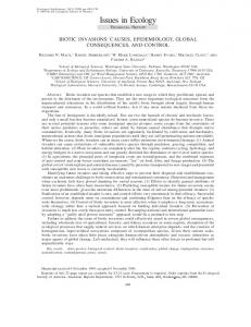
gamma Fig.
1. Simple
transverse
displacements
without
hardening,
small
deformations,
stresses T12
shear
(all stresses are nearly the same).
with
I=[~+(Y,-~)exp(-,j(I-lO))]
Y0 = arcsin
Ak
(73)
( 2P >
We obtained results using tl = 1 and c( = f as integration parameters, and compared our numerical solution with the analytical solution of eqn (72), but of course such comparison is only valid for small deformations. The shear and normal stresses and the norm q for Ij = 0.05 are shown in Figs 1-3. This region
0.005
0.0045
0.004
o.c.035
;
0.003 D
f ~1 0.0025 5 E z”
0.002
alpha=0.5.
- a-
steps:
olpha=l.O,steps:
10 10
o.M)15 ---0.001
-
alpha=0.5. steps: 5 (no first elastic step) alpho=l.O.
steps:
5
0 0
0.005
0.01
0.015
0.02
0.025
0.03
0.035
OS!4
0.045
0.05
gamma
Fig. 2. Simple transverse displacements without hardening, small deformations,
normal stresses Tl 1.
256
G. Gabriel
and K. J. Bathe
12 -
10
I'
a
g i!d z
4
2
0 0
o.M)5
0.01
0.015
0.02
0.025
0.03
0.035
0.04
0.045
0.05
gamma Fig. 3. Simple transverse
without hardening, norm q for a = l/2 and I (ratio between plastic strain increment and total elastic strain).
displacements
corresponds to small deformations, where the elastic and plastic parts of deformation are nearly of the same order. Larger deformations are dominated by plasticity. Figures 4-6 show the results for y = 0.5. We note that at large deformations the normal stresses are one to two orders of magnitude smaller
than the shear stresses. The shear stresss are always accurately predicted, even with large solution steps, and using a = 1 and a = f . However, the secondorder normal stresses are much better approximated when using a = f and AC within the recommended time step region (q < 2). For larger time steps the solution using t( = f starts to oscillate around the
0.45
1
F
l
II
0.4
0.35 I I
0.3
I
I I
cy ;I '1 0.25
I
I
1
i-z v) i
-2
0.2
1
i!i 0.15
alpha=0.5, Steps: 11
o-
alpha=0.5,steps:6
*
alpha=l.O,steps: 11
a-
alpha=l.O,stepS:6
-analytical
0.1 -
(Joumann-based)
0.05
04
0
I
I
I
I
I
I
I
i
I
0.05
0.1
0.15
0.2
0.25
0.3
0.35
0.4
0.45
I
I 0.5
gamma Fig.
4. Simple
transverse
displacement without hardening, large deformations, (all stresses are nearly the same).
shear
stresses
T12
Computational
issues in large strain elasto-plastic analysis
257
0.02
---0
-
alpho=OS.
a----*-
steps:
11
alpho=l.O.steps:ll - alpha=0.5.steps:
- a-
alpha=l.O,
6
steps: 6
0 0
0.05
0.1
0.15
0.2
0.25
0.3
0.35
0.4
gamma
0.45
0.5
lappc. 2596 strain1
Fig. 5. Simple transverse displacement without hardening, large deformations, normal stress Tl1.
analytical value and the solution away from this solution. Of course, is always satisfied. The reason for this behavior rotation of the principal axes of during the deformation.
Q
I
10
using CI= 1 drifts the yield condition is given by the the stress tensor
4.2. Simple transverse displacements isotropic and kinematic hardening
I 1
0
1
/
1 _
-+-
eta (steps:
-D-
eta (steps: 6)
11)
-
eta-max
/ 0
0.05
0.1
0.15
0.2
both
We use again the material parameters given in eqn (68) and use the deformation according to eqn (69) with 7 = 1, y = 3t and O< t < 1. This
E p
with
0.25
0.3
0.35
0.4
0.45
0.5
gamma
Fig. 6. Simple transverse displacements without hardening, large deformations, norm n for a = l/2 and 1 (ratio between plastic strain increment and total elastic strain).
258
G. Gabriel
and K. J. Bathe
I __
I T12(olpha=0.5.steps: 101)
.
T12 (alpho=0.5.steps: 11) F Tl2 (alpha=l.O.steps: 101)
0
Tl2 (olpha=l.O.steps: 11)
I
c
0+ 0
0.1
0.2
0.3
0.4
0.5
06
0.7
0.8
0.9
1
gamma Fig. 7. Simple transverse
displacements
with isotropic hardening, the same).
corresponds to a maximum principal strain of 48%. The results for isotropic and kinematic hardening, using small and large time-steps are given in Figs 7-9 and in Figs 10-12. An analytical solution is not given, but it is obvious that the solutions using t( = f and t( = 1 converge to the solution using c( = f obtained with small time steps. The norm q is again a good measure of the size of the incremental steps in the
0.07
shear stresses T12 (all stresses are nearly
solution
process. The maximum allowable value of q according to eqn (marked qmax.allowable ) was obtained (94). To illustrate the performance of our solution algorithm for very large deformations we include the results for a simple transverse displacement process of a pure iron specimen. Referring to Refs [35] and [36] we conclude that the maximum possible
B
I
0.06
, 0 _,A '-
,.-
Q " 0.05 -
1 the critical value is given by the term containing q3. We are able to determine the maximum allowable q comparing this term with the order
Computational
issues in large strain
of the total elastic strain. If we want this term to be at least two orders smaller than the elastic strains we should use
elasto-plastic
with the rotational
analysis
261
correction
R, =exp(E:)exp(-~+A’Dr(r)dr)exp(-i+A~EL)
It is obvious that the maximum allowable n depends on the order of the elastic strains. The larger the elastic strains, the smaller the value of r~ should be. The other restriction is given by the approximation used to obtain tD (see eqns (51)-(54)). We have not been able as yet to estimate the error introduced in this approximation. However, our numerical examples show that we can expect good results with a maximum relative error of less than approximately 0.1% using q E 1 and G(= f. The error will increase to approximately 1% using a = 1. We note that in some situations we can obtain accurate results using much larger values of n. However, for practical calculations we suggest to work in the region
For convenience
we write this equation
(A18)
as
R, = exp(E,)exp(-eD)exp(-E). Using
eqn (84) it follows
(A19)
that
R,=I+(E,-E-tD)+f(E,-E-CD)* +f([sD,
El + [E, &I + [ED,Eel)
+ O(llE, II)‘. Because
of the relation
(-420)
(93) it is easy to see that
(‘416) R,=I+f((cDE-EeD)+(EE,-E,E) where we can usually expect sufficiently accurate results. This equation means that the plastic strain increment should be of the same order as the total elastic strain. We now show that the trial elastic rotation tensor is approximately equal to the final elastic rotation tensor for any value of cz. Using eqn (46) we define ‘+$Rr=R:R,
CAS 56,2-3-F
(A17)
+ @DE, -Et
CD)).
(A21)
It follows from this equation that as long as all terms commute, the rotational correction R, is equal to the identity. If this is not the case, deviations from the identity matrix occur that are small compared to I as long as we work in the suggested time step region. Inaccuracy may only occur using very large time steps.