IEEE MICROWAVE AND WIRELESS COMPONENTS LETTERS, VOL. 18, NO. 1, JANUARY 2008
1
Space Mapping With Multiple Coarse Models for Optimization of Microwave Components Slawomir Koziel, Senior Member, IEEE, and John W. Bandler, Life Fellow, IEEE
Abstract—The performance of space mapping (SM) optimization algorithms depends primarily on the quality of the underlying coarse model. Models available in the microwave area can be cheap but inaccurate or accurate but too expensive. Here, we consider a multicoarse-model technique that allows us to combine the merits of both types of coarse models to substantially reduce the overall computational cost of optimization in comparison to traditional SM. Index Terms—Coarse model, engineering optimization, microwave design, space mapping (SM) optimization.
I. INTRODUCTION T is well known [1], [2] that the performance of a space mapping (SM) optimization algorithm depends on the quality of the underlying coarse model, which should be as good a representation of the fine model to be optimized as possible but also significantly less expensive than the fine model. Under these conditions, an SM algorithm can reach a satisfactory solution after a few fine model evaluations. Available coarse models are either cheap but inaccurate, e.g., an equivalent circuit, or accurate but too expensive, e.g., a microwave structure evaluated using the same simulator as the fine model but with a coarser mesh. In the first case, the SM optimization process exhibits computational overhead due to the excessive fine model evaluations necessary to find a good solution or the SM algorithm fails to find a satisfactory solution. In the latter case, the cost of solving the parameter extraction and surrogate optimization sub-problems, normally negligible, may determine the cost of SM optimization. A multimodel aggressive SM [3] deals with these problems through fine models of increasing accuracy. The outcome of the optimization stage using the less accurate model is the starting point for the next stage using the more accurate model. This increases the chance for SM to find a good solution although the optimization time savings are limited. The concept of a dynamic coarse model combining the equivalent-circuit and coarse electromagnetic (EM) model and ap-
I
Manuscript received July 11, 2007; revised September 18, 2007. This work was supported in part by the Natural Sciences and Engineering Research Council of Canada under Grants RGPIN7239–06 and STPGP336760–06, by Bandler Corporation, Sonnet Software, Inc., and by Agilent Technologies. S. Koziel is with the Simulation Optimization Systems Research Laboratory, Department of Electrical and Computer Engineering, McMaster University, Hamilton, ON L8S 4K1 Canada (e-mail:
[email protected]). J. W. Bandler is with the Simulation Optimization Systems Research Laboratory, Department of Electrical and Computer Engineering, McMaster University, Hamilton, ON L8S 4K1 Canada and also with Bandler Corporation, Dundas, ON L9H 5E7 Canada (e-mail:
[email protected]). Color versions of one or more of the figures in this paper are available online at http://ieeexplore.ieee.org. Digital Object Identifier 10.1109/LMWC.2007.911969
plied to SM optimization of LTCC radio frequency (RF) circuits was presented in [4]. An interpolation technique described in [5] allows us to create coarse models that are both accurate and sufficiently cheap. The coarse model (accurate but too expensive to be directly employed in the SM algorithm) is evaluated on a relatively coarse simulation grid and the modified model is obtained by interpolating this data. Hence, the coarse model is evaluated at a limited number of points which allows us to reduce the SM optimization time. This technique is efficient if the number of design 5) [5]. variables is small (i.e., Here we propose a multiple-coarse-model SM technique in which the accuracy of the basic coarse model is enhanced through standard SM modeling using the auxiliary coarse model (more accurate but too expensive to be directly used in SM optimization; typically, it is the model utilizing the same EM simulator as the fine model but with a coarser mesh). Our technique retains all the advantages of the method [5] but is not limited to a small number of design variables. II. MULTICOARSE-MODEL SPACE MAPPING OPTIMIZATION denote the response vector of a fine model of the deLet vice of interest. Our goal is to solve (1) where is a given objective function. We consider an optimization algorithm that generates a sequence of points 0,1,2, , and a family of surrogate models , so that (2) denote the response vector of the coarse model: less acLet curate than the fine model but much faster to evaluate. Standard are constructed from the SM [1], [2] assumes that models coarse model so that the misalignment between and the fine be a generic SM surrogate model, model is minimized. Let i.e., the coarse model composed with suitable SM transformais defined as tions. The surrogate model (3) where (4) are weighting factors. is a vector of model parameters and A variety of SM models is available [1], [2], e.g., the input SM takes the form [1], where . Typically, the starting point of the SM algorithm is . a coarse model optimum, i.e.,
1531-1309/$25.00 © 2007 IEEE Authorized licensed use limited to: IEEE Xplore. Downloaded on October 15, 2008 at 15:26 from IEEE Xplore. Restrictions apply.
2
IEEE MICROWAVE AND WIRELESS COMPONENTS LETTERS, VOL. 18, NO. 1, JANUARY 2008
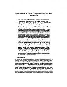
Fig. 1. Third-order Chebyshev bandpass filter [7].
We propose here a multicoarse-model SM algorithm which —very cheap to evaluate assumes the two coarse models: —expensive but much but not necessarily accurate, and more accurate than . could be a circuit equivalent of the microwave structure, could be a model implemented with the same EM simulator as the fine model but using a coarser take less time mesh. We require that a few evaluations of . than a single evaluation of using and a standard SM modeling We enhance methodology [1], [2]. We define an enhanced coarse model as
Fig. 2. Coarse model R
of the third-order Chebyshev filter (Agilent ADS).
TABLE I RESULTS FOR THIRD-ORDER CHEBYSHEV MICROSTRIP FILTER
(5) with parameters
and found as (6)
, are base points, e.g., the so-called while of the star-distribution [6] with center at an optimal solution , i.e., . Typically, the model 1 to 2 1 with being number of base points is between the number of design variables. Optionally, in order to find a better starting point for SM optimization, one can perform one as a coarse model and as a or more SM iterations using fine model and use the optimization outcome as a center of the base set in (6). In practice, we often use one of the special cases of model (5). If necessary, model (5) can be enhanced by other mappings, e.g., a frequency scaling [6]. defined by (5) and (6) is as cheap as , and, at the same in the region determined by the time, almost as accurate as base points . As all coarse models are assumed to be physicsand . based, we expect a good global matching between Our algorithm flow can be described as follows: to find Step 1) optimize ; ; Step 2) choose a base set at base points 1 ; Step 3) evaluate through parameter extraction (6); Step 4) obtain ; Step 5) find 0; Step 6) set ; Step 7) evaluate the fine model to find using (3) and (4); Step 8) obtain the surrogate model Step 9) given and , obtain using (2); Step 10) if the termination condition is not satisfied set and go to Step 7); else END. The algorithm is terminated in the case of convergence or exceeding the user-defined number of iterations. The SM used in (3)–(6) may be of the same or different type, depending on and . the specifics of III. EXAMPLES Consider the third-order Chebyshev bandpass filter [7] shown mm. in Fig. 1. The design parameters are
Fig. 3. Third-order Chebyshev filter: fine model R response (solid line), coarse model R response (dotted line), and enhanced coarse model R response (dashed line) at x .
Other parameters are: 0.4 mm. The fine model is simulated in Sonnet [8] with a fine grid of 0.2 mm 0.02 mm. The simulation time for is about 25 min. 3 dB for 1.8 GHz The design specifications are 2.2 GHz, and 20 dB for 1.0 GHz 1.6 3.0 GHz. is the circuit model impleand 2.4 GHz mented in Agilent ADS [9] (Fig. 2). The evaluation time is is simulated in Sonnet , however, with a about 1.5 s. coarse grid of 2 mm 0.1 mm. The simulation time is about can not be directly used in the SM optimization 1 min. because it is too expensive and available only on a coarse grid. The filter in Fig. 1 was optimized using the standard SM with as well as with the new multicoarse-model coarse model has been created using SM approach. The enhanced as described in Section II with input and frequency SM and ). the star-distribution base set (nine evaluations of model is virtually the same as for , i.e., The evaluation time for 1.5 s. SM optimization used the input SM surrogate enhanced by frequency SM [6]. Table I shows that the multicoarse-model SM produces a better solution than the standard SM with a smaller number of fine model evaluations. Fig. 3 shows the reand at the optimal solution of sponses of , and indicates that the model provides a better match to the fine model than , which explains the better performance of the SM algorithm using . Fig. 4 shows the response at the final solution model found by the new algorithm.
Authorized licensed use limited to: IEEE Xplore. Downloaded on October 15, 2008 at 15:26 from IEEE Xplore. Restrictions apply.
KOZIEL AND BANDLER: SPACE MAPPING WITH MULTIPLE COARSE MODELS
Fig. 4. Third-order Chebyshev filter: final fine model response at the solution obtained with the multicoarse-model SM algorithm.
3
Fig. 7. Open-loop ring resonator bandpass filter: final fine model response at the solution obtained with the multicoarse-model SM algorithm.
TABLE II RESULTS FOR OPEN-LOOP RING RESONATOR FILTER
Fig. 5. Open-loop ring resonator bandpass filter [10].
IV. CONCLUSION A multicoarse-model SM optimization algorithm is presented. The new technique allows us to improve the quality of SM optimization and reduce its computational cost. The robustness of the method is demonstrated through microwave design optimization examples. REFERENCES Fig. 6. Coarse model R
of the open-loop ring resonator filter (Agilent ADS).
Our second example is the open-loop ring resonator bandpass filter [10] shown in Fig. 5. The design parameters are mm. Other parameter values are: 0.6 mm, 0.4 mm. is simulated in FEKO [11] with is about 15 min. The a fine mesh. The simulation time for 3 dB for 2.8 GHz design specifications are 3.2 GHz, and 20 dB for 1.5 GHz 2.5 GHz and 4.5 GHz. is the circuit model implemented 3.5 GHz in Agilent ADS [9] (Fig. 6). The evaluation time is about 1.5 s. is simulated in FEKO, however, with a coarse mesh. The simulation time is 90 s. We optimized the filter in Fig. 5 using the standard SM as well as the new multicoarse-model with coarse model and . The enhanced model SM approach with both has been created using the and with input and frequency SM and random base set (eight evaluations of ). Evaluation time for is almost the same as for model , i.e., 1.5 s. SM optimization used the input SM surrogate enhanced by frequency SM. Table II shows that the multicoarse-model SM algorithms produce a better solution than the standard SM with a smaller number of fine model evaluations. Fig. 7 shows the fine model response at the . final solution
[1] J. W. Bandler, Q. S. Cheng, S. A. Dakroury, A. S. Mohamed, M. H. Bakr, K. Madsen, and J. Søndergaard, “Space mapping: The state of the art,” IEEE Trans. Microw. Theory Tech., vol. 52, no. 1, pp. 337–361, Jan. 2004. [2] S. Koziel, J. W. Bandler, and K. Madsen, “A space mapping framework for engineering optimization: Theory and implementation,” IEEE Trans. Microw. Theory Tech., vol. 54, no. 10, pp. 3721–3730, Oct. 2007. [3] J. V. Morro, H. Esteban, V. E. Boria, C. Bachiller, and A. Coves, “New multimodel ASM technique for the efficient design of complex microwave circuits,” in IEEE MTT-S Int. Dig., Long Beach, CA, 2005, pp. 1613–1616. [4] K. L. Wu, Y. J. Zhao, J. Wang, and M. K. K. Cheng, “An effective dynamic coarse model for optimization design of LTCC RF circuits with aggressive space mapping,” IEEE Trans. Microw. Theory Tech., vol. 52, no. 1, pp. 393–402, Jan. 2004. [5] S. Koziel and J. W. Bandler, “Interpolated coarse models for microwave design optimization with space-mapping,” IEEE Trans. Microw. Theory Tech., vol. 55, no. 8, pp. 1739–1746, Aug. 2007. [6] S. Koziel, J. W. Bandler, A. S. Mohamed, and K. Madsen, “Enhanced surrogate models for statistical design exploiting space mapping technology,” in IEEE MTT-S Int. Dig., Long Beach, CA, Jun. 2005, pp. 1609–1612. [7] J. T. Kuo, S. P. Chen, and M. Jiang, “Parallel-coupled microstrip filters with over-coupled end stages for suppression of spurious responses,” IEEE Microw. Wireless Compon. Lett., vol. 13, no. 10, pp. 440–442, Oct. 2003. [8] em™ version 10.53. Sonnet Software, Inc., North Syracuse, NY, 2007. [9] Agilent ADS, version 2003C. Agilent Technologies, Santa Rosa, CA, 2003. [10] C. Y. Chen and C. Y. Hsu, “A simple and effective method for microstrip dual-band filters design,” IEEE Microw. Wireless Compon. Lett., vol. 16, no. 5, pp. 246–248, May 2006. [11] “FEKO® User’s Manual” EM Software & Systems—S.A. (Pty), Ltd., 2004 [Online]. Available: http://www.feko.info
Authorized licensed use limited to: IEEE Xplore. Downloaded on October 15, 2008 at 15:26 from IEEE Xplore. Restrictions apply.