JOURNAL OF GUIDANCE, CONTROL, AND DYNAMICS Vol. 27, No. 3, May–June 2004
Spacecraft Angular Rate Estimation from Magnetometer Data Only Using an Analytic Predictor Paolo Tortora¤ University of Bologna, 47100 Forl`‡, Italy Yaakov Oshman† Technion—Israel Institute of Technology, 32000 Haifa, Israel and Fabio Santoni‡ University of Rome “La Sapienza,” 00184 Rome, Italy A method is presented for fast estimation of the angular rate of a tumbling spacecraft in a low-Earth orbit from sequential readings of Earth’s magnetic eld. Useful as a backup algorithm in cases of rate gyro malfunctionsor during the initial acquisitionphase, the estimatorconsists of an extended Kalman lter, based on the assumptionthat the inertial geomagnetic eld vector does not signi cantly change during the short sampling time. As the external disturbance torque is neglected, an analytic solution of Euler’s equations can be used in the lter’s propagation phase, allowing a signi cant savings of computation time compared to numerical integration of Euler’s equations. Contrary to most existing angular rate estimators, the spacecraft’s attitude is neither used nor estimated within the proposed algorithm. Moreover, the body-referenced geomagnetic eld observations are not differentiated with respect to time as an external pre ltering procedure but are directly processed by the lter. This processing gives rise to a colored effective measurement noise, which is properly handled via approximate Markov modeling and application of Bryson and Henrikson’s reduced-order ltering theory. A simulation study employing a standard tenth-order International Geomagnetic Reference Field model is presented to demonstrate the performance of the algorithm.
A
I.
Introduction
low-Earth-orbit (LEO) SC during sun eclipse, only Earth magnetic eld observations are available. Several methods have been introduced in the past for angular rate estimation of gyroless SC. Some of them estimate the body angular rates within an attitude/attitude rates estimator, where the measurements are the three components of a body-referenced vector, and make use of deterministic algorithms or ltering techniques.3;4 Thus, in Ref. 3, Psiaki et al. developed an extended Kalman lter (EKF) for the estimation of SC attitude and angular rate from three-axis magnetometer (TAM) readings. The method is based on a known model for the Earth’s magnetic eld, computed with the assumption that the SC ephemeris is well known, takes about an orbit to converge, and yields only coarse accuracy (making it suitable only for emergency modes). In Ref. 4, a two-stage estimator was proposed, in which a slow deterministic algorithm that provides a coarse estimate of the angular rate from magnetometer-only measurements during one satellite orbit is used to initialize a Kalman lter that estimates the orientation and, as a byproduct, the angular rate of the SC. The algorithmuses temporalderivativesof the Earth’s magnetic eld measurements,which are obtained via numerical differentiation. The method is designed to work only in the steadystate, operational mode of the SC and when the angle between the satellite momentum and Earth’s magnetic eld is larger than 15 deg. In other methods,5¡8 SC angular rate components are estimated separately, by the use of either deterministic- or ltering-based algorithms, but always by the use of independently known attitude information. In Refs. 5–7, the attitude matrix is used to rotate the inertial time derivative of the reference vectors into the body frame. The method presentedin Ref. 5 is based on an extensionof the suboptimal interlaced Kalman lter scheme proposed in Ref. 9 and is able to estimate the angular rates from two measured directional vectors, or from a single vector for the relatively short duration of eclipses. In Ref. 6, two estimation methods are presented, based on the ability to decompose the SC dynamics, namely, Euler’s equations including internal torque, into the product of an angular rate-dependent matrix and the angular vector itself. In Ref. 7, a connection is established among various methods, available in the literature, that are aimed at estimating the SC angular rates. It is shown how the
NGULAR rate is a piece of critical information in most implementations of spacecraft (SC) attitude control systems, where it is used for despin, rate damping, and attitude propagation in attitude estimation algorithms.1 Commonly, this information is provided by onboard rate gyros characterized,even those of the highest grade, by their low reliability. A case in point is provided by the Hubble space telescope (HST), which was put on safe hold mode on 13 November 1999 after four of its six world-classrate gyros failed.2 (The HST was brought back to life in December 1999 by the urgent Hubble SM3A servicing mission [space shuttle Space Transportation System (STS-103) mission)]. Coupled with known cases of unexpected satellite thrusters anomalies, which often result in hazardous, tumbling situations (during which the gyros are saturatedby the high SC angular rates), these factors motivate the need for the development of alternative rate estimation algorithms. In addition, small and inexpensivegyrolessSC, which provide solutionsto many of the space community’s current needs, obviously require angular rate estimators that do not rely on the existence of onboard gyros. In high angular rate scenarios, for example, a tumbling SC, or during initial attitude acquisition, the only directional information can be acquired by sun sensors or magnetometers. Moreover, for
Presented as Paper 2000-4240 at the AIAA/AAS Astrodynamics Specialist Conference, Denver, CO, 14–17 August 2000; received 3 October 2002; revision received 8 August 2003; accepted for publication c 2003 by the authors. Published by the 22 September 2003. Copyright ° American Institute of Aeronautics and Astronautics, Inc., with permission. Copies of this paper may be made for personal or internal use, on condition that the copier pay the $10.00 per-copy fee to the Copyright Clearance Center, Inc., 222 Rosewood Drive, Danvers, MA 01923; include the code 0731-5090/04 $10.00 in correspondence with the CCC. ¤ Assistant Professor, II Facolt` a di Ingegneria, Via Fontanelle 40;
[email protected] AIAA. † Associate Professor, Department of Aerospace Engineering,Asher Space Research Inst.;
[email protected]. Associate Fellow AIAA. ‡ Assistant Professor, Scuola di Ingegneria Aerospaziale, Via Eudossiana 18;
[email protected] AIAA. 365
366
TORTORA, OSHMAN, AND SANTONI
so-called derivative approach, where the attitude, in an arbitrary parameterization, is differentiated to relate it to the satellite angular rate, and the estimation approach, where the raw measurements are fed directly into a lter, are both based on an equation relating the attitude, its time derivative, and the angular rate. In Ref. 8, the quaternion is used for attitude representation, and two SC angular rate estimation methods are proposed.The rst uses differentiated quaternion measurements to extract algebraically a noisy estimate of the angular rate vector, which is successively fed into two lters similar to those presented in Ref. 6. In the second, the raw attitude quaternionis fed directly into the lters, whose state vector is augmented to comprise the three angular rate components. A new class of attitude rate estimation algorithms has recently been introduced in Refs. 10–12. In Ref. 11, where the general approach of Ref. 10 is applied to the special case of geomagnetic eld measurements, no attitude knowledge is assumed and sequential readings of the geomagnetic eld direction only are used, with the assumption that this attitude reference vector is xed in inertial space. This renders its estimators completely independent of the SC position and allows their operation without the mechanization of a complicated spherical harmonics model of the Earth’s magnetic eld. Thus, these algorithms are geared toward applications such as detumbling, nutation damping, and momentum management without using rate gyroscopes. Two algorithms are presented in Ref. 11, a coarse, single-frame deterministic batch estimator and a high-accuracyEKF. Although the deterministic batch estimator is less accurate, it nevertheless cannot diverge, and its output can be used to initialize the more sensitive EKF to avoid the latter algorithm’s divergence. The disadvantage of the EKF presented in Ref 11 is that it is based on numerical differentiation of the observed direction vector, which tends to reduce the achievable accuracy due to measurement noise ampli cation. Motivated by Ref. 11, Psiaki and Oshman12 introducedimprovedversionsof both algorithmspresented in Ref. 11. Thus, the deterministic algorithm of Ref. 12 uses a global nonlinear least-squares solver to determine the unknown angular momentum component along the magnetic eld direction, while the EKF is formulated to account for explicitly the normalization constraint on the measured magnetic eld direction vector, and also estimates, in addition to the attitude rate vector, corrections to ve of the six inertia matrix elements, and two error states of the measured magnetic eld direction. However, the deterministic estimator of Ref. 12 shares the same main disadvantage of Ref. 11 in that it, too, is based on explicitly differentiatingthe geomagnetic eld measurements. Motivated by an idea introduced in Ref. 13, where the proposed angular rate lter makes use of an analytical expression relating the temporal derivative of the magnetic eld vector in the body frame to the SC angular rate components, a new gyroless rate estimation method is presented herein. With signi cant improvement on the results presented in an early conference version,14 the new method belongs to the class of methods of Refs. 11 and 12 in that it, too, assumes that the geomagnetic eld vector is constant for the relatively short duration of the estimation process, which renders its estimator independent of the Earth magnetic eld model and does away with model errors, which typically constitute a major error source (of about 300 nT or more). Another characteristicof the estimation method proposed herein is that, similarly to Refs. 10–12, no attitude knowledge is assumed, which makes the algorithm suitable for tumbling and initial acquisition phases. The main contribution of the proposed method is threefold. First, using the extended Kalman ltering methodology, the new algorithm, like its predecessors,also processesdifferentiatednoisy TAM observations.However, the fact that the effectivemeasurement noise is colored is directly addressed in the new algorithm via a colored noise model, to which Bryson and Henrikson’s reduced-order ltering theory15 is applied. Second, the propagation phase of the new estimator is made computationallyef cient by exploiting the observation that, because the external perturbing torque is neglected, one can take advantage of the analytical solution of the rigid-body motion in the absence of external torque in terms of the Jacobian elliptic functions.This strategy allows for signi cant computationaltime
savings with respect to numerical integrationof the Euler rigid-body equations across a sampling interval. Because, as is well known, the state propagation phase of the EKF is the most computationally intensive stage of the algorithm, a signi cant improvement of the lter ef ciency is obtained. As a result, the TAM sampling rate can be increased, thus, improving the estimator’s accuracy even further. Finally, the lter is made robust with respect to uncertainty in the satellite’s matrix of inertia by employing a batch calibration procedure (allowing an almost real-time implementation),which is based on the concept of statistically testing for lter’s consistency.16 The remainder of this paper is organized as follows: In the next section, a brief description of the mathematical model is presented. This is followed by a description of the extended Kalman lter, which includes the proposed analytical time-propagationphase, the measurement model, and the three options considered for handling the effective colored measurement noise. A method to estimate corrections to the matrix of inertia terms, which is based on statistical processing of the innovations sequence, is then presented and discussed.A Monte Carlo simulation study is used to assessstatistically the performance of the new algorithm and to demonstrate its viability via the presentation of numerical example results. Concluding remarks are offered in the last section.
II.
Mathematical Model
The satelliteis assumedto be in tumblingmode, such that there are no internaltorques acting, and the only external torques are the aerodynamic, gravity gradient, and residual magnetic dipole torques. Because the attitude matrix is assumed unknown, the external disturbance torques are represented in the mathematical model by a zero mean stationary process noise. When the common white noise engineeringnotation is used, the vector stochastic differentialequation representing the dynamic model is given by Euler’s equations of motion, P D J ¡1 .¡! £ J!/ C » !
(1)
where ! is the SC angular rate vector, J is the matrix of inertia, and » is a white zero-mean Gaussian process noise with power spectral density Qc . Equation (1) is clearly a nonlinear differentialequation, which can be written in the form xP D f.x; J/ C »
(2)
where x ´ ! is the system’s state vector. The observation model is based on the equation db @b D C!£b dt @t
(3)
where b is the Earth’s magnetic eld vector, db=dt is the (total) temporal derivative of the magnetic eld vector, taken in inertial reference frame, and @b=@t is the (local) temporal derivative taken in the body frame of reference. For most orbits, the left-hand side of Eq. (3), which is generated only by the change in position of the satellite (minimal during the short sampling interval) and by the slow Earth rotation,is negligible relative to both terms on the right-hand side (RHS) of that equation. Therefore, we can set db=dt ¼ 0, which yields @b ¼ ¡! £ b ´ [b£]! @t
(4)
where the cross product matrix corresponding to the magnetic eld vector is de ned as
2
0 1 [b£] D 4 bz ¡b y
¡bz 0 bx
3
by ¡bx 5 0
(5)
367
TORTORA, OSHMAN, AND SANTONI
and the subscripts x, y, and z identify the vector components in body axes. Equation (4) forms the basis for the lter’s observation equation, presented in the sequel. It relates the SC angular velocity to the body-referencedtemporal derivatives of the Earth’s magnetic eld. The approach selected herein for the observation model differs from most of the previously proposed angular rate lters in that it avoids the estimation errors associated with the comparison of the TAM readings to an onboard computed magnetic eld model. As a matter of fact, even when very high-order magnetic eld models are used, a typical residual error of about 1% has to be considered at altitudes typical of low-Earth-orbiting satellites.17 Moreover, because the proposed method makes use only of the body-referenced TAM readings, it does not require independentknowledge of the SC attitude matrix. The estimation error associatedwith the assumptionthat, between two successive samplings, the inertial direction of the Earth’s magnetic eld is constant is discussed in Sec. V.
III.
EKF Design
The proposedestimatorconsistsof a self-initializingEKF. The lter’s state vector x D [!x ! y !z ]T consists of the body-referenced components of the SC angular rate with respect to an inertial reference frame. State Propagation
When a sampling interval of 1t is assumed, the nonlinear state equation (2) can be discretized as xk C 1 D ©k xk C uk
(6)
where ©k is the linearized dynamics state transition matrix and the stationary white process noise sequence uk is distributed as uk » N .0; Q/ with Q » D Qc 1t . Although the time propagation of the state estimate can be performed via numerically integrating Euler’s equations between consecutive sampling times, an improved method is proposed herein, which is based on using the analyticalsolution for rigid-bodymotion in the absence of external torques, in terms of the Jacobian elliptic functions (see Ref. 18). Concisely summarized in the Appendix, the computationalaspects of this well-known solution (for example, Ref. 19) are discussed here, to show how this solution improves the EKF algorithm’s ef ciency and accuracy. Classical algorithms for Jacobian elliptic functionsevaluation are given in Ref. 18, which use the arithmetic-geometricmean (AGM) method, or Landen and Gauss transformations,or series expansion in the parameter m (de ned in the Appendix). An iterative algorithm is described in Ref. 20. The computational burden of these algorithms can be evaluated as the number of oating point operations (FLOPs) required at each step of the iteration. Because the algorithm requires the evaluationof transcendentalfunctionsat each step, the number of FLOPs depends strongly on the processor’s architecture.Whereas in traditionalonboard processorsthe evaluation of transcendental functions is based on series expansions or other iterative methods, requiring a variable number of FLOPs, in most modern processors the evaluation of transcendentaland trigonometric functions is implemented in hardware and can be performed in a single clock interval. Thus, it is assumed here that the evaluation of trigonometricand transcendentalfunctions requires only a single FLOP. The AGM algorithm and the one described in Ref. 20 for the evaluation of Jacobian elliptic functions require 7 FLOPs at each iteration plus 4 FLOPs after convergence. On average, a total of 4 iterations are necessary,20 which means that, on average, 32 FLOPs are needed for the evaluation of the Jacobian elliptic functions. For the evaluationof the projected ahead angular velocity components, 50 FLOPs are needed according to the expressions (A1–A6) given in Appendix. Thus, the analytical propagation requires, on average, 82 FLOPS. This amount is, of course, independent of the propagation time interval. Comparison with numerical integration using a fourth-order Runge–Kutta (RK) method is in order. It was found (see numer-
Table 1
Number of FLOPs for the overall EKF algorithm 1-Hz (sampling rate)
Method
State propagation
Filter
Total
18,000 82
200 200
18,200 282
Numerical Analytical
ical simulations in Sec. V) that a numerical integration step on the order of 10¡3 s is necessary to achieve accuracy comparable to that of the analytical solution over a 1-s time interval. Thus, in practice, 1000 integration steps are required. Because the RK algorithm requires 3 evaluations of the function derivativesat each step, and the evaluation of the RHS of Eq. (1) involves 6 multiplications,one gets a total of about 18,000 FLOPs per 1 time propagationstep using the numerical integration method. Thus, the computational effort for state propagation is reduced by more than two orders of magnitude using the analytical solution proposed earlier. The number of FLOPs involved in the EKF itself, namely, covariance matrix propagationand innovationscalculation, is roughly 200, for a third-order system such as the one at hand. The numerical burden of the overall ltering algorithm is shown in Table 1, which compares numerical and analytical propagation. Using the analytical solution reduces the number of operations to almost 1/60th. The analytical expressions (A1–A6) shown in the Appendix can be further exploitedalso for the computationof the system transition matrix. Equation (A7) shows that the number of FLOPs required for the computation of the rst term of this matrix is about 15, a number that does not include the FLOPS required for the computation of the 2 elliptic integrals of the second kind. For the evaluation of these integrals, an ef cient method is the one proposed by Carlson (see Ref. 20), which requires, on average, about 120 FLOPs. In total, about 255 FLOPs are required for the evaluation of this term and, because the two elliptic integrals (A8) and (A9) are in common among all matrix terms, about 300 FLOPs are needed for the computation of the whole analytical expression of the state transition matrix. However, it is well known (for example, Ref. 21) that, if the state transition matrix is used just for the error covariance matrix time propagation, its accuracy is not crucial. As a matter of fact, because the covariance computation accuracy is not as important as the accuracy of the state propagationacross the sampling interval, a rst-ordernumerical integrationgenerally suf ces for the state transition matrix. This is why the propagation of the error covariance matrix Pk is performed herein using the linearized dynamics state transition matrix, approximated as ©k ¼ I C Fk 1t , where I is the 3 £ 3 identity matrix and the Jacobian matrix Fk is computed as
@f Fk D @x x D xO
2
0
6
D 4. Jz z ¡ Jx x / xO3 =Jyy
. Jx x ¡ Jyy / xO2 =Jz z
.J yy ¡ Jzz / xO3 =Jx x
.J yy ¡ Jzz / xO 2 =Jx x
.Jx x ¡ J yy / xO 1 =Jz z
0
0
3 7
.Jzz ¡ Jx x / xO 1 =J yy 5 (7)
The computation of the state transition matrix using the rst-order approximation shown in Eq. (7) requires only 12 FLOPs, thus, an additional reduction of the computational burden of the whole algorithm is allowed, while incurring practically no loss of overall estimation accuracy. Measurement Model
The TAM reading at time tk is related to the true magnetic eld via bQ k D bk C vk
(8)
where the TAM stationary measurement noise is distributed as vk » N .0; RTAM /
(9)
368
TORTORA, OSHMAN, AND SANTONI
and the covariance RTAM is known. To derive the lter’s measurement equation based on Eq. (4), the body-referenced temporal derivative is approximated using a rst-order backward nite difference, computed using two successive TAM readings. Thus, the observation equation is written as zk D Hk xk C nk
(10)
Applying the matrix inversion lemma to the last two terms on the RHS of Eq. (19), one can easily show that the covariance Rwk is invertible. In principle,one could proceed by augmenting the original EKF’s state vector with the three components of the effective measurement noise, which gives the new state vector as x¯ k D [xkT nkT ]T . The new state transition matrix is then partitioned as
µ
where Hk D [bQ k £ ]1t is the time-varying observation matrix, zk D bQ k ¡ bQ k ¡ 1 is the effectivemeasurement vector, and nk is the effective measurement noise
1
D fI C [xk £] 1t g vk ¡ vk ¡ 1 D Gk .xk / vk ¡ vk ¡ 1
Colored Noise Modeling
A rst-order Markov process is used to model the colored measurement noise ©ck nk ¡ 1
µ
(11)
which can also be viewed as an implied de nition of the statedependent matrix Gk . Notice that the differencing of magnetic eld measurements, which is performed to generate the effective measurement, renders the effective measurement noise colored. Note also that this noise is nonstationaryand state dependent(throughthe matrix Gk /. The state dependency of the measurement noise is handled in an approximate manner, in accord with the usual practice in attitude estimation EKF algorithms, by the substitution of the estimated values of the state for the true values at each time instant. The procedure proposed to handle the colored measurement noise in the context of the proposed EKF is outlined in the sequel.
C wk ¡ 1
(12)
QN D
¡
wk » N 0; Rwk
¢
(13)
To nd the parameters ©ck and Rwk , notice that, from Eq. (12)
¤
£
E nk nkT ¡ 1 D ©ck E nk ¡ 1 nkT ¡ 1
¤
(14)
where E is the mathematicalexpectation.De ne the autocorrelation matrix C.i; j / D E
£
¤
ni nTj
C.k; k/ D Gk RTAM GkT C RTAM
(16a)
C.k ¡ 1; k ¡ 1/ D Gk ¡ 1 RTAM GkT ¡ 1 C RTAM
(16b)
C.k; k ¡ 1/ D ¡RTAM GTk ¡ 1
(16c)
From Eq. (14), and using Eqs. (16b) and (16c), we have ©ck D C.k; k ¡ 1/C.k ¡ 1; k ¡ 1/¡1
¡
D ¡RTAM GTk ¡ 1 Gk ¡ 1 RTAM GTk ¡ 1 C RTAM
£
¤ T
E nk nk D
£
nk ¡ 1 nkT ¡ 1
¤
©k C
D C.k; k/ ¡ ©ck C.k D
Gk RTAM GkT
¡
¡ 1; k
C RTAM ¡
T ¡ 1/©ck
¢¡1
(17)
Rwk
D C.k; k/ ¡ C.k; k
Gk ¡ 1 RTAM
(21)
(23)
and the new measurement noise ´ k D Hk C 1 u k C w k
(24)
is white and normally distributed
¡
¢
R¤k D Hk C 1 QH Tk C 1 C Rwk
´ k » N 0; R¤k ;
(25)
but is correlated with the process noise
£
¤
E uk ´ kT D QH Tk C 1
(26)
To eliminate the cross-correlation between the two noise sequences, the state Eq. (6) is rewritten by adding a term [from Eq. (22)] that is identically zero,
¡
¢
¡
¢
xk C 1 D ©k xk C uk C Tk ³ k ¡ Hk¤ xk ¡ ´ k D ©k ¡ Tk Hk¤ xk C uk ¡ Tk ´ k C Tk ³ k
(27)
When the new process noise
(18)
T ¡ 1/©ck
(19)
(28)
and the modi ed state transition matrix ©¤k D ©k ¡ Tk Hk¤
RTAM GTk ¡ 1
£ Gk ¡ 1 RTAM GTk ¡ 1 C RTAM
03 £ 3
¶
H ¤k D Hk C 1 ©k ¡ ©ck Hk
(29)
are de ned, Eq. (27) can be written as
which, with use of Eqs. (15–17), yields Rwk
03 £ 3 Rwk
u¤k D uk ¡ Tk ´ k
¢¡1
cT
Q
where a modi ed observation matrix has been introduced
we write, with use of Eq. (12)
©ck E
(20)
D Hk C 1 ©k xk C Hk C 1 uk C wk ¡ ©ck Hk xk D Hk¤ xk C ´k (22)
(15)
Using Eqs. (9) and (11) yields
To nd the
¶
³ k D zk C 1 ¡ ©ck zk D Hk C 1 xk C 1 C nk C 1 ¡ ©ck Hk xk ¡ ©ck nk
where the matrix is related to the noise decorrelation time and wk is a zero-mean white sequence, with assumed distribution
covariance Rwk ,
03 £ 3 ©ck
However, the state augmentationprocedure,outlined earlier, generates a singular measurementmodel. One solution,commonly used by estimation practitioners, is to replace the singular measurement noise covariance matrix by a small positive de nite matrix in the Kalman lter mechanization equations. Whereas this solution renders acceptable results in many cases, a much better and more ef cient solution is to implement a reduced-order lter, using Bryson and Henrikson’s method of differencedmeasurements,15 as follows. Note that the estimation of the vector nk is not of interest in this application: A linear combination of zk C 1 and zk not containing nk is formed by
©ck
£
©k 03 £ 3
N k D [Hk I3 £ 3 ] and the prowhile the observationmatrix becomes H cess noise covariance matrix can be written as
nk D vk ¡ vk ¡ 1 ¡ [vk £] 1t ¢ xk
nk D
Nk D ©
xk C 1 D ©¤k xk C u¤k C Tk ³ k
(30)
where the matrix Tk is selected to nullify the cross correlation between the new measurement noise ´ k and the new process noise u¤k ,
£
¤
£
¤
E u¤k ´kT D E .uk ¡ Tk ´ k /´ Tk D QH kT C 1 ¡ Tk R¤k D 0
(31)
TORTORA, OSHMAN, AND SANTONI
369
Solving Eq. (31) for Tk yields
¡ ¢¡1
Tk D QH kT C 1 R¤k
¡
D QH kT C 1 H k C 1 QH kT C 1 C Rwk
¢¡1
(32)
The modi ed state transition matrix is then
¡
©¤k D ©k ¡ QH Tk C 1 Hk C 1 QH Tk C 1 C Rwk
¢¡1 ¡
Hk C 1 ©k ¡ ©ck Hk
¢
(33)
and the new process noise covariance matrix is computed as
£
Q¤k D E u¤k u¤T k
¤
£¡
¡ ¢¡1
D E uk ¡ QH kT C 1 R¤k
´k
¡ ¢¡1
¢¡
¡ ¢¡1
uk ¡ QH kT C 1 R¤k
´k
¢T ¤
D Q ¡ QH kT C 1 R¤k Hk C 1 Q T (34) The differenced measurement given in Eq. (22) and the modi ed matrices de ned in Eqs. (23), (33), and (34) can be used in a standard Kalman lter, where the original dimensions of the state vector, its state transition matrix, and the covariance matrices are preserved. Note that, in practice, the modi ed matrices used in the new lter for the purpose of covariance propagationare approximate because, as already explained, the true state, which appears through Gk , is replaced at each time instant by its estimate. However, the modi ed state propagation equation [Eq. (30)] is not actually used because the analytical procedure proposed in Sec. III is used to propagate the angular velocities between two successive TAM readings.
IV.
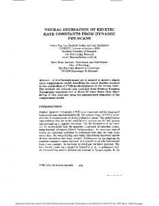
Fig. 1 Three-dimensional plot of the tuning cost function J½ , vs the correction terms ¢Jxx and ¢Jyy .
Batch Calibration of the Inertia Matrix Entries
A rate estimator employing Euler’s equation for its dynamic model might be highly sensitive to mismodeled SC moments of inertia. Past experience14 has shown that an error of a few percent in one diagonal term of the matrix of inertia might even double the estimation errors obtained when a perfect knowledge of the inertia properties is assumed. To alleviate this problem and ensure proper performance of the angular rate lter proposed in Sec. III, a batch procedure, where xed-length blocks of data are processed, is proposed for the calibration of the diagonal entries of the inertia matrix. The calibrated matrix of inertia is written as the sum of a nominal matrix and a correction matrix,
2
Jcal D Jnom C Jcorr
Jx x D4 0 0
0 Jyy 0
3
2
0 1Jx x 0 5C4 0 Jzz 0
0 1 Jyy 0
3
0 05 0 (35)
Corrections to only two of the three diagonal elements of the matrix of inertia are estimated because, if the inertia matrix is diagonal [an assumption needed for the analytical propagation of the state based on the Jacobian elliptic functions (Sec. III)], Euler’s equations become invariant relative to scaling the inertia matrix by a scale factor, yielding that only two diagonal elements are independent. Moreover, in Eq. (35) the off-diagonalentries of the correction matrix have been omitted because it is always possible to formulate the equations of motion in a frame of reference aligned along the principal axes. A procedure to deal with the presence of small nonzero off-diagonal entries in the inertia matrix, representing errors in the computation of the principal axes, is described in the sequel. The proposedmethod is based on the notion of statisticallytesting for lter consistency.16 The particular statistic chosen is the lter’s innovations time-averaged sample autocorrelation. Based on this statistic, the cost function, which is computed and minimized with respect to the two independent terms in the correction matrix, is chosen as
" #¡ 1 K K K X ¡T ¢ X ¡ T ¢X ¡T ¢ 2 J½ D j½.l/j N D ik ik C l ik ik ik C l ik C l (36) k D1 k D1 k D1
Fig. 2 Contour plot of the tuning cost function J½ vs the correction terms ¢Jxx and ¢Jyy .
where ik D ³ k ¡ Hk¤ xˆ k is the innovationssequence and K is an index N large enough to render ½.l/ a normally distributed statistic. The rationale for de ning the cost function (36) is the following. As is well known, the innovations sequence of an optimal (well-tuned) Kalman lter is white and Gaussian distributed. Thus, when l D 1 is set, which correspondsto computing the autocorrelationfunction of the innovations sequence for a time lag of one step, and J½ is minimized over the two-dimensionalspace of feasible inertia matrix correction parameters, the minimum of J½ should be reached where the calibrated inertia matrix is closest to the true inertia matrix. Figure 1 is a three-dimensional plot of the behavior of J½ over the search space (1 Jx x , 1 Jyy / for a set of simulated TAM data (300 s) where the nominal valuesof the diagonalentriesof the matrix of inertia match the true values (J D diagf500; 550; 600g kg ¢ m2 ). Figure 2 is a contour plot of the same data, which shows that the minimum of the cost function is located precisely at (0, 0), and con rms that J½ can be effectively used as a tuning measure for estimating the corrections to the diagonal entries of the inertia matrix. Correspondingly, Fig. 3 shows that the minimum of the root 1 p sum square measure of estimation error 6err D .¾x2 C ¾ y2 C ¾z2 / (where ¾i , i D x; y; z, is the 1-¾ error of the angular rate component along the i axis) is also located near the point (0, 0). The presence of small, unmodeled off-diagonal terms in the matrix of inertia (Jx y , and Jx z and Jyz / can be handled (up to a certain extent) by adjusting the entries of the process noise covariance
370
TORTORA, OSHMAN, AND SANTONI
Table 2
Statistical results of the Monte Carlo simulation study
Angular rate component !x (deg/s) ! y (deg/s) !z (deg/s)
Mean error
1-¾ error
¡0.0011 0.0019 ¡0.0021
0.1199 0.1406 0.1247
Fig. 3 Contour plot of the estimation error measure §err vs the correction terms ¢Jxx and ¢Jyy . Fig. 5 Tuning cost function J½ vs the diagonal term ¾u2 of the covariance matrix Q.
orbit and its initial position and attitude were randomly chosen (not exceeding the altitude of 1000 km), and the magnitude of the spacecraft initial angular velocity was sampled from a uniform distribution over the interval [0, 30] deg/s. In the simulations, the real spacecraft attitude motion was numerically integrated taking into account the aerodynamic, gravity gradient, and residual magnetic dipole torque in the Euler’s equations.The simulated TAM readings were nally generated adding a zero-mean, white Gaussian noise, with a standard deviation of 50 nT, to the magnetic eld vector computed by a tenth-order International Geomagnetic Reference Field model. Perfect Model Knowledge
Fig. 4 Estimation error measure §err vs the diagonal term ¾u2 of the covariance matrix Q.
matrix Q. This 3£3 matrix can be assumed to take the form Q D diagf¾u2 , ¾u2 , ¾u2 g rad2 /s2 because its role is to account for system modeling errors, which are certainly comparable for the three components of the SC angular rate vector. N The innovationsautocorrelationfunction ½.1/, which is available onboardfor the calibrationof Jx x and J yy , can also be used as a tuning statistic to adjust the value of ¾u2 . This method, already proposed in Refs. 22 and 23, is demonstrated numerically by simulating a set of TAM readings of a SC whose matrix of inertia contains offdiagonal terms on the order of 5% of the diagonal ones. These data are processed by a series of identical lters differing only by the value of the process noise covariance matrix Q. Figure 4 shows that the lowest values of the rss estimation error measure 6 err are obtained in a wide range of the scalar ¾u2 . Correspondingly, Fig. 5 shows that the minimum of the cost function J½ is located within the same range, thus, con rming that the residualinformationcontained N in the statistic ½.1/, after estimation of the correction terms 1 Jx x and 1 Jyy , can be used to tune the process noise covariance matrix.
V.
Simulation Study
The performanceof the proposedestimation algorithmsis demonstrated through extensive Monte Carlo simulation studies. The SC
It is initially assumed that the SC matrix of inertia is diagonaland that its entries are exactly known. A Monte Carlo simulation study, consisting of 300 runs, each lasting for 300 s, where the TAM readings are sampled at a frequencyof 2 Hz, is performed to characterize the performance of the algorithm in terms of the ensemble-averaged mean and 1-¾ estimationerror. The matrix of inertiaof the simulated spacecraft is J D diagf500; 550; 600g kg ¢ m2 . The EKF is run in informationform, where the inverse of the error covariance matrix Pk is updated using the inverse of the predicted error covariance matrix P¡ k . This formulation allows initializing the lter with virtually no a priori information about the satellite state by setting the initial value of the inverse covariance (information) ¡1 D ¢ matrix to .P¡ I 10¡8 rad2 /s2 . The lter’s initial estimate is set 0/ D to xˆ ¡ [0 ] rad/s. Because the lter is very robust, due to its in3 £ 1 0 novative measurement model (described in Sec. III), this procedure results in a very rapid lter convergence rate, as has been veri ed for all initial SC angular rates used in a very extensive Monte Carlo simulation study. Notice that, although this feature renders the use of any particular initialization method unnecessary, batch estimation methods (such as the one presented in Ref. 10) can still be used, of course, for this purpose. The statisticalresults of the rst Monte Carlo simulation are summarized in Table 2, which shows that excellent results are obtained by using the measurement differencing approach: The ensembleaveraged mean errors are on the order of 0.001 deg/s, yielding a nearly unbiased lter. Moreover, the 1-¾ errors are very close to the limiting value of 0.12 deg/s, which represents the maximum value (in LEO) of Earth’s magnetic eld inertial rotation rate.
TORTORA, OSHMAN, AND SANTONI
Fig. 6 Angular rate components in a typical run of the rst Monte Carlo simulation.
371
Fig. 8 Performance and computational burden of the RK vs the analytical state propagation.
0.1, 0.05, 0.01, and 0.001 s, respectively.Correspondingly,the number of FLOPs ranges from about 380 to about 18,200, respectively. The dashed line represents the performance of the lter making use of the analytical state propagation proposed in this paper. The circle corresponds to the number of FLOPs required for this lter (about 280). The line has been extended to the right for comparison with the RK integration curve. Figure 8 shows that an EKF using RK propagation can achieve performance comparable to that obtained using the analytical propagation only by employing an integration step of 0.001 s. Remarkably, using the analytical propagation reduces the number of FLOPs from about 2 £ 104 to only 2.8 £ 102 . Uncertain Model Knowledge
Fig. 7 Estimation errors in a typical run of the rst Monte Carlo simulation.
Because this rotation rate is neglected in Eq. (3), it can be stated that the performance achieved by this implementation of the EKF is close to the theoretical limit, dictated by the measurement equation based on Eq. (4). Figures 6 and 7 show the performance of the lter in a typical run, where the initial angular velocity vector is ! D [5:45 ¡ 13:5 10]T ¡deg/s. Analytical Propagation Versus RK Integration
Five additional Monte Carlo simulations, where the SC inertia properties and initial conditions were selected as in the preceding simulation, were performed to compare, in terms of their performance and number of FLOPs, the analytical propagation to RK integration of the state between two sampling times. The EKFs used in all ve Monte Carlo simulations are based on the colored noise model described in Sec. III and the TAM readings were sampled at a frequency of 1 Hz. On the other hand, for the predictor, four of these lters use a standard fourth-order RK integration of the state with different integration steps (ranging from 0.1 to 0.001 s), whereas the fth lter makes use of the analytical state propagation proposed in this paper. For each EKF, the associated process noise covariance matrix Q has been tuned to yield the best estimation performance. The results of these simulations are shown in Fig. 8, where the solid curve represents the performance of the EKFs using RK integration. The symbols on the curve correspond to the various integration steps used by the EKFs: left to right (and top to bottom), these integration steps are
In the next stage of the numerical study, the assumptions of an exactly known and diagonal matrix of inertia were removed to test the real-time calibration procedure proposed in Sec. IV. A long batch (1200 s) of TAM readings is generated at a frequency of 2 Hz, with off-diagonal terms Jx y D Jx z D J yz D 25 kg ¢ m2 added to the nominal, diagonalmatrix of inertia J D diagf500; 550; 600g kg ¢ m2 . The estimator is initialized with wrong values of Jx x and J yy (510 and 560 kg ¢ m2 , respectively), and the procedures to nd the correct 1Jx x , 1 Jyy , and ¾u2 are used in a sequence where blocks of 300 s are processed sequentially. The short length of these blocks allows for an almost real-time implementation of the proposed batch calibration procedure. In each block, only one parameter is adjusted (either 1 Jx x , or 1J yy , or ¾u2 /, running three EKF in parallel, which use different values for the parameter to be estimated. For each of these lters, the cost function J½ is computed, and, according to a simple parabolic t, the estimated parameter value, minimizing J½ , is computed. This optimization procedure is sequential by construction, and its rate of convergence cannot be determined analytically. However, note, in this regard, that the high number of runs performed in several Monte Carlo studies has always shown a convergence rate rapid enough to render the convergence of the whole scheme suf ciently fast for practical purposes. For example, Fig. 9 shows the global performance of the estimator corresponding to adjusting the tuning parameters in the following order: rst 1Jx x , then 1 Jyy , and last ¾u2 . In the rst 300-s block, Jx x converges to the value 501.407 kg ¢ m2 (Fig. 9a), whereas, processing data from 300 to 600 s, the Jyy term converges to the value 548.149 kg ¢ m2 (Fig. 9b). The third block, from 600 to 900 s, serves to tune the diagonal entries of the process noise covariance matrix Q (Fig. 9c). Figure 9d shows the rss estimation error measure 6err , computed independently for each block; after each lter improvement (convergence of Jx x , convergence of J yy , tuning of ¾u2 ), the error measure decreases and its minimum (» 0:758 deg/s) is achieved in the fourth block.
372
TORTORA, OSHMAN, AND SANTONI
¡
!z D
¯
¢
!z0 dn.! p t jm/ C ¹2 ! x0 ! y0 º!3m sn.! p t jm/cn.! p tjm/ 1 ¡ .¹! y0 =!3m /2 sn2 .! p t jm/
(A1)
where !x0 ; ! y0 , and !z0 are the initial values of the angular velocity components and cn, sn, and dn are the Jacobian elliptic functions cosamplitude, senamplitude, and deltamplitude, respectively, with the parameter m given by
a)
mD b)
¡
¢
¡
¢
. Jx x ¡ Jyy / L 2 ¡ 2 Jzz T . Jzz ¡ Jyy / L 2 ¡ 2Jx x T
(A2)
2 with L 2 D Jx2x !2x0 C Jyy !2y0 C Jzz2 !2z0 and T D 12 .Jx x !2x 0 C J yy !2y0 C 2 Jzz !z0 /. The two parameters
µ ¹D
c)
µ ºD
¶ 12
J yy . Jyy ¡ Jx x / Jzz . Jzz ¡ Jx x / J yy .J yy ¡ Jzz / Jx x .Jx x ¡ Jzz /
(A3)
¶ 12 (A4)
depend on the moments of inertia only, whereas
£
2 C ¹2 !2y0 !3m D !z0
d) Fig. 9 Global performance of the real-time calibration of the matrix of inertia.
VI.
Conclusions
A method is presented for fast estimation of the angular rate of a tumbling SC in LEO from sequential readings of Earth’s magnetic eld. The estimator consists of an EKF, which is based on the underlying assumption that the geomagnetic eld vector does not signi cantly change (relative to an inertial frame of reference) during the short sampling time. The analytical solution of rigidbody motion in terms of Jacobian elliptic functions is used in the propagation phase of the lter to improve its accuracy and computational ef ciency. The geomagnetic eld measurements are directly processed by the lter, requiring no external preprocessing differentiation stage. The measurement noise, rendered colored by the differencing involved with the lter’s implementation, is handled via approximate Markov modeling and application of Bryson and Henrikson’s reduced-order ltering theory. A simulation study, which employs a standard tenth-order International Geomagnetic Reference Field model, is presented,showing that the lter can yield 1-¾ errors on the order of 0.12 deg/s. This value is very close to the theoretical limit, dictated by the negligence of the Earth’s magnetic eld inertial rotation rate in the measurement equation. In addition, a batch method (allowing an almost real-time implementation) to calibrate the SC matrix of inertia is proposed, based on statistical processing of the innovations sequence. The calibration method is shown via numerical simulations to be highly effective, not only in estimating correctionsto the diagonal terms of the matrix of inertia, but also in accounting for small, unmodeled, off-diagonal terms, by adjusting the process noise covariance matrix.
Appendix: Analytical Solution of Euler’s Equations The analytical solution of the angular rates of a rigid body in the absence of external torques is19
µ !p D §
.Jzz ¡ J yy /. Jzz ¡ Jx x / Jx x Jyy
(A5)
¶ 12 !3m
(A6)
depend on the initial values of the angular velocity component. In Eq. (A6), the upper sign correspondsto Jx x > Jyy > Jzz and the lower for Jzz > J yy > Jx x . The preceding expressions can be exploited also for the computation of the analytical expression of the state transition matrix for the motion of a rigid body in the absence of external torques. The nine entries of ©.t; 0/, which carry the state from time 0 to time t , require the computation of elliptic integrals of the second kind, E and E 0 . As an example, the full expression of the rst term of the state transition matrix 8.t; 0/11 is 811
@!x !z D D ! x !x0 C ! y ! y0 C @!x0 !z0 ¡
m 1¡m
³
!x ! y ! x0 ! y0 ¡ !z !z 0
´¶
µ
E ¡ E0 ¡ ! p .t ¡ t0 / 1¡m
!z ! y !x 0
(A7)
where
Z ED
¯
dn2 .x/ dx
(A8)
0
and
Z E0 D
¯0
dn2 .x/ dx
(A9)
0
with ¯ and ¯ 0 computed using sn¯ D ! y =!2m , cn¯ D !x =!1m , and sn¯0 D ! y0 =!2m , cn¯0 D !x0 =!1m , and !1m and !2m given by
µ
!x0 cn.! p t jm/ C .º! y0 !z0 =!3m /sn.! p t jm/dn.! p t jm/ 1 ¡ .¹! y0 =!3m /2 sn2 .! p tjm/
!1m D
! y0 cn.! p t jm/dn.! p t jm/ ¡ .!z0 !x 0 =º!3m /sn.! p t jm/ !y D 1 ¡ .¹! y0 =!3m /2 sn2 .! p tjm/
!2m D
!x D
¤ 12
µ
L 2 ¡ 2Jzz T Jx x . Jx x ¡ Jzz / L 2 ¡ 2Jzz T J yy . Jyy ¡ Jzz /
¶ 12 ¶ 12
TORTORA, OSHMAN, AND SANTONI
Acknowledgment Yaakov Oshman gratefully acknowledges the support of the Technion—Israel Institute of Technology’s Asher Space Research Fund.
References 1 Lefferts,
E. J., Markley, F. L., and Shuster, M. D., “Kalman Filtering for Spacecraft Attitude Estimation,” Journal of Guidance, Control, and Dynamics, Vol. 5, No. 5, 1982, pp. 417–429. 2 NASA’s Hubble Project SM3A Web site: URL: http://hubble.gsfc. nasa.gov/servicing-missions/sm3a.html [cited 28 May 2003]. 3 Psiaki, M. L., Martel, F., and Pal, P. K., “Three Axis Attitude Determination via Kalman Filtering of Magnetometer Data,” Journal of Guidance, Control, and Dynamics, Vol. 13, No. 3, 1990, pp. 506–514. 4 Challa, M., Kotaru, S., and Natanson, G., “Magnetometer-Only Attitude and Rate Estimates During the Earth Radiation Budget Satellite 1987 Control Anomaly,” Proceedings of the AIAA Guidance, Navigation and Control Conference, Vol. 2, AIAA, Reston, VA, 1997, pp. 830–840. 5 Azor, R., Bar-Itzhack, I. Y., and Harman, R. R., “Satellite Angular Rate Estimation from Vector Measurements,” Journal of Guidance, Control, and Dynamics, Vol. 21, No. 3, 1998, pp. 450–457. 6 Harman, R. R., and Bar-Itzhack, I. Y., “Pseudolinear and StateDependent Riccati Equation Filters for Angular Rate Estimation,” Journal of Guidance, Control, and Dynamics, Vol. 22, No. 5, 1999, pp. 723–725. 7 Bar-Itzhack, I. Y., “Classi cation of Algorithms for Angular Velocity Estimation,” Journal of Guidance, Control, and Dynamics, Vol. 24, No. 2, 2001, pp. 214–218. 8 Azor, R., Bar-Itzhack, I. Y., Deutschmann, J. K., and Harman, R. R., “Angular Rate Estimation Using Delayed Quaternion Measurements,” Journal of Guidance, Control, and Dynamics, Vol. 24, No. 3, 2001, pp. 436–443. 9 Algrain, M. C., and Saniie, J., “Interlaced Kalman Filtering of 3-D Angular Motion Based on Euler’s Nonlinear Equations,” IEEE Transactions on Aerospace and Electronic Systems, Vol. 30, No. 1, 1994, pp. 175–185. 10 Oshman, Y., and Dellus, F., “Fast Estimation of Spacecraft Angular Velocity Using Sequential Measurements of a Single Directional Vector,” Journal of Spacecraft and Rockets, Vol. 40, No. 2, 2003, pp. 237–247.
373
11 Oshman, Y., and Dellus, F., “Fast Estimation of Spacecraft Angular Velocity from Sequential Geomagnetic Field Observations,” A Collection of the Technical Papers of the AIAA/AAS Astrodynamics Specialists Conference, AIAA, Reston, VA, 2000, pp. 322–330. 12 Psiaki, M. L., and Oshman, Y., “Spacecraft Attitude Rate Estimation from Geomagnetic Field Measurements,” Journal of Guidance, Control and Dynamics, Vol. 26, No. 2, 2003, pp. 244–252. 13 Steyn, W. H., “Chapter 5: Attitude Determination,” A Multi-Mode Attitude Determination and Control System for Small Satellites, Ph.D. Dissertation, Univ. of Stellenbosch, Stellenbosch, South Africa, Dec. 1995. 14 Tortora, P., and Oshman, Y., “Spacecraft Angular Rate Estimation from Magnetometer Data Only,” A Collection of the Technical Papers of the AIAA/AAS Astrodynamics Specialists Conference, AIAA, Reston, VA, 2000, pp. 304–310. 15 Bryson, A. E., Jr., and Henrikson, L. J., “Estimation Using Sampled Data Containing Sequentially Correlated Noise,” Journal of Spacecraft and Rockets, Vol. 5, No. 6, 1968, pp. 662–665. 16 Bar-Shalom, Y., and Fortmann, T. E., “Consistency of State Estimators,” Tracking and Data Association, Academic Press, San Diego, CA, 1988, pp. 70–79. 17 Wertz, J. R. (ed.), “The Earth’s Magnetic Field,” Spacecraft Attitude Determination and Control, Kluwer Academic, Dordrecht, The Netherlands, 1978, p. 118. 18 Abramowitz, M., and Stegun, I. A., Handbook of Mathematical Functions, Dover, New York, 1972, pp. 569–626. 19 Wertz, J. R. (ed.), “Attitude Dynamics,” Spacecraft Attitude Determination and Control, Kluwer Academic, Dordrecht, The Netherlands, 1978, pp. 523–528. 20 Press, W. H., Teukolsky, S. A., Vetterling, W. T., and Flannery, B. P., “Special Functions,” Numerical Recipes in C, 2nd ed., Cambridge Univ. Press, Cambridge, England, U.K., 1992, pp. 261–271. 21 Zarchan, P., and Howard, M., Fundamentals of Kalman Filtering: A Practical Approach, Vol. 190, Progress in Astronautics and Aeronautics, AIAA, New York, 2001, p. 258. 22 Oshman, Y., and Shaviv, I., “Optimal Tuning of a Kalman Filter Using Genetic Algorithms,” AIAA Paper 2000-4558, Aug. 2000. 23 Powell, T. D., “Automated Tuning of an Extended Kalman Filter Using the Downhill Simplex Algorithm,” Journal of Guidance, Control, and Dynamics, Vol. 25, No. 5, 2002, pp. 901–908.