planform studied by Smith and Kroo [4], with an aspect ratio of 7,. NACA 0012 airfoil sections, .... NNX09AJ21G. The author wishes to thank Steve Smith (NASA.
JOURNAL OF AIRCRAFT Vol. 47, No. 4, July–August 2010
Engineering Notes Span Efficiency Prediction Using Adjoint-Driven Mesh Refinement
The Cart3D aerodynamic simulation package [5] is used for this study. Cart3D uses an embedded-boundary multilevel Cartesian mesh in conjunction with a parallel multigrid solver for the threedimensional Euler equations. Forces on the body are computed using surface-pressure integration. Adaptive mesh refinement uses adjoint error estimation to flag cells in the volume grid that contribute the most error to the span efficiency, e � CL2 =�ARCDi . Flagged cells are then iteratively refined through successive flow and adjoint solutions until a preset error tolerance is satisfied. Details on the implementation of the adjoint solver and adaptive mesh refinement scheme are given in [6,7]. For this study, wing geometry is generated parametrically, with the wetted surface being defined by an unstructured triangulation. Both spanwise sections and chordwise vertices are spaced using a cosinesquared clustering, biasing mesh resolution along the airfoil leading and trailing edges and the wing tips. The convergence of spanwise loft lines toward the wing tip quickly leads to degeneracies in the geometry as surface mesh resolution is increased. This issue is typically solved by cropping the wing tips, allowing the loft lines to terminate at a finite edge. The span and, in turn, the aspect ratio, are thus lower than intended, and the likelihood of tip-side-edge wake formation influencing the computed result increases. To eliminate this geometric discrepancy, and suppress flow features not captured by linear theory, a geometry generation tool implementing a novel mesh structure for the wing tips is employed to ensure a consistent surface discretization that models the full span of the wing.
Mathias Wintzer∗ Stanford University, Stanford, California 94305 DOI: 10.2514/1.C031049
I. Introduction
S
TUDIES seeking improvements in wing efficiency through explorations of planform shape and tip geometry can be performed using low-fidelity approaches, such as vortex-lattice [1] and potential-flow [2] methods. Verification using higher-fidelity methods ensures these designs do not exploit the insensitivity of the low-fidelity approach to flow features that may affect the predicted results. The nature of modern subsonic wing design, where financial and environmental pressures demand even incremental gains in efficiency, results in design studies where improvements of 3% are significant and one offering just 1.5% warrants incorporation into a family of production wing designs [3]. Accurate prediction of aerodynamic efficiency is thus critical in order for these small differences to be reliably resolved. The application of an embedded-boundary Cartesian mesh method coupled with a three-dimensional solver for the Euler equations was evaluated for use in high-fidelity verifications of subsonic wing designs. Using handcrafted meshes, reported span efficiencies were substantially lower than expected. Despite repeated trials with a variety of meshes, the highest reported value of span efficiency achieved was still 12% lower than theoretically predicted, and this at significant cost in terms of cells in the mesh. This Note describes the application of the previously-mentioned Cartesian approach with adjoint-based adaptive refinement to predict the span efficiency of an elliptic wing in subsonic inviscid flow. The goal of this study is to evaluate if adjoint-driven mesh refinement will recover the theoretically expected span efficiency value. In addition to providing an important verification study of adaptive mesh refinement, this study characterizes the performance of this approach in terms of accuracy and efficiency as a function of the number of cells in the mesh.
III.
Results
Span efficiencies computed using adjoint-driven mesh refinement are presented for a range of lift coefficients, showing sensitivity of the converged result to the angle of attack �. Results obtained on handcrafted meshes are then compared with a representative adjointadapted case, and meshes produced by each approach are contrasted at equivalent cell counts and levels of refinement. Insights thus gained are applied to the construction of new handcrafted meshes, and a significant improvement in the predicted span efficiency is demonstrated. Finally, recognizing that cell counts on the finest meshes for both handcrafted and adapted meshes are such that direct computation of span efficiency may often be impractical, Richardson extrapolation is used to predict the fine-grid result from a sequence of coarsely adapted grids. All cases were run with a freestream Mach number M1 of 0.3. Grid cells were stretched to an aspect ratio of four in the spanwise direction to maximize resolution in the streamwise direction. The domain outer boundaries were placed at 10 span lengths in the streamwise and planform-normal directions and five span lengths in the spanwise direction. A symmetry plane was placed at the wing root. All adjoint mesh refinements performed used span efficiency as the target functional, and they were started from an initial mesh with a uniform near-body structure containing only 38,000 cells. A surface refinement study showed the converged value of span efficiency increased with tessellation density until the triangle count reached roughly 4 million, after which the value stabilized. The surface definition used to generate the results presented in this Note contains 4.1 million triangles. Handcrafted meshes were constructed using geometry-based refinement indicators [8], which yield high refinement at the body surface in regions of high curvature, along with a gradual coarsening of body-adjacent cells out into the flowfield.
II. Background The wing geometry used for this study is similar to the crescent planform studied by Smith and Kroo [4], with an aspect ratio of 7, NACA 0012 airfoil sections, no twist, and an unswept trailing edge. In their approach, a higher-order surface-panel program was used to represent the geometry, while a vortex-lattice paneling with a wakerelaxation scheme was used to obtain the shape of the force-free wake. This wake shape was then evaluated using a Trefftz plane integral to predict the induced drag. The numerical solution for span efficiency, presented by Smith for this planform, is 0.992. Received 1 April 2010; revision received 10 May 2010; accepted for publication 13 May 2010. Copyright © 2010 by Mathias Wintzer. Published by the American Institute of Aeronautics and Astronautics, Inc., with permission. Copies of this paper may be made for personal or internal use, on condition that the copier pay the $10.00 per-copy fee to the Copyright Clearance Center, Inc., 222 Rosewood Drive, Danvers, MA 01923; include the code 0021-8669/10 and $10.00 in correspondence with the CCC. ∗ Ph.D. Candidate, Department of Aeronautics and Astronautics. Senior Member AIAA.
A.
Sensitivity to Lift Coefficient
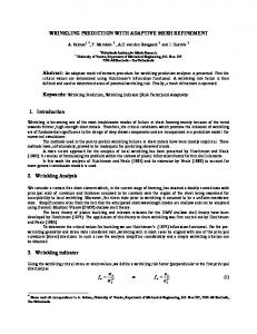
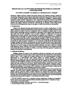
Figure 1 shows the span efficiency variation with the cell count at � � 4, 6, 8, and 10� (CL � 0:36, 0.53, 0.71, and 0.89, respectively). 1468
J. AIRCRAFT, VOL. 47, NO. 4:
1469
ENGINEERING NOTES
1.0
1.00
0.9 0.95 Span Efficiency
Span Efficiency
0.8 0.7 o
=4 o =6 o =8 o = 10
0.6 0.5 0.4
0.90 0.85 Adjoint-refined Handcrafted (initial) Handcrafted (revised) e = 0.992
0.80
0.3 0.2
105
106 Number of Cells
0.75
107
Fig. 1 Span efficiency convergence with increasing cell count at � � 4, 6, 8, and 10� (CL � 0:36, 0.53, 0.71, and 0.89, respectively).
106
107 Number of Cells
108
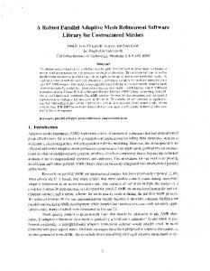
Fig. 3 Comparison of results obtained using adapted and handcrafted grids. The revised handcrafted meshes are modeled on the adapted meshes. Cases shown are run at � � 6� .
o
=4 o =6 o =8 o = 10
Error Estimate
10-1
10-2 105
106 Number of Cells
107
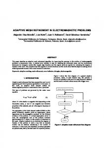
Fig. 2 Estimated error in functional with increasing cell count at � � 4, 6, 8, and 10� (CL � 0:36, 0.53, 0.71, and 0.89, respectively).
The rate of convergence increases with CL until the number of cells reaches roughly 10 million cells. At this point, span efficiency values predicted for the 6� and above cases are in agreement, while the 4� case is both slower to converge and does so to a slightly lower e. A case run at � � 3� (not shown) confirmed that this lagging trend continues as the angle of attack is reduced. This behavior is attributed to the large discretization error present in the coarse (initial) meshes leading to excessive artificial dissipation that, in turn, manifests as excess drag, shifting the efficiency curve downward. The adjointdriven mesh refinement process provides an estimate of the error level at every cycle, and Fig. 2 shows the change in the estimated functional error as the mesh refinement proceeds. The increase in the error level during early cycles is due to the grid coarseness, which hampers resolution of the extent of the discretization error present in the volume grid. As CL is increased, slightly lower levels of error are observed throughout the majority of the refinement process. The span efficiency and corresponding adjoint-estimated error at each � condition are summarized in Table 1. B.
Comparison with Handcrafted Meshes
Figure 3 plots the span efficiency initially obtained using handcrafted meshes. Each doubling of the cell count includes an increase in the maximum grid refinement level. This offers some gains at first, but subsequent grid refinements yield minimal Table 1 Summary of span efficiency results computed using adjoint-driven mesh adaptation �
CL
e
Error estimate, %
4.0 6.0 8.0 10.0
0.36 0.53 0.71 0.89
0.988 0.992 0.992 0.991
2.6 1.8 1.6 1.5
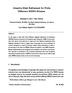
Fig. 4 Midspan cut of the handcrafted mesh. Mesh contains roughly 15.6 million cells, and predicted span efficiency is 0.874 at � � 6� . Lowerleft subfigure shows the forward 10% of the airfoil, while the lower-right subfigure shows the aft 10%.
increases in span efficiency. In contrast with values predicted by the adjoint-driven mesh adaptation at the same flow condition (� � 6� and M1 � 0:3), the computed span efficiency is, at best, 12% lower. A midspan cut of the handcrafted mesh, containing 15.6 million cells, is shown in Fig. 4. Predicted span efficiency for this case is 0.874. The finest cells are concentrated around the leading and trailing edges to capture the deceleration and acceleration of the flow at the stagnation points. Cells are then rapidly coarsened, moving out from the body into the freestream to keep the total cell count manageable. The structure for the adapted mesh, shown in Fig. 5, is substantially different. With a comparable number of cells, this mesh predicts a span efficiency of 0.990. While the body-adjacent cell structure depicted in the subfigures is qualitatively similar, the nearfield mesh is significantly more complex. Attention is called in particular to the visible extension of the mesh along the leading and trailing stagnation lines, and the additional detail above the airfoil, to better resolve acceleration of the flow on the upper surface of the airfoil. Although the total cell counts are similar, the adjoint-driven process trades high refinement in the body-adjacent cells for more extensive grid refinement in the near field, effectively and efficiently capturing the behavior of the flow about the wing. Based on these observations, the handcrafted meshes were revised to more gradually taper from one level of refinement to another, adding grid resolution in the near field. Results are identified as revised in Fig. 3 and, while the highest reported span efficiency of 0.989 compares favorably with the adapted mesh value, twice as many cells are used in the handcrafted mesh. A planform view of the adapted fine mesh in the region of the wing is shown in Fig. 6. Mesh refinement captures both the upstream and
1470
J. AIRCRAFT, VOL. 47, NO. 4:
ENGINEERING NOTES
Table 2 Comparison of span efficiency results computed using adjoint-driven mesh adaptation and Richardson extrapolation �
CL
e
Extrapolated e
4.0 6.0 8.0 10.0
0.36 0.53 0.71 0.89
0.988 0.992 0.992 0.991
0.979 1.00 1.01 1.01
IV. Conclusions
Fig. 5 Midspan cut of the adapted mesh at cycle 13. Mesh contains roughly 15.6 million cells, and predicted span efficiency is 0.990 at � � 6� . Lower-left subfigure shows the forward 10% of the airfoil, while the lower-right subfigure shows the aft 10%.
Span efficiencies predicted using the adjoint-driven scheme were shown to compare favorably with the result of [4] and classical linear theory. In addition, the adjoint-driven method provided a means of characterizing the accuracy of the predicted solution, consistent with the numerical approach used. Inspection of adapted mesh structures revealed features that, when applied to handcrafted meshes, enabled recovery of the theoretically expected result. In a constrained environment, where adaptation to the fine-grid solution is impractical, extrapolation to the fine-grid result using a modestly adapted grid was shown to agree with the fine-grid result to within its estimated error. These results indicate that, while span efficiency prediction using handcrafted meshes is possible, the adjoint-driven approach is preferable, enabling efficient, automated prediction that does not depend on any foreknowledge of the necessary mesh structure to ensure high accuracy.
Acknowledgments The author gratefully acknowledges support from NASA grant NNX09AJ21G. The author wishes to thank Steve Smith (NASA Ames Research Center) and Ilan Kroo (Stanford University) for their invaluable input during the course of this study. The author also wishes to thank Marian Nemec (ELORET Corporation) and Michael Aftosmis (NASA Ames Research Center) for sharing their expertise with the adaptation and simulation tools used during this study and many interesting discussions. Fig. 6 Planform view of the final adapted mesh for the � � 6� (CL � 0:53) case; inset depicts the initial mesh. Meshes contain 24 million and 38,000 cells, respectively.
downstream influence of the tip vortex on the span efficiency. This streamwise mesh structure is missed by the initial hand mesh construction and only partially approximated by the revised handcrafted meshes. C.
Coarse-Grid Extrapolation
Richardson extrapolation is used to study the convergence of span efficiency as the mesh is refined. The continuum value of span efficiency e� can be extrapolated using the relationship � � 1 p ������ � e� e�k p 3 Nc
(1)
where e is the computed span efficiency, Nc is the number of grid cells, p is the order of convergence, and k is the slope. Based p������ on studies in [5,6], p � 2 for this approach. The parameter �1= 3 Nc �p is a measure of cell size. Using data from cycle 3, corresponding to the peak in the error curves, to cycle 8, where the adapted grids contain roughly 2.3 million cells; the continuum functional values were extrapolated using a linear least-squares fit. Table 2 compares the coarse-grid-extrapolated span efficiencies with those computed directly from an adapted fine grid.
References [1] Ning, S. A., and Kroo, I. M., “Tip Extensions, Winglets, and C-Wings: Conceptual Design and Optimization,” 26th AIAA Applied Aerodynamics Conference, AIAA Paper 2008-7052, Aug. 2008. [2] Smith, S. C., “A Computational and Experimental Study of Nonlinear Aspects of Induced Drag,” NASA Ames Research Center, TP 3598, Moffett Field, CA, Feb. 1996. [3] Kroo, I. M., “Drag Due to Lift: Concepts for Prediction and Reduction,” Annual Review of Fluid Mechanics, Vol. 33, No. 1, 2001, pp. 587–617. doi:10.1146/annurev.fluid.33.1.587 [4] Smith, S. C., and Kroo, I. M., “Computation of Induced Drag for Elliptical and Crescent-Shaped Wings,” Journal of Aircraft, Vol. 30, No. 4, 1993, pp. 446–452. doi:10.2514/3.46365 [5] Aftosmis, M. J., and Berger, M. J., “Multilevel Error Estimation and Adaptive H-Refinement for Cartesian Meshes with Embedded Boundaries,” 40th Aerospace Sciences Meeting and Exhibit, AIAA Paper 2002-0863, Jan. 2002. [6] Nemec, M., and Aftosmis, M. J., “Adjoint Sensitivity Computations for an Embedded-Boundary Cartesian Mesh Method,” Journal of Computational Physics, Vol. 227, No. 4, 2008, pp. 2724–2742. doi:10.1016/j.jcp.2007.11.018 [7] Nemec, M., and Aftosmis, M. J., “Adjoint Error Estimation and Adaptive Refinement for Embedded-Boundary Cartesian Meshes,” 18th AIAA Computational Fluid Dynamics Conference, AIAA Paper 2007-4187, June 2007. [8] Aftosmis, M. J., Berger, M. J., and Melton, J. E., “Robust and Efficient Cartesian Mesh Generation for Component-Based Geometry,” AIAA Journal, Vol. 36, No. 6, June 1998, pp. 952–960. doi:10.2514/2.464