Klein R. et al. (Eds.), Computer Science in Perspective, LNCS 2598, 2003, pp. 216-230
Spatial Data Management for Virtual Product Development Hans-Peter Kriegel*, Martin Pfeifle*, Marco Pötke**, Matthias Renz*, Thomas Seidl*** University of Munich, Institute for Computer Science http://www.dbs.informatik.uni-muenchen.de *{kriegel, pfeifle, renz}@dbs.informatik.uni-muenchen.de **
[email protected] ***
[email protected]
Abstract: In the automotive and aerospace industry, millions of technical documents are generated during the development of complex engineering products. Particularly, the universal application of Computer Aided Design (CAD) from the very first design to the final documentation created the need for transactional, concurrent, reliable, and secure data management. The huge underlying CAD databases, occupying terabytes of distributed secondary and tertiary storage, are typically stored and referenced in Engineering Data Management systems (EDM) and organized by means of hierarchical product structures. Although most CAD files represent spatial objects or contain spatially related data, existing EDM systems do not efficiently support the evaluation of spatial predicates. In this paper, we introduce spatial database technology into the file-based world of CAD. As we integrate 3D spatial data management into standard object-relational database systems, the required support for data independence, transactions, recovery, and interoperability can be achieved. Geometric primitives, transformations, and operations on threedimensional engineering data will be presented which are vital contributions to spatial data management for CAD databases. Furthermore, we will present an effective and efficient approach to spatially index CAD data by using the concepts of object-relational database systems and the techniques of relational access methods. The presented techniques are assembled to a complete system architecture for the Database Integration of Virtual Engineering (DIVE). By using relational storage structures, the DIVE system provides three-dimensional spatial data management within a commercial database system. The spatial data management and the query processor is fully embedded into the Oracle8i server and has been evaluated in an industrial environment. Spatial queries on large databases are performed at interactive response times.
1 Introduction In mechanical engineering, three-dimensional Computer Aided Design (CAD) is employed throughout the entire development process. From the early design phases to the final production of cars, airplanes, ships, or space stations, thousands to millions of CAD files and many more associated documents including technical illustrations and business documents are generated. Most of this data comprises spatial product components or spatially related content. Recently, new CAD applications have emerged to support virtual engineering on this data, i.e. the evaluation of product characteristics without building even a single physical prototype. Typical applications include the digital mock-up (DMU) [BKP98] or haptic rendering of product configurations [MPT99]. Engineering Data Management (EDM) systems organize the huge underlying CAD databases by means of hierarchical product structures. Thus, structural queries as “retrieve all documents that refer to the current version of the braking system” are efficiently supported. If we look at CAD databases from a spatial point of view, each instance of a part occupies a specific region in the three-dimensional product space (cf. Fig. 1). Together, all parts of a given product version and variant thereby represent a virtual prototype of the constructed geometry. Virtual engineering requires access to this product space by spatial predicates in order to “find all parts intersecting a specific query volume” or to “find all parts in the immediate spatial neighborhood of the disk brake”. Unfortunately, the inclusion of the respective spatial predicates is not supported efficiently by common, structure-related EDM systems. This paper is organized as follows: In the next section, we shortly review the common file-based organization of spatial CAD data and describe three important industrial applications which benefit from a relational index. In section 3 we discuss the transformation and approximation of high-resolution CAD data originating from heterogeneous sources. In section 4 we shortly review the RI-tree, which is an efficient index structure for intervals. Finally, in the last section we present an architecture for the Database Integration of Virtual Engineering (DIVE) for existing Engineering Data Management systems (EDM).
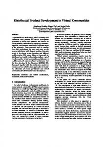
2 Spatial Engineering In the file-based world of CAD applications, the huge amount of spatial data is typically organized by hierarchical product structures which efficiently support selections
Fig.1: Virtual prototype of a car.
with respect to variants, versions, and functions of components. In this section, we propose the integration of spatial data management into existing EDM systems. Existing EDM systems are based on fully-fledged object-relational database servers. They organize and synchronize concurrent access to the CAD data of an engineering product. The distributed CAD files are linked to global product structures which allow a hierarchical view on the many possible product configurations emerging from the various versions and variants created for each component [Pö98]. Although the EDM system maintains a consistent knowledge about the storage location of each native CAD file, only a few spatial properties, including the position and bounding box of the respective part in the product space, are immediately accessible. But many applications of virtual engineering require a more fine-grained spatial selection. Thus, the EDM system has to be extended by a high-resolution representation of the product geometry which is organized by spatial indexes in order to achieve interactive response times.
2.1 Integrated Spatial Data Management In order to supplement an existing EDM system with spatial representation and selection of CAD data, one of the most important components required from the underlying object-relational database system is a three-dimensional spatial index structure. By introducing an efficient spatial access path besides the existing support for structural evaluations, we can achieve an integrated database management for both, spatial and nonspatial engineering data. Relational access methods on spatial databases can be seamlessly integrated into the object-relational data model while preserving the functionality and performance of the built-in transaction semantics, concurrency control, recovery services, and security. The following section discusses realistic applications to illustrate the practical impact of the proposed concepts.
2.2 Industrial Applications We present three industrial applications of virtual engineering which immediately benefit from a relational index on spatial CAD data. We have analyzed and evaluated them in cooperation with partners in the automotive and aerospace industry, including the Volkswagen AG, Wolfsburg, the German Aerospace Center DLR e.V., Oberpfaffenhofen, and the Boeing Company, Seattle. Digital Mock-up of Prototypes. In the car industry, late engineering changes caused by problems with fit, appearance or shape of parts already account for 20-50 percent of the total die cost [CF91]. Therefore, tools for the digital mock-up (DMU) of engineering products have been developed to enable a fast and early detection of colliding parts, purely based on the available digital information. Unfortunately, these systems typically operate in main-memory and are not capable of handling more than a few hundred parts. They require as input a small, well-assembled list of the CAD files to be examined. With the traditional file-based approach, each user has to select these files manually. This can
a) Box volume query
b) Collision query
Fig.2: Spatial queries on CAD data.
take hours or even days of preprocessing time, since the parts may be generated on different CAD systems, spread over many file servers and are managed by a variety of users [BKP98]. In a concurrent engineering process, several cross-functional project teams may be recruited from different departments, including engineering, production, and quality assurance to develop their own parts as a contribution to the whole product. However, the team working on section 12B of an airplane may not want to mark the location and the format of each single CAD file of the adjacent sections 12A and 12C. In order to do a quick check of fit or appearance, they are only interested in the colliding parts. Moreover, the internet is gaining in importance for industrial file exchange. Engineers, working in the United States, may want to upload their latest component design to the CAD database of their European customer in order to perform interference checks. Thus, they need a fast and comfortable DMU interface to the EDM system. Fig. 2 depicts two typical spatial queries on a three-dimensional product space, retrieving the parts intersecting a given box volume (box volume query), and detecting the parts colliding with the geometry of a query part (collision query). A spatial filter for DMU-related queries on huge CAD databases is easily implemented by a spatial access method which determines a tight superset of the parts qualifying for the query condition. Then, the computationally intensive query refinement on the resulting candidates, including the accurate evaluation of intersection regions (cf. Fig. 2a), can be delegated to an appropriate main memorybased CAD tool. Haptic Rendering. The modern transition from the physical to the digital mock-up has exacerbated the well-known problem of simulating real-world engineering and maintenance tasks. Therefore, many approaches have been developed to emulate the physical constraints of natural surfaces, including the computation of force feedback, to capture the contact with virtual objects and to prevent parts and tools from interpenetrating [GLM96] [LSW99] [MPT99]. Fig. 3a [Re00] depicts a common haptic device to transfer
a) Haptic device b) Virtual environment Fig.3: Sample scenario for haptic rendering.
Fig.4: Virtual environment of the International Space Station.
the computed force feedback onto a data glove. The simulated environment, along with the force vectors, is visualized in Fig. 3b. By using this combination of haptic algorithms and hardware, a realistic force loop between the acting individual and the virtual scene can be achieved. Naturally, a real-time computation of haptic rendering requires the affected spatial objects to reside in main-memory. In order to perform haptic simulations on a large scale environment comprising millions of parts, a careful selection and efficient prefetching of the spatially surrounding parts is indispensable. Fig. 4 illustrates the complexity of usual virtual environments by the example of the International Space Station (ISS). In order to simulate and evaluate maintenance tasks, e.g. performed by autonomous robots, an index-based prefetching of persistent spatial objects can be coupled with real-time haptic rendering [Re02]. Spatial Document Management. During the development, documentation, and maintenance of complex engineering products, many other files besides the geometric surfaces and solids of product components are generated and updated. Most of this data can also be referenced by spatial keys in the three-dimensional product space (cf. Fig. 5), including kinematic envelopes which represent moving parts in any possible situation or spatial clearance constraints to reserve unoccupied regions, e.g. the minimal volume of passenger cabins or free space for air circulation around hot parts. Furthermore, technical illustrations, evaluation reports or even plain business data like cost accounting or sales reports for specific product components can be spatially referenced. Structurally referencing such documents can become very laborious. For example, the meeting minutes concerning the design of a specific detail of a product may affect many different components. Spatial referencing provides a solution by simply attaching the meeting minutes to
a) Parts
e) Business
b) Envelopes
d) Illustrations c) Clearances
Fig.5: Spatial referencing of engineering documents.
a spatial key created for the region of interest. A very intuitive query could be: “retrieve all meeting minutes of the previous month concerning the spatial region between parts A and B”. Such queries can be efficiently supported by spatial indexes.
3 Operations on Spatial Engineering Data We consider an engineering product as a collection of individual, three-dimensional parts, while each part potentially represents a complex and intricate geometric shape. The original surfaces and solids are designed at a very high precision. In order to cope with the demands of accurate geometric modeling, highly specialized CAD applications are employed, using different data primitives and native encodings for spatial data. For our spatial database, we defined a set of universal representations which can be derived from any native geometric surface and solid. The supported geometric data models include triangle meshes for visualization and interference detection, voxel sets and interval sequences as conservative approximations for spatial keys, and dynamic point shells to enable real-time haptic rendering.
3.1 Triangle Meshes Accurate representations of CAD surfaces are typically implemented by parametric bicubic surfaces, including Hermite, Bézier, and B-spline patches. For many operations, such as graphical display or the efficient computation of surface intersections, these parametric representations are too complex [MH99]. As a solution, approximative polygon (e.g. triangle) meshes can be derived from the accurate surface representation. These triangle meshes allow for an efficient and interactive display of complex objects, for instance by means of VRML encoded files, and serve as an ideal input for the computation of spatial interference. For the digital mock-up (DMU), collision queries are a very important database primitive. In the following, we assume a multi-step query processor which retrieves a candidate part S possibly colliding with a query part Q. In order to refine such collision queries, a fine-grained spatial interference detection between Q and S can be implemented on their triangle meshes. We distinguish three actions for interference detection [MH99]: collision detection, collision determination, and collision response: Collision detection: This basic interference check simply detects if the query part Q and a stored part S collide. Thus, collision detection can be regarded as a geometric intersection join of the triangle sets for S and Q which already terminates after the first intersecting triangle pair has been found. Collision determination: The actual intersection regions between a query part and a stored part are computed. In contrast to the collision detection, all intersecting triangle pairs and their intersection segments have to be reported by the intersection join.
a) Triangulated surface
b) Voxelized surface
Fig.6: Scan conversion on a triangulated surface.
Collision response: Determines the actions to be taken in consequence of a positive collision detection or determination. In our case of a spatial database for virtual engineering, a textual or visual feedback on the interfering parts and, if computed, the intersection lines seems to be appropriate. 3.2 Interval Sequences The Relational Interval Tree (RI-tree), as presented in section 4, significantly outperforms competing techniques with respect to usability and performance. In order to employ the RI-tree as a spatial engine for our CAD database, we propose a conversion pipeline to transform the geometry of each single CAD part to an interval sequence by means of voxelization. A basic algorithm for the 3D scan-conversion of polygons into a voxel-based occupancy map has been proposed by Kaufmann [Ka87]. Similar to the well-known 2D scan-conversion technique, the runtime complexity to voxelize a 3D polygon is O(n), where n is the number of generated voxels. If we apply this conversion to the given triangle mesh of a CAD object (cf. Fig. 6a), a conservative approximation of the part surface is produced (cf. Fig. 6b). In the following, we assume a uniform threedimensional voxel grid covering the global product space. If a triangle mesh is derived from an originally solid object, each triangle can be supplemented with a normal vector to discriminate the interior from the exterior space. Thus, not only surfaces, but also solids could potentially be modeled by triangle meshes. Unfortunately, triangle meshes generated by most faceters contain geometric and topological inconsistencies, including overlapping triangles and tiny gaps on the surface. Thus, a robust reconstruction of the original interior becomes very laborious. Therefore, we follow the common approach to voxelize the triangle mesh of a solid object first (cf. Fig. 7a), which yields a consistent representation of the object surface. Next, we apply a
b) Filled exterior a) Voxelized surface c) Inverted result Fig.7: Filling a closed voxelized surface.
Hilbert-order Z-order lexicographic order Fig.8: Examples of space-filling curves in the two-dimensional case
3D flood-fill algorithm [Fo00] to compute the exterior voxels of the object (cf. Fig. 7b), and thus, determine the outermost boundary voxels of the solid. We restrict the flood-fill to the bounding box of the object, enlarged by one voxel in each direction. The initial fill seed is placed at the boundary of this enlarged bounding box. In the final step, we simply declare all voxels as interior which are neither boundary nor exterior voxels (cf. Fig. 7c). In consequence, we obtain a volumetric reconstruction of the original solid, marking any voxels behind the outermost surface as interior. The above algorithm has a runtime complexity of O(b), where b is the number of voxels in the enlarged bounding box. The derived voxel set of an arbitrary surface or solid represents a consistent input for computing interval sequences. The voxels correspond to cells of a grid, covering the complete data space. By means of space filling curves, each cell of the grid can be encoded by a single integer number, and thus an extended object is represented by a set of integers. Most of these space filling curves achieve good spatial clustering properties. Therefore, cells in close spatial proximity are encoded by similar integers or, putting it another way, contiguous integers encode cells in close spatial neighborhood. Examples for space filling curves include Hilbert-, Z-, and the lexicographic-order, depicted in Fig. 8. The Hilbert-order generates the minimum number of intervals per object [Ja90] [FR89] but unfortunately, it is the most complex linear order. Taking redundancy and complexity into consideration, the Z-order seems to be the best solution. Therefore, it will be used throughout the rest of this paper. Voxels can be grouped together to Object Interval Sequences, such that an extended object can be represented by some continuous ranges of numbers. Thereby, the storage of spatial CAD objects as well as box volume queries, collision queries, and clearance queries can be efficiently supported by the RI-tree. Fig. 9 summarizes the complete transformation process from triangle meshes over voxel sets to interval sequences. The major advantage of this conversion pipeline lies in the fact that it can be universally applied for
a) Triangle mesh b) Voxel set c) Interval sequence Fig.9: Conversion pipeline from triangulated surfaces to interval sequences.
any CAD system comprising a triangle faceter. The restriction of the possible input to triangle meshes naturally yields a suboptimal processing cost, but significantly reduces the interface complexity of our spatial CAD database.
3.3 Point Shells In order to achieve real-time interference detection for moving objects, two properties of the geometric representation are of major importance: (1) efficient geometric transformations, e.g. translation and rotation, and (2) efficient intersection tests. Triangle meshes naturally qualify for (1), as their topology is invariant to geometric transformations of triangle vertices. If consecutive triangle intersection joins rely on hierarchical indexes as OBBTrees or k-DOPTrees [GLM96][Kl98], criterion (2) is principally fulfilled as well. In the case of haptic rendering, a constant refresh rate of at least 1,000 Hz has to be guaranteed to create a realistic force feedback [MPT99]. The performance of triangle-based intersections is still too slow and unstable for this purpose [Pö01]. For voxel sets, on the other hand, intersections can be computed very efficiently by using bitmap operations, thus fulfilling (2) even for the high requirements of haptic rendering. But a voxelized representation of a moving object has to be recomputed for each single position and orientation, and therefore fails for (1). As a solution, McNeely, Puterbaugh and Troy [MPT99] have proposed the Voxmap PointShell technique (VPS), combining the high performance of voxel intersections with an efficient representation for dynamic objects. Thus, both criteria (1) and (2) are fulfilled for real-time haptic rendering of objects moving in a static environment. As the basic idea of VPS, point shells representing the moving objects are checked for interference with a voxelized environment. We compute the point shell for a moving object in four steps: first, a triangle mesh for the object surface is derived (cf. Fig. 10a). Next, we voxelize the resulting mesh (Fig. 10b) and get a first approximation of the point shell by the center points of all boundary voxels (Fig. 10c). As an extension to the original algorithm, we further increase the accuracy of the point shell in a final step to generate a smoother surface representation as proposed in [Re01]: within each boundary voxel we interpolate the closest surface point to the voxel center (cf. Fig. 10d). As a result, we obtain a set of accurate surface points which are uniformly distributed over the surface of the moving object. In addition, the respective normal vector n(p) is computed for each surface point p, pointing inwards. The set of all resulting surface points along with the normal vectors comprises the point shell. Its accuracy is determined by the resolution of
a) Triangulation
b) Voxelization
c) Center points
Fig.10: Computation of point shells.
d) Surface points
T(p, v)
n(p) p
static surface point shell
p v
v
d>0
d≤0
a) No surface interpenetration
b) Surface interpenetration
Fig.11: Computation of force feedback.
the underlying voxel grid and the triangle mesh. In the example of Fig. 10, the sphere represents a fingertip of the hand depicted in Fig. 3b. Due to the haptic device of Fig. 3a, it is physically exposed to the computed force feedback. A practical setup for VPS comprises a voxelized representation of the static environment and a point shell for the moving object. Therefore, the interference detection is reduced to point-voxel intersections which can be computed by a plain three-dimensional address computation for each point. If the resolution of the voxel grid and the dynamic point shell are chosen properly, point-voxel intersections are guaranteed to occur in the case of a surface interpenetration. Fig. 11 [MPT99] depicts a local interference of a surface point p of the dynamic point shell with a voxel v of the static environment. In this case, the depth of interpenetration d is calculated as the distance from p to the tangent plane T(p, v). This tangent plane is dynamically constructed to pass through the center of v and to have n(p) as normal vector. If p has not penetrated below the tangent plane, i.e. in the direction to the interior of the static object, we obtain d ≤ 0 and produce no local force feedback (cf. Fig. 11a). According to Hooke’s law, the contact force is proportional to d > 0 (cf. Fig. 11b), and the force direction is determined by n(p). Both determine the force vector of this local interpenetration. The average over all local force vector in the point shell is transferred to the haptic device to exert the resulting force feedback. In the haptic exploration scene depicted in Fig. 12 the average force vectors for each fingertip are visualized as arrows pointing towards the effective contact force.
Fig.12: Display of the contact forces in a haptic exploration scene.
4 The Relational Interval Tree as Efficient Spatial Access Method The Relational Interval Tree (RI-tree) [KPS00] is an application of extensible indexing for interval data. Based on the relational model, intervals can be stored, updated and queried with an optimal complexity. In this section, we briefly review the basic concepts of the RI-tree. The RI-tree strictly follows the paradigm of relational storage structures since its implementation is restricted to (procedural) SQL and does not assume any lower level interfaces. In particular, the built-in index structures of a DBMS are used as they are, and no intrusive augmentations or modifications of the database kernel are required. The conceptual structure of the RI-tree is based on a virtual binary tree of height h which acts as a backbone over the range [0…2h–1] of potential interval bounds. Traversals are performed purely arithmetically by starting at the root value 2h and proceeding in positive or negative steps of decreasing length 2h–i, thus reaching any desired value of the data space in O(h) time. This backbone structure is not materialized, and only the root value 2h is stored persistently in a metadata tuple. For the relational storage of intervals, the nodes of the tree are used as artificial key values: Each interval is assigned to a fork node, i.e. the first intersected node when descending the tree from the root node down to the interval location. An instance of the RI-tree consists of two relational indexes which in an extensible indexing environment are at best managed as index-organized tables. The indexes then obey the relational schema lowerIndex (node, lower, id) and upperIndex (node, upper, id) and store the artificial fork node value node, the bounds lower and upper and the id of each interval. Any interval is represented by exactly one entry in each of the two indexes and, thus, O(n/b) disk blocks of size b suffice to store n intervals. For inserting or deleting intervals, the node values are determined arithmetically, and updating the indexes requires O(logb n) I/O operations per interval. We store an interval sequence by simply labelling each associated interval with the sequence identifier. Fig. 13 illustrates the relational interval tree by an example. To minimize barrier crossings between the procedural runtime environment and the declarative SQL layer, an interval intersection query (lower, upper) is processed in two steps. In the procedural query preparation step, range queries are collected in two transient tables, leftNodes and rightNodes, which are obtained in the following way: By a purely arithmetic traversal of the virtual backbone from the root node down to lower and to upper, respectively, at most 2 · h different nodes are visited. Nodes left of lower are collected in leftNodes, since they may contain intervals who overlap lower. Analogously, nodes right of upper are collected in rightNodes since their intervals may contain the value of upper. As a third class of affected nodes, the intervals registered at nodes between lower and upper are guaranteed to overlap the query and, therefore, are reported without
a)
John Mary Bob Ann root = 16 8
b)
4
2M
2 1
6 3
5
10 7
12
13M
9
10A
15A
11
13
4J
21B
10B
23J
14
24 20
19M 22 21A
18 15
17
19
21
23
28
29M 30A 26 26J
31J
25
29
27
30 31
c) lowerIndex (node, lower, id):
8, 2, Mary 12, 10, Ann 16, 4, John 16, 10, Bob 24, 19, Mary 24, 21, Ann 28, 26, John
upperIndex (node, upper, id): 8, 13, Mary 12, 15, Ann 16, 21, Bob 16, 23, John 24, 29, Mary 24, 30, Ann 28, 31, John
Fig.13: a) Four sample interval sequences. b) The virtual backbone positions the intervals. c) Resulting relational indexes.
any further comparison by a so-called inner query. The query preprocessing procedure is purely main memory-based and, thus, requires no I/O operations. In the second step, the declarative query processing, the transient tables are joined with the relational indexes upperIndex and lowerIndex by a single, three-fold SQL statement (Fig. 14). The upper bound of each interval registered at nodes in leftNodes is checked against lower, and the lower bounds of the intervals from rightNodes are checked against upper. We call the corresponding queries left queries and right queries. The inner query corresponds to a simple range scan over the nodes in (lower, upper). The SQL query requires O(h · logb n + r/b) I/Os to report r results from an RI-tree of height h. The height h of the backbone tree depends on the expansion and resolution of the data space, but is independent of the number n of intervals. Furthermore, output from the relational indexes is fully blocked for each join partner. SELECT id FROM upperIndex i, :leftNodes left WHERE i.node = left.node AND i.upper >= :lower UNION ALL SELECT id FROM lowerIndex i, :rightNodes right WHERE i.node = right.node AND i.lower