Spatial filtering for zero-order and twin-image elimination in digital off-axis holography Etienne Cuche, Pierre Marquet, and Christian Depeursinge
Off-axis holograms recorded with a CCD camera are numerically reconstructed with a calculation of scalar diffraction in the Fresnel approximation. We show that the zero order of diffraction and the twin image can be digitally eliminated by means of filtering their associated spatial frequencies in the computed Fourier transform of the hologram. We show that this operation enhances the contrast of the reconstructed images and reduces the noise produced by parasitic reflections reaching the hologram plane with an incidence angle other than that of the object wave. © 2000 Optical Society of America OCIS codes: 090.0090, 090.1760, 070.2580, 100.2000, 040.1520.
1. Introduction
Digital holography is a new imaging technique that uses a charged-coupled device 共CCD兲 camera for hologram recording and a numerical method for hologram reconstruction. In comparison with classical holography, which employs photographic plates as recording media, the major advantage of digital holography is that chemical processing of the hologram is suppressed, thus adding more flexibility and speed to the holographic process. Advances in computer performance and electronic image acquisition devices have made digital holography an attractive option for many applications.1–10 As with classical holography the reconstructed image contains a zero order of diffraction and two twin or conjugate images called the virtual image and the real image. In the in-line configuration originally proposed by Gabor11 these three terms overlap and cannot be observed separately. In the off-axis geometry invented by Leith and Upatnieck12 they propagate along different directions and can be observed separately. Except for the studies presented in Refs. 13–16, off-axis geometries are generally used in digital hoE. Cuche 共
[email protected]兲 and C. Depeursinge are with the Institute of Applied Optics, Swiss Federal Institute of Technology, CH-1015 Lausanne, Switzerland. P. Marquet is with the Institute of Physiology, Laboratory of Neurological Research, Department of Neurology, University of Lausanne, CH-1005, Lausanne, Switzerland. Received 18 January 2000; revised manuscript received 22 May 2000. 0003-6935兾00兾234070-06$15.00兾0 © 2000 Optical Society of America 4070
APPLIED OPTICS 兾 Vol. 39, No. 23 兾 10 August 2000
lography. In this case, even if the zero order of diffraction and the two conjugate images appear at different locations in the reconstructed images, the elimination of the undesired terms is interesting, because, as shown here, it results in an enhancement of image quality. We know of two methods that were proposed for this purpose in digital off-axis holography by T. M. Kreis and Ju¨ptner17 and Y. Takaki et al.18 In the former, the so-called dc term, which represents mainly the contribution of the reference wave to the zero order, is eliminated by subtraction of the average intensity of the hologram. This simple operation keeps the twin image intact and performs only a partial suppression of the zero order of diffraction if the object wave intensity is not uniform. In Ref. 18 experimental procedures involving the acquisition of at least two images are proposed to suppress the zero order and兾or the conjugate image. In this paper we present a method based on spatial filtering. As already suggested in classical holography,19 we demonstrate that the zero order of diffraction and the virtual image can be eliminated by an appropriate selection of spatial frequencies in the Fourier transform of an off-axis hologram. We show that this operation enhances the contrast of the reconstructed image and reduces the noise produced by parasitic reflections. The method is entirely digital and illustrates an interesting feature of digital holography that allows for a direct application of digital image processing methods to the acquired holograms before the reconstruction. Basic digital image processing methods can be applied, such as brightness and contrast adjustments or offset subtraction. As shown in Ref. 20, statistical treatments can also be applied to a set of holograms.
Fresnel integral of the digitized hologram intensity IH共k, l 兲,
冋 再 冋
⌿共m, n兲 ⫽ A exp
册
i 共m2⌬2 ⫹ n2⌬2兲 d
⫻ FFT RD共k, l 兲IH共k, l 兲 ⫻ exp
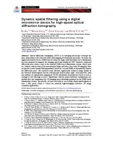
Fig. 1. Experimental setup: BE, beam expander; NF, neutraldensity filter; M, mirror; O, object wave; R, reference wave. Inset, detail of the off-axis geometry.
2. Hologram Acquisition and Reconstruction
The geometry discussed here corresponds to the case of Fresnel off-axis holography proposed in digital holography by Schnars and Ju¨ptner.21 In recent publications we presented a new reconstruction method for phase-contrast imaging7 and a configuration for holographic microscopy.22 Only amplitude-contrast imaging is discussed here; however, it is clear that the undesired terms can be eliminated in the same way in the phase-contrast images and that the method presented here can be applied generally to process digital off-axis holograms. A detailed description of the digital holography method is given in Refs. 7 and 22. A diagram of the experimental setup is illustrated in Fig. 1. Linearly polarized plane wave fronts are produced by a beam expander BE including a pinhole for spatial filtering. A 15-mW He–Ne laser is used as the light source. A CCD camera records the hologram that results from the interference between the object wave O and the reference wave R. Two neutral-density filters are used to adjust the object and the reference intensities. To obtain off-axis holograms, the orientation of the mirror 共M兲 that reflects the reference wave is set such that the reference wave reaches the CCD with an incidence angle while the object wave propagates perpendicular to the hologram plane 0xy 共see inset in Fig. 1兲. Particular attention must be paid to the adjustment of , which must not exceed a maximum value max for which the carrier frequency of the interferogram is equal to the Nyquist frequency of the detector,
冉 冊
ⱕ max ⫽ arc sin
, 2⌬x
(1)
where is the wavelength and ⌬x is the pixel size. We obtain the reconstructed wave front ⌿共m, n兲 in the observation plane 0 by computing the discrete
册冎
i 2 2 共k ⌬x ⫹ l2⌬y2兲 d
,
(2)
m,n
where k, l, m, n are integers; FFT is the fast-Fouriertransform operator; d is the distance between the hologram and the observation plane; and A ⫽ exp共i2d兾兲兾共id兲 is a constant. ⌬x and ⌬y define the sampling intervals in the hologram plane. The sampling intervals in the observation plane 共⌬ and ⌬兲 are related to the size of the CCD 共L兲 and to the distance d by the following relation: ⌬ ⫽ ⌬ ⫽ d兾L.
(3)
The reconstructed wave front is an array of complex numbers. An amplitude-contrast image and a phase-contrast image can be obtained by calculation of the intensity 关Re共⌿兲2 ⫹ Im共⌿兲2兴 and the argument 兵atan关Re共⌿兲兾Im共⌿兲兴其 of ⌿共m, n兲, respectively. In Eq. 共2兲 RD共k, l 兲 is a computed replica of the reference wave called the digital reference wave. As explained in Ref. 7, this digital reference wave is introduced for phase-contrast imaging but is not necessary for amplitude-contrast imaging. 3. Spatial Filtering of Off-Axis Holograms A.
Introduction
In the hologram plane 0xy the interference between the object wave O and the plane reference wave R produces a distribution of intensity, which is generally written as an addition of four terms, IH共x, y兲 ⫽ Ir ⫹ Io共x, y兲 ⫹ R*O ⫹ RO*,
(4)
where Ir is the intensity of the reference wave and Io共x, y兲 is the intensity of the object wave. R*O and RO* represent the interference terms with R* and O* denoting the complex conjugates of the two waves. Lets assume that, as with classical holography, the hologram reconstruction is achieved by illumination with a plane wave U. The reconstructed wave front in the hologram plane is then given by ⌿共 x, y兲 ⫽ UIr ⫹ UIo共x, y兲 ⫹ UR*O ⫹ URO*.
(5)
The first term on the right-hand side of Eq. 共5兲 is the product of Ir by the illumination wave U. Since R is a plane wave, Ir is uniform, and this term represents a plane wave propagating along the direction of U. The second term, sometimes called the ambiguity term, is the product of U by the object intensity. Since Io共x, y兲 is generally nonuniform, it produces a wave that propagates along the direction of U within a cone, the angular aperture of which depends on the 10 August 2000 兾 Vol. 39, No. 23 兾 APPLIED OPTICS
4071
spatial spectrum of the object wave. Together, the first two terms on the right-hand side of Eq. 共5兲 form the zero order of diffraction. The third and the fourth terms in Eq. 共5兲 are produced by the interference terms, and each of them generates an image of the specimen. UR*O produces a virtual image located at the position initially occupied by the object. If the reconstruction is performed by illumination of the hologram with a replica of the reference wave 共U ⫽ R兲, the virtual image is produced by a replica of the object wave multiplied by the reference intensity 共IrO兲. The fourth term URO* produces a real image located on the other side of the hologram. If U ⫽ R*, the real image is produced by a replica of the conjugate of the object wave multiplied by the reference intensity 共IrO*兲. In classical holography the condition U ⫽ R or U ⫽ R* is required only for so-called thick holograms for which the recording of the interference in the thickness of the photographic emulsion defines a Bragg condition for the illumination wave.23 In digital holography this condition is required only for phase-contrast imaging. With in-line geometries the hologram is recorded with an object wave and a reference wave with parallel directions, and the four components of the reconstructed wave front ⌿ propagate along the same direction and cannot be observed separately. The idea with off-axis holography is that if O and R arrive in the hologram plane with separated directions, the different terms will vary at different spatial frequencies and, as a consequence, will propagate along separated directions during the reconstruction. For example, if we assume a reference wave of the form R共x, y兲 ⫽ 公IR exp兵ik sin x其, the hologram intensity becomes IH共x, y兲 ⫽ Ir ⫹ Io共x, y兲 ⫹ 冑I R exp共⫺ik sin x兲O ⫹ 冑I R exp共ik sin x兲O*.
(6)
The phase factor exp共⫺ik sin x兲 in the third term indicates that the wave producing the virtual image is deflected with an angle ⫺ with respect to the direction of the illumination wave U. The same phase factor appears in the fourth term but with the opposite sign, meaning that the wave producing the real image is deflected with an angle . If we now consider the Fourier transform of the hologram intensity, the influence of the two phase factors exp共⫾ik sin x兲 can be interpreted as a translation of the spatial frequencies associated with the real and the virtual images. If we assume that U is in normal incidence, the spatial frequencies of the zero order of diffraction are located in the center of the Fourier plane, and the spatial frequencies of the interference terms vary at different carrier frequencies, which are located symmetrically with respect to the center of the Fourier plane: ⫺k sin 兾2 for the virtual image and k sin 兾2 for the real image. This suggests that the different terms of the reconstructed wave front can be spatially filtered. This task could be achieved optically during a conventional optical reconstruction with two lenses in a 4f configuration with an appropriate 4072
APPLIED OPTICS 兾 Vol. 39, No. 23 兾 10 August 2000
mask inserted in the Fourier plane of the first lens. We show in Subsection 3.B that in our case this procedure can be performed digitally by multiplication of the computed Fourier transform of the hologram with a numerically defined mask. From the point of view of signal processing it is interesting to realize that the off-axis geometry introduces a spatial modulation of the interference terms. By analogy with the lock-in detection, which uses a temporal modulation, the method of spatial filtering that is presented here can be considered to be equivalent to the application of a bandpass filter, which results in an enhancement of the signal-to-noise ratio 共or signal-to-background兲 ratio. A method of in-line digital holography involving a temporal modulation of the interference terms with the application of a bandpass filter to the temporal signal acquired by each pixel of the CCD was reported in Ref. 16. B.
Results and Discussion
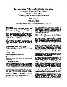
Figure 2共a兲 presents a hologram recorded with the experimental setup presented in Fig. 1 with a U.S. Air Force resolution test target as object. The image in Fig. 2共a兲 contains 512 ⫻ 512 pixels, and its area 共area of the sensitive chip of the CCD兲 is L2 ⫽ 4.85 mm ⫻ 4.85 mm. Interference fringes that are characteristic of the off-axis geometry are observable in this image. The computed two-dimensional Fourier spectrum of the hologram is shown in Fig. 2共b兲 where we can see that the different terms of the interference produce well-separated contributions. Spatial frequencies corresponding to the zero order of diffraction are located in the center of Fig. 2共b兲. Except for the contribution of the reference intensity Ir, which produces a Dirac delta function at the origin frequency, the spectrum of zero order of diffraction represents the spectrum of the object wave intensity Io共x, y兲. The spatial frequencies of the interference terms R*O and RO* are located symmetrically with respect to the center of the image. Their distances to the center depend on the incidence angle , which must be large enough to ensure a complete separation of the zero-order spatial frequencies from those of the interference terms. The two letters P in Fig. 2共b兲 indicate the contributions produced by parasitic reflections occurring at interfaces in the experimental setup. Although the effects of these parasitic reflections cannot be detected in the hologram itself because of their low intensity, their contributions are clearly observable in the hologram spectrum, because they arrive on the CCD with incidence angles that are distinct from the incidence angle of the object wave. Figure 2共c兲 presents the amplitude-contrast image obtained by numerical reconstruction of the hologram presented in Fig. 2共a兲. The image contains a real image, a virtual image, and a zero order of diffraction. This image was obtained for a reconstruction distance d ⫽ 31.0 cm 关see Eq. 共2兲兴. To obtain a focused real image, this distance must be approximately equal to the optical path length separating the object and the CCD during the hologram recording. The same hologram can also be
Fig. 2. Elimination of the zero order of diffraction by spatial filtering. 共a兲 Original off-axis hologram, 共b兲 two-dimensional Fourier spectrum of the original hologram, 共c兲 amplitude-contrast image obtained by numerical reconstruction of the original hologram, 共d兲 filtered hologram, 共e兲 two-dimensional Fourier spectrum of the filtered hologram, 共f 兲 amplitude-contrast image obtained by numerical reconstruction of the filtered hologram. The filtered hologram in Fig. 2共d兲 is obtained by computation of the inverse Fourier transform of the filtered spectrum presented in Fig. 2共e兲.
reconstructed with the virtual image in-focus when we take a negative reconstruction distance 共d ⫽ ⫺31 cm兲. Figures 2共c兲 and 2共f 兲 do not present the entire area of the reconstructed images but only a region of interest that contains the zero order of diffraction and the two conjugate images. The
complete reconstructed images are square and contain 512 ⫻ 512 pixels. The size of objects appearing in the reconstructed images can be determined with Eq. 共3兲, which gives the pixel size in the observation plane. Figure 2共e兲 presents the filtered spectrum obtained 10 August 2000 兾 Vol. 39, No. 23 兾 APPLIED OPTICS
4073
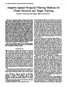
by multiplication of the Fourier transform of the original hologram with a mask that eliminates all spatial frequencies except those of the interference terms. The computation of the inverse Fourier transform of the filtered spectrum results in a filtered hologram presented in Fig. 2共d兲 where we can see that the fringe visibility is enhanced in comparison with Fig. 2共a兲. In Fig. 2共f 兲, which presents the corresponding numerically reconstructed image, we can see that the zero order of diffraction has been eliminated. As low spatial frequencies of the hologram are filtered the dc component of the interference is suppressed. As already mentioned in Ref. 17, this means that the intensity of the filtered hologram contains negative values. Of course, this feature could not be envisaged in classical optical holography. The mask used for spatial filtering consists of two transparent windows centered around the carrier frequencies of the interference terms R*O and RO*. To avoid suppression of the high-frequency components of the interference terms, the area of these transparent windows must be chosen as large as possible. Since the two-dimensional function describing the transmission of the mask is defined numerically, a great flexibility is offered for its definition. A combination of transparent and opaque windows of various shapes and sizes can be used to filter the undesired spatial frequencies while keeping intact the contributions of the interference terms. Windows with smoothed transmission profiles such as Gaussian, Hamming, or Tukey windows can be used to avoid the occurence of high-frequency fluctuations in the reconstructed images, which may arise if parts of the spectrum of the real or of the virtual image are truncated. If we compare Figs. 2共c兲 and 2共f 兲, we can see that the major effect of the applied image processing method is high-pass filtering, which results in the elimination of the zero order of diffraction. As a consequence, the contrast of the image is improved, because the whole intensity range is distributed in the area of the real image in Fig. 2共f 兲, whereas a large part of it is covered by the zero order of diffraction in Fig. 2共c兲. A contrast enhancement of 20% was measured in this example. Another effect is the suppression of the noise produced by the parasitic reflections indicated by the two P’s in Fig. 2共b兲. As shown in Fig. 3, the twin image can also be eliminated with an asymmetrical mask composed of only one transparent window centered around the carrier frequency of one of the interference terms. In Fig. 3共a兲 the real image has been selected, and the filtered spectrum contains only the contribution of RO*, shifted from the center by the carrier frequency. This frequency shift can be eliminated by translation of the selected spatial frequencies to the center of the spectrum before the calculation of the inverse Fourier transform. Since a large area of the spectrum presented in Fig. 3共a兲 is free of spectral information, it is possible to reduce the image size, and as a consequence the processing time, by means of extracting a region of interest 共typically 256 ⫻ 256 pixels兲 from the 4074
APPLIED OPTICS 兾 Vol. 39, No. 23 兾 10 August 2000
Fig. 3. Virtual image elimination. 共a兲 Filtered two-dimensional Fourier spectrum, 共b兲 numerically reconstructed amplitudecontrast image.
Fourier transform of the hologram. In this case the method proposed here resembles the so-called Fourier-transform method, which is sometimes used for interferogram analysis.24,25 Since the hologram is a real function, its Fourier transform is symmetric with its complex conjugate, Hermitian symmetry 关F共⫺兲 ⫽ F*共兲兴, meaning that the real part of the Fourier transform is an even function 兵Re关F共⫺兲兴 ⫽ Re关F共兲兴其 and that the imagi-
nary part is an odd function 兵Im关F共⫺兲兴 ⫽ ⫺Im关F共兲兴其. If the mask used for spatial filtering is also symmetric 共as presented in Fig. 2兲, these symmetries are preserved, and the inverse Fourier transform can be represented by a real function 共a hologram兲. In contrast, if the mask is not symmetric 共as presented in Fig. 3兲, these symmetries are lost, and the inverse Fourier transform must be represented by a complex function defined in amplitude and phase. Therefore the twin-image elimination requires that the inverse Fourier transform be computed with an algorithm that returns a complex function. In this case the inverse Fourier transform of the filtered hologram spectrum does not provide a hologram in the strict sense but gives the amplitude and the phase of the selected interference terms 共R*O or RO*兲 in the hologram plane. The same algorithm 关Eq. 共2兲兴 can still be applied for the reconstruction, but the digitized hologram intensity IH共k, l 兲 must be replaced with the obtained complex field. If the retained spatial frequencies are not shifted to the center of the spectrum, the complex field obtained after computation of the inverse Fourier transform is multiplied by a phase factor of the type exp关⫺2i共 fx x ⫹ fy y兲兴, where fx and fy represent the two components of the carrier frequency of the interference term. 4. Conclusion
A digital method has been developed for eliminating the zero order of diffraction and the twin image in off-axis digital holography. The method consists of filtering the spatial frequencies associated with these undesired terms in the computed Fourier transform of the hologram. It has been established that the application of the method results in an improvement of the quality of the reconstructed images, in particular a contrast enhancement and a reduction of the noise produced by parasitic reflections. An important point is that, when spatial filtering is performed with an asymmetrical mask for twin image elimination, the filtered hologram must be represented by a complex function, because of the property of Hermitian symmetry of the Fourier transform.
6.
7.
8.
9.
10.
11.
12. 13. 14.
15.
16.
17. 18.
19.
This study was supported by Swiss National Fund for Scientific Research grant 20-49628.96. The authors thank P. Dahlgren for her contribution.
20.
References
21.
1. U. Schnars, “Direct phase determination in hologram interferometry with use of digitally recorded holograms,” J. Opt. Soc. Am. A 11, 2011–2015 共1994兲. 2. O. Coquoz, R. Conde, F. Taleblou, and C. Depeursinge, “Performances of endoscopic holography with a multicore optical fiber,” Appl. Opt. 34, 7186 –7193 共1995兲. 3. J. Pomarico, U. Schnars, H.-J. Hartmann, and W. Ju¨ptner, “Digital recording and numerical reconstruction of holograms: a new method for displaying light in flight,” Appl. Opt. 34, 8095– 8099 共1995兲. 4. K. Boyer, J. C. Solem, J. W. Longworth, A. B. Borisov, and C. K. Rhodes, “Biomedical three-dimensional holographic microimaging at visible, ultraviolet and x-ray wavelength,” Nature Med. 2, 939 –941 共1996兲. 5. E. Leith, C. Chen, H. Chen, Y. Chen, D. Dilworth, J. Lopez, J.
22.
23. 24.
25.
Rudd, P.-C. Sun, J. Valdmanis, and G. Vossler, “Imaging through scattering media with holography,” J. Opt. Soc. Am. A 9, 1148 –1153 共1992兲. E. Cuche, P. Poscio, and C. Depeursinge, “Optical tomography at the microscopic scale by means of a numerical low coherence holographic technique,” in Optical and Imaging Techniques for Biomonitoring II, H. J. Foth, R. Marchesini, and H. Pobielska eds., Proc. SPIE 2927, 61– 66 共1996兲. E. Cuche, F. Bevilacqua, and C. Depeursinge, “Digital holography for quantitative phase-contrast imaging,” Opt. Lett. 24, 291–293 共1999兲. C. Wagner, S. Seebacher, W. Osten, and W. Ju¨ptner, “Digital recording and numerical reconstruction of lensless Fourier holograms in optical metrology,” Appl. Opt. 38, 4812– 4820 共1999兲. Y. Takaki and H. Ohzu, “Fast numerical reconstruction technique for high-resolution hybrid holographic microscopy,” Appl. Opt. 38, 2204 –2211 共1999兲. D. Beghin, E. Cuche, P. Dahlgren, C. Depeursinge, G. Delacre´taz, and R. P. Salathe´, “Single acquisition polarisation imaging with digital holography,” Electron. Lett. 35, 2053–2055 共1999兲. D. Gabor, “A new microscopic principle,” Nature 共London兲 161, 777–778 共1948兲; Proc. R. Soc. London Ser. A 197, 454 – 487 共1949兲. E. Leith and J. Upatnieks, “Microscopy by wavefront reconstruction,” J. Opt. Soc. Am. 55, 569 –570 共1965兲. L. Onural and P. D. Scott, “Digital decoding of in-line holograms,” Opt. Eng. 26, 1124 –1132 共1987兲. T.-C. Poon, K. B. Doh, B. W. Shilling, M. H. Wu, K. Shinoda, and Y. Suzuki, “Three-dimensional microscopy by optical scanning holography,” Opt. Eng. 34, 1338 –1344 共1995兲. T. Zhang and I. Yamaguchi, “Three-dimensional microscopy with phase-shifting digital holography,” Opt. Lett. 23, 1221– 1223 共1998兲. G. Indenbetouw and P. Klysubun, “Space-time digital holography: a three-dimensional microscopic imaging scheme with an arbitrary degree of spatial coherence,” Appl. Phys. Lett. 75, 2017–2019 共1999兲. T. M. Kreis and W. P. P. Ju¨ptner, “Suppression of the dc term in digital holography,” Opt. Eng. 36, 2357–2360 共1997兲. Y. Takaki, H. Kawai, and H. Ohzu, “Hybrid holographic microscopy free of conjugate and zero-order images,” Appl. Opt. 38, 4990 – 4996 共1999兲. See, e.g., E. N. Leith and J. Upatnieks, “Reconstructed wavefronts and communication theory,” J. Opt. Soc. Am. 52, 1123– 1130 共1962兲. E. Leith, P. Naulleau, and D. Dilworth, “Ensemble-averaged imaging through turbid media,” Opt. Lett. 21, 1691–1693 共1996兲. U. Schnars and W. Ju¨ptner, “Direct recording of holograms by a CCD target and numerical reconstruction,” Appl. Opt. 33, 179 –181 共1994兲. E. Cuche, P. Marquet, and C. Depeursinge, “Simultaneous amplitude-contrast and quantitative phase-contrast microscopy by numerical reconstruction of Fresnel off-axis holograms,” Appl. Opt. 38, 6994 –7001 共1999兲. J. W. Goodman, Introduction to Fourier Optics 共McGraw-Hill, San Francisco, Calif., 1968兲, Chap. 8. M. Takeda, I. Hideki, and S. Kobayashi, “Fourier-transform method of fringe-pattern analysis for computer-based topography and interferometry,” J. Opt. Soc. Am. 72, 156 –160 共1982兲. D. Malacara and S. L. DeVore, “Interferogram evaluation and wavefront Fitting,” in Optical Shop Testing, 2nd ed., Wiley Series in Pure and Applied Optics, D. Malacara ed. 共Wiley, New York, 1992兲, Chap. 13.
10 August 2000 兾 Vol. 39, No. 23 兾 APPLIED OPTICS
4075