Some MAC protocols using di- rectional antennas have been proposed in the past, which trade off spatial reuse and collision avoidance via a combination of ...
Spatial Reuse and Collision Avoidance in Ad Hoc Networks with Directional Antennas Yu Wang
J.J. Garcia-Luna-Aceves
Department of Computer Engineering University of California at Santa Cruz Santa Cruz, CA 95064 U.S.A. {ywang,jj}@cse.ucsc.edu
Abstract—The quest for efficient medium access control (MAC) protocols for multi-hop ad hoc networks has aroused great interest in using directional antennas. Some MAC protocols using directional antennas have been proposed in the past, which trade off spatial reuse and collision avoidance via a combination of omnidirectional and directional transmission modes. In this paper, it is argued that the benefit of spatial reuse achieved by a MAC protocol that uses directional mode in all transmissions can outweigh the benefit of a conservative collision avoidance MAC protocol that sends some omni-directional control packets to silence potential interfering nodes. Detailed simulation experiments of the popular IEEE 802.11 MAC protocol and its variants that make use of directional transmission mode in sufficiently random networks are presented. It is concluded that, in contention-based MAC protocols for multi-hop networks infested with hidden terminals, the aggressive channel access scheme featured by all-directional transmissions indeed outperforms other conservative schemes in terms of enhanced throughput and reduced delay.
I. I NTRODUCTION To address the inherent “hidden terminal” problem [1] in multi-hop ad hoc networks that can degrade throughput dramatically, some coordination between a pair of sending and receiving nodes and other potential interfering nodes to avoid collisions is mandatory. Various collision avoidance MAC protocols [2, 3] have been proposed in the recent past, and most of them employ a four-way handshake between a pair of sending and receiving nodes. That is, the actual data packet transmission and its acknowledgment are preceded by short request-tosend (RTS) and clear-to-send (CTS) packets from the sending and receiving nodes respectively. The RTS and CTS control packets are used to silence those neighboring nodes that can overhear these packets. These protocols differ in the lengths of control packets, whether packet sensing or carrier sensing is used, and the choice of backoff schemes. Though not all protocols can ensure collision-free transmissions of data packets, generally they are shown to alleviate, if not eliminate, the hidden terminal problem and thus perform much better than the carrier sense multiple access (CSMA) protocols [1]. This work was supported in part by the Defense Advanced Research Projects Agency (DARPA) under Grant No. DAAD19-01-C-0026 and by the US Air Force/OSR under Grant No. F49620-00-1-0330.
However, these schemes usually force all those neighbors who overhear the transmissions between the sending and receiving nodes to defer access to the shared channel during the whole handshake. This is required because any transmission of these neighbors can inadvertently collide with the on-going handshake. Thus, these schemes reduce substantially the possibility of spatial reuse enabled by multi-hop networks and can limit the maximum achievable throughput. Smart antennas or adaptive antennas have been used in cellular networks to narrow transmitting or receiving to certain directions while filtering out unnecessary interferences from other directions and thus greater throughput can be achieved. As a result, some researchers [4,5] have considered using these antennas in the design of MAC protocols for ad hoc networks. All the proposed schemes use directional transmission mode in transmitting data and acknowledgment packets, and the major differences among them lie in how control packets (RTS and CTS) are sent and how transmitting and receiving with directional antennas are modeled. For example, Ko et al. [4] propose two schemes. In one scheme, nodes use directional transmission of RTS packet and omni-directional transmission of CTS packet for collision avoidance. In the other scheme, nodes use both directional and omni-directional transmission of RTS packets alternatively. The omni-directional mode is used when the location of the receiver is not well known or all of the transmitting antennas are unblocked. It is clear that in these two schemes the authors are weighing the tradeoff between the increased possibility of simultaneous transmissions by neighboring nodes (scheme one) and the reduced possibility of collision of control packets (scheme two). Nasipuri et al. [5] also propose a different model for MAC protocol enabled by directional antennas. In the authors’ model, each node is equipped with M antennas whose orientations can be maintained all the time, regardless of the nodes’ movement. It is also assumed that nodes have directional reception capability, i.e., nodes can activate the antenna pointing to the direction of the desired source while deactivating antennas in other directions. Thus, the receiving node is not influenced by simultaneous transmissions from other directions. This is different from the model assumed by Ko et al. [4], in
Form Approved OMB No. 0704-0188
Report Documentation Page
Public reporting burden for the collection of information is estimated to average 1 hour per response, including the time for reviewing instructions, searching existing data sources, gathering and maintaining the data needed, and completing and reviewing the collection of information. Send comments regarding this burden estimate or any other aspect of this collection of information, including suggestions for reducing this burden, to Washington Headquarters Services, Directorate for Information Operations and Reports, 1215 Jefferson Davis Highway, Suite 1204, Arlington VA 22202-4302. Respondents should be aware that notwithstanding any other provision of law, no person shall be subject to a penalty for failing to comply with a collection of information if it does not display a currently valid OMB control number.
1. REPORT DATE
3. DATES COVERED 2. REPORT TYPE
2002
00-00-2002 to 00-00-2002
4. TITLE AND SUBTITLE
5a. CONTRACT NUMBER
Spatial Reuse and Collision Avoidance in Ad Hoc Networks with Directional Antennas
5b. GRANT NUMBER 5c. PROGRAM ELEMENT NUMBER
6. AUTHOR(S)
5d. PROJECT NUMBER 5e. TASK NUMBER 5f. WORK UNIT NUMBER
7. PERFORMING ORGANIZATION NAME(S) AND ADDRESS(ES)
University of California at Santa Cruz,Department of Computer Engineering,Santa Cruz,CA,95064 9. SPONSORING/MONITORING AGENCY NAME(S) AND ADDRESS(ES)
8. PERFORMING ORGANIZATION REPORT NUMBER
10. SPONSOR/MONITOR’S ACRONYM(S) 11. SPONSOR/MONITOR’S REPORT NUMBER(S)
12. DISTRIBUTION/AVAILABILITY STATEMENT
Approved for public release; distribution unlimited 13. SUPPLEMENTARY NOTES 14. ABSTRACT 15. SUBJECT TERMS 16. SECURITY CLASSIFICATION OF:
17. LIMITATION OF ABSTRACT
a. REPORT
b. ABSTRACT
c. THIS PAGE
unclassified
unclassified
unclassified
18. NUMBER OF PAGES
19a. NAME OF RESPONSIBLE PERSON
5
Standard Form 298 (Rev. 8-98) Prescribed by ANSI Std Z39-18
which antennas are always active for receiving and thus transmissions to different antennas result in failed reception. In the proposed MAC protocol, omni-directional RTS and CTS packets are first exchanged between a pair of sending and receiving nodes and then antennas of these two nodes are directed towards each other to receive ensuing data and acknowledgment packets. It can be inferred that collision avoidance is weighed more in this scheme by using omni-directional mode in transmitting control packets, though it also has the advantage that the locations of the sending and receiving nodes need not be known by each other in advance. These schemes have been shown to perform better than the existing omni-directional IEEE 802.11 MAC protocol on top of which most ad hoc routing protocols are built. However, the performance evaluations are done in relatively simple, regular network topologies and do not provide much insight in the interaction between spatial reuse and collision avoidance, where the former opts for directional transmission while the later opts for omni-directional transmission. It is also not clear whether the combination of omni-directional and directional transmission modes featured by the proposed schemes indeed achieves the optimal tradeoff between spatial reuse and collision avoidance. Therefore, in this paper, we investigate the interaction between spatial reuse and collision avoidance when directional antennas are utilized. We first show that the use of omni-directional transmission mode for control packets can largely nullify the spatial reuse benefit of directional antennas in Section II. We then propose that a scheme in which all transmissions are directional may perform better than other conservative schemes that transmit some control packets in omni-directional mode for collision avoidance. In Section III, we elaborate on the antenna and network models to be used in our simulations. Then in Section IV, simulation results of three MAC schemes based on the popular IEEE 802.11 MAC protocol are presented. It is shown that the MAC scheme in which all transmissions are directional indeed achieves the best performance among the three in terms of enhanced throughput and reduced delay. Section V concludes this paper. II. S PATIAL R EUSE OR C OLLISION AVOIDANCE ? It is a popular belief that collision avoidance is of paramount importance in the design of MAC protocols for multi-hop ad hoc networks due to the adverse effects of hidden terminals. Collision avoidance schemes have been shown to alleviate, if not eliminate, the hidden terminal problem. These schemes require coordination from those overhearing neighboring nodes who then have to defer access to the shared channel during the whole handshake. However, there are potentially two problems associated with these schemes. One is that spatial reuse is greatly reduced. Not only are the direct neighbors (or one-hop neighbors) discouraged from initiating any transmissions, but also the two-
GROUP 1
GROUP 2
E
D B A
C
F
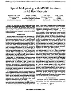
Fig. 1. Spatial Reuse vs Collision Avoidance
hop neighbors1 of the nodes partaking in a handshake are discouraged from initiating handshakes with one-hop neighbors of the nodes. The effect is especially prominent when an ad hoc network is composed of loosely coupled groups which are connected by a few “hub” nodes, as shown in Fig. 1. In Fig. 1, the dashed lines show where inter-group communications take place. It is clear that, when omni-directional RTS/CTS scheme is enforced, the inter-group communications can almost prevent other inner-group communications from taking place. Similarly, certain inner-group communications will also prohibit inter-group communications. Hence, the achievable throughput can be unduly low. The other problem is that, with the increase of one-hop and two-hop neighbors, it is more difficult to get all the nodes coordinated well due to the random nature of the channel access and the limited information available to each node. Not knowing other nodes’ contention status (busy, idle, deferring or backing off), nodes may have to choose artificially very large backoff values to shift the times of their attempts to access the channel and thus much of the valuable channel resource is wasted in waiting. The above discussion may lead to the conclusion that collision avoidance becomes ineffective in relatively crowded multi-hop networks. In fact, the conclusion is supported by prior work [6, 7]. Some researchers have realized the benefit of spatial reuse enabled by directional antennas and their proposed schemes have been introduced in Section I. In these schemes, omnidirectional transmission of some control packets (most notably, CTS packets) are unanimously used for collision avoidance. The effort to have a balanced tradeoff between spatial reuse and collision avoidance is conspicuous. However, here we will show that the omni-directional transmission of CTS packets can largely nullify the spatial reuse, even if other packets are transmitted directionally. Referring back to Fig. 1, consider the four nodes A–D. Suppose A and B have packets for each other and the same is the case for C and D. After an examination of this scenario, it is clear that only flows A → B and C → D can coexist at the same time, because the omni-directional CTS 1 Here we refer to those nodes that have at least one common neighbor with a node but are not direct neighbors of the node as the node’s two-hop neighbors.
from either A or C prevents the flow at the other side from taking place. Even under the assumption of the capability of directional reception [5], those nodes who overhear a CTS still have to defer access to the channel for the whole handshake according to the specification of the protocol. The directional reception capability just helps to filter out some interference from others nodes that cannot receive the CTS clearly and it does not improve spatial reuse much either. Thus, it is dubious if the omni-directional CTS scheme performs much better than the basic scheme in networks with sufficiently random topologies. However, in a scheme where all transmissions are directional, flows A → B or B → A can coexist with either C → D or D → C and spatial reuse is maximized. Even though the use of directional transmissions does not force all neighboring nodes to defer access to the shared channel, collisions will not necessarily happen if these neighboring nodes do not transmit in the direction of either the sender or the receiver. For example, in Fig. 1, nodes E and F do not defer access for B and the handshake between them will not affect B if the transmission beamwidth is sufficiently narrow. Obviously, the use of omnidirectional transmission of CTS packet can be quite disruptive in these cases. Based on the above arguments, we can reason that an alldirectional transmission scheme2 may achieve better throughput than those conservative collision-avoidance schemes when the benefit of spatial reuse outweighs that of collision avoidance, which we investigate hereafter. III. S IMULATION M ODELS Different assumptions can be made regarding the functionalities of directional antennas. We make the following assumptions in our model: • A node is equipped with antennas such that, when directional transmission with a beamwidth of θ is used, nodes outside the beamwidth will not receive any signal from the node. • When a node is transmitting with one of its antennas, it appears “blind” in other directions. This is also the case when each node is equipped with only one steerable antenna. When a node is transmitting, it cannot sense any other channel activity at all. • We do not assume directional reception capability, which is a node’s ability to receive transmissions from one direction only, while deactivating antennas pointing to other directions to avoid unnecessary interference. The rationale behind these assumptions is that the majority of mobile nodes to be deployed in ad hoc networks in the near future are unlikely to be equipped with multiple powerful directional antennas on a par with base stations in current cellular networks. 2 Despite
the name’s similarity to omni-directional, here it refers to the specific scheme where all packets are transmitted directionally just for the sake of simplicity.
In contrast with the rather regular network topologies used previously, where nodes are placed on a uniform grid, nodes are distributed uniformly in planar circles (or rings) in our network model. In this way, nodes are distributely much less regularly, because nodes can have different number of one-hop neighbors and two-hop neighbors in different directions. To be specific, we place nodes in concentric circles or rings. That is, given that a node’s transmitting and receiving range is R and that there are on average N nodes within this circular region, we place N nodes in a circle of radius R, subject to a uniform distribution. Because there are on average 22 N nodes within a circle of radius 2R, we place 22 N − N = 3N nodes outside the previous circle of radius R but inside the concentric circle of radius 2R, i.e., the ring with radii R and 2R, subject to the same uniform distribution. Then 32 N − 22 N = 5N nodes can be placed in an outer ring with radii 2R and 3R, and so on. To filter out boundary effects that some boundary nodes face less contention and may attain higher than average throughput, we just focus our attention on the average performance of the innermost N nodes. According to our experiments, conclusions drawn from a circular network of radius of more than 3R do not affect the conclusion to be drawn in the next section. Therefore, we present only the results for a circular network of radius 3R. To avoid some extreme cases, we only use network topologies that satisfy the following requirements: • For the inner N nodes, each node should have at least 2 neighbors and at most 2N − 2 neighbors. • For the intermediate outer 3N nodes, each node should have at least 1 neighbor and at most 2N − 1 neighbors. To be specific, even when nodes are distributed uniformly, the number of the neighbors of any node in such networks can still vary considerably. It is not uncommon for some innermost nodes to have no neighbors while some other nodes have more than 3N neighbors, if we do not enforce such requirements. In our simulation, we investigate three typical MAC schemes. In the first one, all packet transmissions are omnidirectional, which is just the scheme commonly used in traditional MAC protocols that emphasizes collision avoidance. For the sake of simplicity, we call this scheme “ORTS-OCTS.” Though there are quite a few “dialects” of this scheme, we choose the IEEE 802.11 MAC protocol as the example. In the second case, an RTS packet is transmitted directionally and CTS packet is transmitted omni-directionally and then data packet and acknowledgment packet are transmitted directionally. This is the scheme that tries to strike a balance between collision avoidance and spatial reuse, and it is called “DRTSOCTS” scheme. The third case is called “DRTS-DCTS,” in which all packet transmissions are directional. Obviously, this scheme emphasizes spatial reuse. IV. S IMULATION R ESULTS In this section, we investigate the performance of the three schemes introduced in Section III. We use GloMoSim 2.0 [8]
TABLE I IEEE 802.11
PROTOCOL CONFIGURATION PARAMETERS
RTS CTS data ACK DIFS SIFS 20-byte 14-byte 1460-byte 14-byte 50µsec 10µsec contention window slot time sync. time prop. delay 31–1023 20µsec 192µsec 1µsec
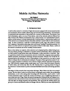
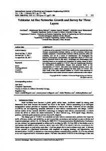
as the network simulator. The traditional IEEE 802.11 MAC protocol just uses ORTS-OCTS scheme. We implement the other two schemes based on the existing IEEE 802.11 implementation for fair comparison. Direct sequence spread spectrum (DSSS) parameters are used throughout the simulations, which are shown in Table I. The raw channel bit rate is 2Mbps. In our simulation, each node has a constant-bit-rate (CBR) traffic generator with data packet size of 1460-byte, and one of its neighbors is randomly chosen as the destination for each packet generated. All nodes are always backloged. We run simulations with N = 3, 5, 8 with beamwidth θ = 30◦ , 90◦ and 150◦ . We generate 50 random topologies that satisfy the uniform distribution and then obtain averaged throughput and delay for the N nodes in the innermost circle of radius R for each configuration. The results are shown in Figs. 2 and 3. In these figures, the vertical lines show the range of throughput achieved by each scheme, that is mean ± standard variance. These lines are shifted a bit for clarity. It can be seen that the throughput of the DRTS-DCTS scheme does not degrade much in a relative large range of transmission beamwidths when N is small and the throughput of the DRTSOCTS scheme degrades very little regardless of the transmission beamwidth. This can be explained as follows. When a node has few neighbors, it usually does not make much difference if the node transmits with either a narrower or a wider beamwidth. For example, if a node has three neighbors that are distributed around it, it can transmit with beamwidth of either 30◦ or 90◦ . However, in reality, it is usually more desirable to transmit with narrower beamwidth, because signal energy is more concentrated and a higher signal-to-noise ratio can be achieved, though physical layer impairment other than Gaussian white noise is not modeled in the simulations. Fig. 3 also shows that narrower beamwidth transmissions can lead to reduced delay in the DRTS-DCTS scheme. The results reported in Figs. 2 and 3 clearly show that the DRTS-DCTS scheme outperforms the other two MAC schemes when beamwidth is narrow. In addition, it is also shown that the DRTS-OCTS scheme performs only marginally better than the ORTS-OCTS scheme in the random topologies investigated here. This shows that the unwitting use of omnidirectional transmission of CTS packet can make almost all overhearing but non-interfering hidden terminals defer access to the channel, and thus can nullify almost all the spatial reuse benefit that directional transmissions bring forth. These results confirm the conjectures made in Section II. It is also clear from Fig. 3 that, with a more aggressive
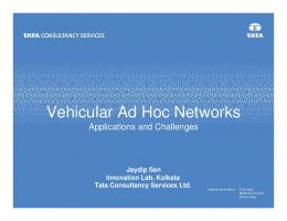
way of channel access to achieve spatial reuse, DRTS-DCTS scheme also enjoys on average less delay than the other two schemes, especially when N is large. In addition, it is also desirable to use narrower beamwidth in the DRTS-DCTS scheme, even when it does not affect the throughput much for the case of small N , because nodes are less affected by the surrounding sending and receiving nodes and thus can spend less time waiting. We also experiment with some configurations in which the number of nodes in the innermost circle of radius R is different from N and we denote it by i. By choosing different values of i, we can vary the contention densities around these nodes. When i is more than N , the transmissions to and fro these nodes loosely correspond to the inner-group communications shown in Fig. 1. When i is smaller than N , then the transmissions loosely correspond to the inter-group communications shown in Fig. 1. Due to space limitation, The results show we only show the results for the case when N = 5, i = 3, 5, 10 in Fig. 4 and more results are available from the authors upon request. It is clear that the DRTS-DCTS scheme still outperforms undisputably the other two schemes, even when the contention densities are not uniform. V. C ONCLUSION In this paper, we have discussed the tradeoff between spatial reuse and collision avoidance in contention-based MAC protocols for multi-hop ad hoc networks. It is shown that, when directional transmission is used, it is much better to use it throughout the whole handshake. The omni-directional transmission of some control packets for collision avoidance will in fact defeat the purpose of using directional antennas to achieve better throughput. Simulation results of some sufficiently random networks validate this argument and show that the DRTSDCTS scheme indeed outperforms the other two conservative collision-avoidance schemes in terms of both enhanced throughput and reduced delay. R EFERENCES [1] F. A. Tobagi and L. Kleinrock, “Packet Switching in Radio Channels: Part II - the Hidden Terminal Problem in Carrier Sense Multiple-access Modes and the Busy-tone Solution,” IEEE Trans. on Communications, vol. 23, no. 12, pp. 1417–1433, 1975. [2] J. J. Garcia-Luna-Aceves and C. L. Fullmer, “Floor Acquisition Multiple Access (FAMA) in Single-channel Wireless Networks,” ACM/Baltzer Mobile Networks and Applications, vol. 4, no. 3, pp. 157–174, 1999. [3] IEEE Computer Society LAN MAN Standards Committee, ed., IEEE Standard for Wireless LAN Medium Access Control (MAC) and Physical Layer (PHY) Specifications. IEEE Std 802.11-1997, The Institute of Electrical and Electronics Engineers, New York, 1997. [4] Y.-B. Ko, V. Shankarkumar, and N. H. Vaidya, “Medium Access Control Protocols Using Directional Antennas in Ad Hoc Networks,” in IEEE INFOCOM 2000, Mar. 2000. [5] A. Nasipuri, S. Ye, J. You, and R. E. Hiromoto, “A MAC Protocol for Mobile Ad Hoc Networks Using Directional Antennas,” in Proceedings of the IEEE Wireless Communications and Networking Conference (WCNC) 2000, (Chicago, IL, U.S.), Sept. 2000. [6] Y. Wang and J. J. Garcia-Luna-Aceves, “Collision Avoidance in MultiHop Ad Hoc Networks,” in Proc. of IEEE/ACM MASCOTS 2002, (Forth Worth, Texas, U.S.A.), Oct. 2002.
Throughput comparison (N=3)
Throughput comparison (N=5)
0.9
Throughput comparison (N=8)
0.8
0.7
DRTS−DCTS DRTS−OCTS ORTS−OCTS
0.8
DRTS−DCTS DRTS−OCTS ORTS−OCTS
DRTS−DCTS DRTS−OCTS ORTS−OCTS
0.7
0.6
0.7 0.6 0.5 0.6
0.5
0.4
Throughput
Throughput
Throughput
0.5
0.4
0.4
0.3
0.3 0.3 0.2 0.2 0.2
0
0.1
0.1
0.1
0
1/6
1/3
1/2 Beamwidth (x π radians)
2/3
5/6
0
1
0
1/6
1/3
(a) N=3
1/2 Beamwidth (x π radians)
2/3
5/6
0
1
0
1/6
1/3
(b) N=5
1/2 Beamwidth (x π radians)
2/3
5/6
1
(c) N=8
Fig. 2. Throughput Comparison – Set 1
Delay comparison (N=3)
Delay comparison (N=5)
80
Delay comparison (N=8)
120
DRTS−DCTS DRTS−OCTS ORTS−OCTS
180 DRTS−DCTS DRTS−OCTS ORTS−OCTS
70
DRTS−DCTS DRTS−OCTS ORTS−OCTS
160
100 140
60 80
120
40
Delay (ms)
Delay (ms)
Delay (ms)
50
60
100
80
30 40
60
20 40 20
10
0
20
0
1/6
1/3
1/2 Beamwidth (x π radians)
2/3
5/6
0
1
0
1/6
1/3
(a) N=3
1/2 Beamwidth (x π radians)
2/3
5/6
0
1
0
1/6
1/3
(b) N=5
1/2 Beamwidth (x π radians)
2/3
5/6
1
(c) N=8
Fig. 3. Delay Comparison – Set 1
Throughput comparison (N=5,i=5)
Throughput comparison (N=5, i=3)
Throughput comparison (N=5, i=10)
0.8
0.8
0.45
DRTS−DCTS DRTS−OCTS ORTS−OCTS
DRTS−DCTS DRTS−OCTS ORTS−OCTS 0.7
0.7
0.6
0.6
0.5
0.5
DRTS−DCTS DRTS−OCTS ORTS−OCTS
0.4
0.35
0.4
Throughput
Throughput
Throughput
0.3
0.4
0.25
0.2
0.3
0.3
0.15
0.2
0.2
0.1
0.1
0.1
0
0
1/6
1/3
1/2 Beamwidth (x π radians)
(a) N=5, i=3
2/3
5/6
1
0
0.05
0
1/6
1/3
1/2 Beamwidth (x π radians)
2/3
5/6
1
(b) N=5, i=5
0
0
1/6
1/3
1/2 Beamwidth (x π radians)
2/3
5/6
1
(c) N=5, i=10
Fig. 4. Throughput Comparison – Set 2
[7] Y. Wang and J. J. Garcia-Luna-Aceves, “Performance of Collision Avoidance Protocols in Single-Channel Ad Hoc Networks,” in Proc. of IEEE ICNP 2002, (Paris, France), Nov. 2002. [8] X. Zeng, R. Bagrodia, and M. Gerla, “GloMoSim: a Library for Parallel
Simulation of Large-scale Wireless Networks,” in Proc. of the 12th Workshop on Parallel and Distributed Simulations, May 1998.