Spatial-Temporal Characterization of Synchrophasor Measurement Systems. â A Big Data Approach for Smart Grid System Situational Awareness. 1.
Spatial-Temporal Characterization of Synchrophasor Measurement Systems — A Big Data Approach for Smart Grid System Situational Awareness 1
1
Huaiguang Jiang, Student Member, IEEE, 2 Lei Huang Student Member, IEEE, 1 Jun Jason Zhang, Senior Member, IEEE, 3 Yingchen Zhang, Member, IEEE, 1 David Wenzhong Gao, Senior Member, IEEE
Department of Electrical and Computer Engineering, University of Denver, Denver, CO 80210 2 Electric Power Research Institute, China Southern Power Grid, Guangzhou, 510080, China 3 National Renewable Energy Laboratory, Golden, CO 80401
Abstract—An approach for fully characterizing a synchrophasor measurement system is proposed in this paper, which aims to provide substantial data volume reduction while keep comprehensive information from synchrophasor measurements in time and spatial domains. Specifically, the optimal synchrophasor sensor placement (OSSP) problem with the effect of zero-injection buses (ZIB) is modeled and solved to ensure the minimum number of installed sensors and also the full observability of the power system. After the sensors are optimally placed, the matching pursuit decomposition algorithm is used to extract the time-frequency features for full description of the time-domain synchrophasor measurements. To demonstrate the effectiveness of the proposed characterization approach, power system situational awareness is investigated on Hidden Markov Model (HMM) based fault detection and identification using the spatial-temporal characteristics generated from the proposed approach. Several IEEE standard systems such as the IEEE 14 bus system, IEEE 30 bus system and IEEE 39 bus system are employed to validate and evaluate the proposed approach. Index Terms—Smart grid, phasor measurement unit, fault disturbance recorder, optimal sensor placement, matching pursuit decomposition, hidden Markov model, situational awareness
I. I NTRODUCTION With the evolution of energy and power systems, the emerging Smart Grid (SG), featured by distributed renewable energy generations and demand-response control, is facing a new challenge in extremely large data sets, namely the Big Data challenge [1]. The data sources of a future electrical power system, or Smart Grid, are heterogenous, including smart metering devices at the consumer side, automated revenue metering at the electricity market side, synchrophasor measurement data for situational awareness, power system component state and operation control data, as well as large data sets from sources other than power system measurements, such as geographic information system data. In this paper, we aim to provide our initial considerations, investigation, and a possible solution to the Big Data challenge in characterization of the synchrophasor measurement system (SMS). Recently, synchrophasor measurement devices, such as phasor measurement units (PMUs) and fault disturbance recorders (FDRs), have been used as measurement device for smart grid (SG) monitoring. Widely distributed synchrophasor sensors in SG can record the multi-modal signals for power system situational awareness, including power system fault detection and identification, which is critical for shorting response time and improve system reliability to avoid cascading outages [2]. In real-world applications, the number of synchrophasor sensors in SG should be limited and the placement of the
���������������������������������,(((
sensors should be optimized, which is due to the following reasons: i.) a three-phase PMU is typically installed in an electrical substation, and the installation and operational costs are very high; ii.) the FDRs, which are low-cost single-phase phasor measurement units, can result in a huge data volume, as they can be installed at ordinary 120 V outlets with a low cost and collect phasor measurements at a high data rate up to 1.44 kHz. Early work on the optimal PMU placement (OOP) problem was investigated based on generalized integer linear programming (ILP) formulation [3]. Contingency conditions of line outage or PMU loss are considered with OPP in [4]. In this paper, aiming to provide the full network observability, an optimal synchrophasor sensor placement (OSSP) approach is investigated to determine the minimal number and optimal location of synchrophasor sensors. The results of OSSP provide the spatial characterization of the synchrophasor measurements, and in time domain we propose to use the matching pursuit decomposition (MPD) with Gaussian atom dictionary for fully characterizing the signals. The MPD provides an effective harmonic analysis approach to decompose the synchrophsor measurements with high fidelity with high data compression capacity. Also, the extracted feature vector by MPD can be used directly for power system situational awareness [5]. The usage and effectiveness of the spatial-temporal synchrophasor characterization is demonstrated using power system situational awareness. In the last few decades, research of machine learning such as the support vector machine (SVM) and artificial neural network (ANN) indicates that there is a promising way to detect and diagnose power system faults [6]– [8]. Using the generated spatial-temporal characteristics, various hidden Markov models (HMMs) are trained for detection and identification power system faults to achieve situational awareness. The paper is organized as following. In Section II, the OSSP problem formulations in different scenarios are described. In Section III, the MPD algorithm is presented for synchrophasor signal feature extraction. In Section IV, HMMs based fault detection and identification are presented for different fault scenarios. In Section V, numerical results of the proposed spatial-temporal characterization as well as the fault analysis approach are presented. II. O PTIMAL S YNCHROPHASOR S ENSOR P LACEMENT The objectives of OSSP are to minimize the number of synchrophasor sensors, while to maximize the measurement
���
$VLORPDU�����
redundancy for ensuring full system observability. In this section, the concept of topological observability is adopted and the following rules are applied [9] for OSSP. • If the voltage phasor and current phasor at one end of a branch are known, the voltage phasor at other end of that branch can be obtained using Ohm’s law. • If the voltage phasors at both ends of a branch are known, the current phasor through this branch can be calculated. The measurements such as bus voltage phasors and branch current phasors, directly obtained from the synchrophasor sensors, are referred to as direct measurements. Measurements derived by employing the above two rules are referred to as indirect measurements, or pseudo measurements. In an observable network, each and every bus must be observed at least once by using direct or indirect measurement. The OSSP placement at a bus can be seen as a binary decision variable defined as � 1 if synchrophasor sensor is placed at bus i (1) ui = 0 otherwise For a system with n buses, the optimal sensor placement problem can be formulated as an integer linear programming problem as follows, min F =
n �
c i ui
i=1
�n subject to constraints: fi = ≥ 1, i = j=1 ai,j uj 1, 2, 3, ..., n, where ci is the cost of installing a synchrophasor sensor at bus i. The cost of synchrophasor sensor installation at each bus is assumed to be equal to 1 per unit in the present study. fi refers to the number of times that the ith bus is observed through synchrophasor measurements. ai,j is the (i, j)th entry of system connectivity matrix defined as � 1 if i = j or if i and j are connected ai,j = (2) 0 otherwise 1) OSSP considering the effect of zero-injection buses: If the effect of ZIBs is considered, the total number of synchrophasor sensors in OSSP problem will be futher reduced due to the following rules • In a zero injection cluster (ZIC), if the zero-injection bus is observable and its adjacent buses are all observable except one, then the unobservable bus will be identified as observable by applying Kirchhoff’s Current Law (KCL) at ZIB. • In a ZIC, if all the buses are observable except the zeroinjection one, then the zero-injection bus can be also identified as observable by using nodal equations. Combining these two cases can lead to the conclusion that a ZIC is observable when it has at most one unobservable bus. 2) OSSP considering single sensor outage: Outage of a sensor at bus h, can be considered into the previous OSSP by setting the corresponding decision variable uh to zero. To facilitate the formulation of the optimization problem, a parameter, pi,j is defined as follows: � 0 if h=j (3) pi,j = 1 otherwise
then, the associated constraints to OSSP problem considering single sensor outage are as fi =
n �
pi,j ai,j uj ≥ 1, ∀i, ∀h
(4)
j=1
3) OSSP considering single line outage: Outage of a line may cause loss of observability for one of its terminal buses, which would otherwise be observable using the current phasor of that line. For a power network with M lines, M single line contingencies can be defined. Thus the constraints of single line outage can be presented as: fi =
n �
ali,j uj ≥ 1, ∀i, ∀l,
(5)
j=1
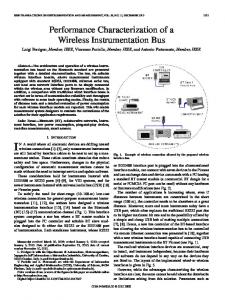
where the parameter ali,j = 0 if the lth line connects buses i and j, and ali,j = ai,j otherwise. In summary, combining the aforementioned constraints corresponding to different scenarios, the OSSP problem can be formulated and solved for full spatial characterization of synchrophasor measurements in a SG. The IEEE 14 bus system is used as a test bench for investigating our proposed OSSP problem. From the computed resulted of OSSP shown in Table I, without considering ZIB, only 4 sensors are required to observe the whole power system. If considering ZIB, only 3 sensors are required. However, if considering single line outage and single sensor outage, 9 and 10 sensors are needed, respectively. Considering both single line outage and single sensor outage, 11 sensors are needed. The effect of ZIB is considered in the simulations in the scenarios of single line outage, single sensor outage, and single sensor/line outage. 13 14 12 11
10 9
6 1
5
8
7 4
2
Fig. 1.
3
The IEEE 14 bus system.
III. T IME -F REQUENCY C HARACTERIZATION OF S YNCHROPHASOR M EASUREMENTS Matching pursuit decomposition proposed in [5] is an effective time-frequency analysis algorithm. In this section, MPD with Gaussian atom dictionary is used to analyze signals and extract the signal features represented by the amplitude, time-shift, frequency-shift and variance of the Gaussian atoms. It is expected that the MPD can generate an efficient characterization of the synchrophasor measurement system.
���
TABLE I C OMPARISON OF OSSP RESULTS IN IEEE 14 B US S YSTEM Scenario Type Number of Sensors Location of Sensors Ignoring the effect of ZIB 4 1-2, 4, 6, 8, 10-11, 13-14 Considering the effect of ZIB 3 2, 6, 9 Single Line Outage 9 1-2, 4, 6, 8, 10-11, 13-14 Single Sensor Outage 10 1-2, 4-6, 9-11, 13-14 Single Sensor/Line Outage 11 1-2, 4-6, 8-11, 13-14
����
The MPD algorithm is summarized as following [5]. Assuming a continuous signal s(t) can be decomposed as a weighted summation of the Gaussian atoms, we have ∞ �
αp gp (t) ,
���� 9ROWDJH�SX
s(t) =
(6)
αp gp (t) + rN (t) .
����
����
where αp is the coefficient for the Gaussian atom gp (t), gp (t) is selected from a given Gaussian atom dictionary, and p is the index. The convergence of this representation is defined in [5]. Furthermore, the completeness is required for the Gaussian atom dictionary D, although the orthogonality is not required. The original signal s(t) can be represented using decomposition with finite iterations and a remainder rN (t) with small energy residual as s(t) =
����
����
p=1
N −1 �
Installation Rate 28.6 21.4 64.3 71.4 78.6
�
�
�
�
��
��
��
��
��
��
(a) ���� ���� )UHTXHQF\�+]
���� ���� ���� ����� ����� ����� �����
(7)
�
�
�
p=1
�
� 7LPH�V
(b)
With the notations in (7), the MPD algorithm is described as follows. Let r1 (t) = s(t), and the atoms gp (t) is selected from the Gaussian atom dictionary D as the one that has the maximum magnitude of the projection in rp (t), where p = 1, 2, 3 · · · P . Specifically gp (t) is obtained using � � � ∞ � gp (t) = arg max rp (t) g (e) (t)dt� , (8) g (e) (t)∈D
� 7LPH�V
−∞
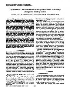
where e = {τ, ν, σ} are the time-shifting, frequency-shifting and related shape parameter for the Gaussian atoms. The MPD analysis can decompose a signal with a controllable residual signal power, and usually after a small number of decomposition iterations, the extracted signal features can be used to synthesize the original signal with very high fidelity. As a result, it is expected that this approach can fully characterize the synchrophasor measurements. One example of the MPD on the voltage phasor signal corresponding to a transmission line ground fault in the IEEE 14 bus system is illustrated in Fig. 2. The simulation duration of this scenario is 15 s with a transmission line grounding fault occurring between bus 2 and bus 5 (30% close to bus 2) for 6 cycles. The voltage signal is collected from bus 2. The MPD uses 1,800,000 Gaussian atoms and 30 iterations. As shown in Fig. 2(a), the red curve is the original voltage signal and the blue curve is the synthesis voltage signal using the composition of selected Gaussian atoms. The synthesized signal tracks the original signal very well. It is observed that the red and blue curves are almost identical. As Fig. 2(b) illustrates, the voltage signal can be decomposed into several Gaussian atoms, which are used to present the feature of the original signal.
Fig. 2. (a) The voltage oscillation curve and synthesis curve using MPD, (b) the time-frequency analysis of 2(a).
IV. H IDDEN M ARKOV M ODELS F OR FAULT D ETECTION AND I DENTIFICATION Using the spatial characterization obtained by OSSP in Section II and temporal characterization by MPD in Section III, the power system situational awareness can be analyzed and achieved. In this section, power system fault detection and identification are investigated to validated and evaluated the proposed characterization approached. Different HMMs are trained to detect and identify faults in SG for power system situational awareness. As the algorithm flowchart in Fig. 3 illustrates, two HMMs, Λ0 and Λφ are trained and used to detect faults and distinguish between the normal condition and abnormal conditions of the SG. Also for the mth fault type, an HMM Λ(m) is trained to identify the fault type m after the fault occurs. 7\SH�� 7\SH�� 6WDUW
+00� )DXOW� 'HWHFWLRQ