Aug 18, 2005 - that support building energy simulation. Software interfaces have been developed in both ... efficiency in the designs they submit to their clients.
Ninth International IBPSA Conference Montréal, Canada August 15-18, 2005
SPECIFICATION OF AN IFC BASED INTELLIGENT GRAPHICAL USER INTERFACE TO SUPPORT BUILDING ENERGY SIMULATION Barry O’Sullivan1 and Marcus Keane1 1 IRUSE, Dept. of Civil and Environmental Engineering/Environmental Research Institute, National University of Ireland, Cork, Ireland
ABSTRACT Significant R&D work has been on going in the development of integrated software environments that support building energy simulation. Software interfaces have been developed in both academic and industrial settings that support an integrated approach to the development of building energy simulation models. However, software interfaces developed to date lack in the depth with regard to HVAC systems information and the ability to offer simplified generic models for a range of known building types, activities, HVAC systems etc. This paper describes an integrated software environment that supports the seamless integration of all aspects of a building required to develop and perform black box dynamic building energy simulation with a particular emphasis on the Heating Ventilation and Air Conditioning (HVAC) components and systems to support proposed EU Directive 2002/91/EC and its associated the asset rating process.
INTRODUCTION In 2003 the European Parliament implemented Directive 2002/91/EC [EU Legislation, 2002], which assigns penalties to building owners who do not quantify the energy usage of their buildings throughout its life cycle against performance benchmarks set down by the relevant government. This directive will be enforced in 2006 generating an increase in awareness in consultancies of the necessity to use the energy simulation software that is available to them to provide maximum energy efficiency in the designs they submit to their clients. The Building Life Cycle, which is being referred to in the directive, defines the entire life of a building from design, through conception, occupancy and on to eventual demolition. This creates a need for longterm energy efficient designs to be present in all buildings. The concept of a Building Information Model (BIM) describes an integrated data model that stores all of the information relevant to a building throughout the
building life cycle. The BIM is a central data model where all information can be accessed by a variety of tools dealing with the entire building definition. This will remove the need for a new building model to be developed for each tool. In order to fully realise the acceptance of BIM’s a universal standard had to be created. The International Alliance for Interoperability (IAI) was founded in 1995 from a group of organisations from the AEC industry with the vision of improving communication, cost and quality throughout the building life cycle through software interoperability [IAI 1995]. Industry Foundation Classes (IFC’s) were developed by the IAI to help them achieve this mission. IFC’s are the only non-proprietary, intelligent way of creating integrated data models of buildings and they are also the only data model that is an accepted ISO standard. The data model is still being developed but the latest version IFC2x2 was released in 2003.
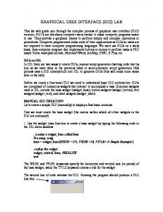
ENERGY MODELLING: A recent report derived from working to match the Kyoto Protocol showed that of all the CO2 emissions in Europe over 40% of such emissions derive from energy use in buildings. Research has indicated that CO2 emissions from buildings across the EU could be reduced by 22% through improved energy efficiency [EPBD Working Group, Ireland 2005]. This fact has prompted EU legislation and subsequently increased the attention of companies and their clients on the importance of building energy simulation. Figure 1 shows a project expenditure graph from a recent cost engineering journal [Kinney and Soubiran, 2004] that shows that the first weeks of concept design for a new building can account for up to 80% of the cost commitment in a project. Clients need to be presented with facts such as these in order to fully grasp the implications of early design decisions. The EU Directive 2002/91/EC provides the platform to push for client education as to the environmental and economic cost benefits. If the energy efficiency of a building can be reduced even more at this stage due to the use of building energy simulation then it can only be of
- 875 -
benefit to the client, the company, and ultimately the environment.
Figure 1 Project Expenditure Commitment Curve Vs Project Spending Curve [Source: Kinney and Soubiran, 2004]
COMMERCIAL PRACTICALITIES OF ENERGY SIMULATION: One of the main reasons for the lack of uptake by building designers is the perceived (and real) complexity associated with the building energy simulation tools, which many rightly assume to involve a steep learning curve before they can be properly utilised. This would involve a loss of manhours to the consultancies for something that at the moment is seen as more of an optional extra for the client than as a necessary step in the design process. While it can be true that some of these tools are currently inaccessible to inexperienced users the interfaces or these tools are improving and the future penalties resulting from not using energy simulation far outweighs the cost of man-hours needed to adapt to this design method. Another large problem with convincing consultancies to adapt to the use of these programs is their dependency on the traditional methods of prescriptive design. It can be quite difficult to convince a building designer to change to a new method of design that will cost them slightly more time if the benefit of this work is to another design team member, or, as in the case of many projects, a totally different company. It is the need to revolutionise the way major companies perceive the building life cycle design that will ultimately decide on whether or not BIM’s are successfully incorporated into building design. Client education will again be one of the main driving forces behind this change. As the monetary penalties, due to be prescribed by the Government agencies enforcing EU Directive 2002/91/EC, become more widely enforced the clients will want proof of the performance of their buildings to protect themselves against such liability. The companies which utilise energy simulation software the most successfully will be the ones attracting the greater number of clients as energy simulation models become a deliverable in
every project proposal. If larger consultancies start to incorporate these methods into their design process then the smaller companies will follow to remain competitive. If the larger companies can ensure interoperability between the software used by their various departments (architectural, HVAC, electrical, CFD, etc.) it will enable a seamless integration of the use of BIM’s throughout the building life cycle and thus lower costs and penalties that would have otherwise been incurred.
DATA-CENTRIC APPROACH TO BUILDING DESIGN: The current method of energy modelling is toolcentric, dealing only with short-term goals rather than long-term benefits. In a tool-centric approach each component of the modelling process has its own application, which uses its own data structure. Each time a new problem is encountered in the energy modelling process a mapping model must be created over which the application for solving this problem can now sit. This creates a multitude of models that often repeat the same definitions of the building to complete their solution. The tool-centric approach is represented on the left in Figure 2 whereas the data centric approach is on the left [Augenbroe, 2002].
Figure 2 Differences in Tool-Centric and DataCentric Approaches to Building Energy Simulation The data-centric approach however deals with a number of interfaces sitting on top of a single Building Information Model. This results in the avoidance of repetition in data input and subsequently an increased speed in data transfer between activities (Architectural, HVAC, structural, etc). This method has already been utilised in the Building Design Advisor program, which was developed as an interface manager to sit on top of a number of applications [Papamichael et al. 1997]. To support this BIM a series of non-proprietary advanced interfaces must be developed so that the total solution is more powerful than the sum of the individual parts. If the process is quicker using a tool-centric approach because of a weak link in the BIM interfaces then there is little reason for companies to change their design methods.
- 876 -
The major drawback of the tool-centric approach is that each interface is allied to an application that is only designed for one purpose. This means that certain generically necessary information, such as the geometric definition of the building, has to be remodelled in each application by another building designer who has the expertise in a different application. This can cause significant reduction in the speed of the design process in order to avoid the inherent errors of this transfer method.
nodes is often confusing unless a consistent naming method is strictly adhered to and this is one of the more common causes for errors in the production of a valid working model. This in turn slows down the design process making it a less desirable tool than it should otherwise be. EnergyPlus relies strictly on rules of branch topology and system loops to define the HVAC systems and the process of interpreting these rules by an inexperienced user can lead to a slower design process.
To support the integration of these interfaces into the design process context-sensitive design conditions must be created. Use cases must be developed to decide on the appearance of the interface so that the design engineer is dealing with their usual method of design.
DYNAMIC THERMAL SIMULATION
INTEGRATED DATA MODELS AND ENERGYPLUS EnergyPlus, which is an evolution of a combination of BLAST and DOE-2, is the first building Energy Simulation program that directly supports the IFC data model and has its own middleware program that can translate, from third-party CAD applications, the geometric information necessary for dynamic thermal simulation. EnergyPlus is constantly being developed with extra functionality and improved accessibility constantly being added [EnergyPlus 2005].
Dynamic Thermal Simulation involves everything from geometric zone description to occupancy schedules and from HVAC system design to the Uvalues of the building materials. While most of these other elements of the Dynamic Thermal Simulation process have also encountered problems similar to those of the HVAC system, their issues have been addressed with the introduction and continuing development of new software in these areas. The HVAC area of the dynamic thermal simulation is still found to be lacking in this respect. A number of existing problems with the current method of HVAC information input have repeatedly been put forward as technical specifications that may be addressed by the new interface. •
A number of interfaces and middleware products to EnergyPlus have been created and are currently being used to simplify the data input method. Some of these interfaces are already quite advanced, such as DesignBuilder [DesignBuilder,UK], EP-Quick and EplusInterface [EnergyPlus 2005], but they lack the functionality of an advanced HVAC system design process.
Time required for input: There is a lack of accessible interfaces for some areas of the BIM resulting in a time-consuming simulation design process.
•
The IFC HVAC Interface [Bazjanac and Maile 2004] middleware product takes IFC defined HVAC information and converts it to an IDF file for simulation purposes in EnergyPlus. It can alternatively be used to convert an IDF-defined HVAC system for storage in the IFC based BIM.
Unnecessary repetition of certain input fields: This particularly applies to the definition of nodes. Some very important nodes require input in up to seven different input fields. In large buildings, input strings can be very similar and mismatches nodes are highlighted in the error files all too often
•
Loop information input: While using IDF Editor, a large amount of time has to be spent searching through objects and fields to ascertain the relevant input information. Important input fields can often be missed because they are stored in objects whose relevance is not seen by the inexperienced user.
•
Scanning through a system design: Before running a simulation it can be difficult to visualise the layout of the HVAC system to ascertain the accuracy of the design. It can also be time-consuming when opening an existing simulation file that needs to be recalibrated to find the appropriate component or branch without having a clear picture of the HVAC schematic.
Figure 3 Data Conversion from IFC to IDF Unfortunately this still leaves the unanswered problem of creating the HVAC system in either format in the first instance. The current method of manual text input is both unnecessarily laborious but also extremely prone to error for inexperienced users of the simulation program. The correct connection of
- 877 -
•
•
•
System Viewer program: The existing HVAC system viewer after a simulation run (svg file) is not particularly user friendly, as it does not allow the user to pan around the system. This is especially frustrating for the user when dealing with large ventilation systems supplying air to multiple zones.
deliverable in client presentations, they have agreed to assist us to with advice on their desired real world application of this interface throughout its development.
Interoperability Issues: Certain IFC compatible programs such as ArchiCAD represent zones using a Global Unique ID such as “5KfeG2DVX1PEUntGwXlj3b” as well as the user-specified zone name, which can be very confusing and difficult to replicate during manual input.
•
Context sensitive to current design methods, so that the switch to this interface is as seamless as possible;
•
Intuitive HVAC design models repetitive information input;
•
Facilitate the automatic generation of user-driven reports.
Report Generation: Selecting the required information for the report generation after a simulation run is done at the end of the IDF Editor interface which can be time consuming in larger systems when trying to remember which nodes in which zones the user wanted to monitor the output for.
PROPOSED SOLUTION – HVAC GUI: Figure 4 demonstrates the proposed interaction of a new stand-alone HVAC GUI with both EnergyPlus and the BIM. The initial development of this interface will be dependent on middleware products as shown to produce its IFC compatibility but once it is functioning fully the IFC compliancy will be added.
Figure 4 Integration of HVAC GUI with BIM and E+ The content of this new HVAC interface has been developed in discussion with building design engineers, from both Project Management [PM, 2005] and Arup Consulting Engineers [Arup, 2005] in Cork, Ireland, who are actively using building energy simulation to analyse their designs. After discussing their interest in moving towards interoperable software for quicker energy simulation given the impending increase in the importance of having building energy performance as a quantifiable
The initial steps in developing these use cases have resulted in the formulation of the following user specifications for the interface:
to
avoid
Table 1 indicates how the interface proposes to deal with the user problems and technical specifications. The interface shall initially have the ability to read and also to output in the EnergyPlus specific IDF format, which will facilitate the simulation and, if necessary afterward, the calibration of the system using EnergyPlus. The fully calibrated file can then be run through the IFC HVAC Interface middleware program so that it can be integrated into the existing BIM (which will be an IFC-based open data model). The interface shall eventually have the added functionality of dealing directly with IFC files coming from the BIM. While this interface is largely pandering to the tool-centric approach, the IFC compliancy will transform it into a non-proprietary application, which will subsequently support the data-centric approach of building energy simulation modelling. The reason behind this initial tool-centric approach is a result of inheriting the legacy software of EnergyPlus, which is now helping to define the rule base that underwrites the entire interface. USER PROBLEMS/ TECHNICAL SPECIFICATIONS Slow input process for HVAC information Unnecessary repetition of node information Difficulty in visualising the system as created by text Time consuming method of report generation is error prone in larger systems
SOLUTIONS PROPOSED New graphical interface to speed up input Automatic generation of node information On-screen development of a HVAC system schematic Simple on-screen method of specifying required reports
Table 1 Some of the Technical Specifications Addressed by the New Interface The information necessary from the BIM pre-process includes the geometric definitions of the zones and the construction material definitions. Once the final HVAC system design has been simulated by EnergyPlus the IDF file is then run back through IFC
- 878 -
HVAC Interface, which will only convert it to a HVAC representation of the complete IDF file before adding the original IFC2x2 geometric representation to it. The use of ASHRAE and CIBSE guidelines to select ISO standard symbols will also assist in making this interface more context sensitive to the user as the systems that are designed on screen can be printed as provisional design schematics for the user when completed. One of the benefits over the previous HVAC system viewer (svg file viewer) will be the pan and zoom controls with which the user can easily traverse the full system design.
EnergyPlus. Four of these fields are automatically generated based on the schematic on the screen. Two more have the option of autosize as a default value and the operating schedule of the coil can be selected from a list of operating schedules that have been predefined by the user. This leaves the name of the coil as the only field that requires the user to input.
CONTENT OF GUI: Many of the technical specifications, which have been described earlier in the paper, were determined through use of the energy simulation software and detailed analysis of the internal object relationships. However it is equally important to address the user specifications as detailed in the previous section. Some of the concepts behind delivering on these specifications are described below.
Figure 5 Provisional Screenshot of Interface Drag and drop interface allowing design engineers to devise the HVAC layout in their traditional schematic design process. These building designers can create their HVAC schematic on-screen as they normally would have done on paper. The underlying framework of the interface decides on the validity of input by the user by checking for unconnected nodes, checking that the values are within the allowable valid parameters and also shall automate default values for certain unfilled fields.
Figure 6 Closer Inspection of Interface Screenshot The values are then stored to the database until the whole design has been completed at which stage it shall be written to an IDF file and the user will have the option of launching EnergyPlus. More specifically, each element of the on-screen schematic will have its own set of rules as defined by both the EnergyPlus IDD (Input Data Dictionary) file and the ASHRAE and CIBSE Guides on system design. Again the heating coil definition is provided as an example in Figure 7 below. These rules will govern which fields are accessible to the user during design of a system and which ones are only being shown on the screen so that the user can be assured that they are, for example, connecting the hot water loop to the inlet node of a heating coil rather than to the outlet node of the coil. The step of automatically extracting node information from the schematic will reduce much of the repetitive nature of the current manual text input method and also help to cut down on the margin of error in the initial simulation test.
The current design of the interface addresses all of the specifications defined by the consultants as illustrated. Figure 5 represents the overall design screen for a typical three-zone air loop. Each component of this loop can be selected, as is shown here with the heating coil, and a minimum of information is now needed to complete the definition of the component. In this heating coil example there are eight fields as defined by the IDD file for
- 879 -
Figure 7 Coil Definition in IDD file
The development of an understanding of the necessary rule base has come after detailed study of the EnergyPlus Input Data Dictionary, which defines exactly what input is necessary for each object, which fields have maximum and minimum values and, when they are allowed, what the default values should be. A large number of seemingly unrelated objects are defined within EnergyPlus with only the IDD file as a clear indication of the relation to each other as shown. These relationships, which must be followed by the user to avoid input error in the simulation, are demonstrated in Figure 8. The underlying structure of this interface takes into account all of these relationships in order to reduce the necessary user input to an absolute minimum. Some of the node information shall remain visible to the user but at a read-only level so that they may check on the interconnectivity in depth at a glance if they so wish. One user specification that has already been suggested is to simplify the process of assigning nodes for the report generation. The same problem is being encountered with deciding on report generation as has occurred with assigning values to other objects within EnergyPlus. The process of selecting the report specifications is often coupled within the menial task of checking back through pages of an IDF file to ensure the correct node is being selected. A much simpler method would be that once the
schematic has been completed the user could select a report generation tool and then click on the desired component on the schematic selecting the information they desire to be reported from that component after the simulation. Figure 9 estimates the impact this interface will have on both input accuracy and on cutting down input time. This graph is considering a large multi-storey building with multiple zones on each floor. The Average Time Taken in the different simulation design stages includes time spent debugging the associated errors discovered by EnergyPlus during simulation. Also, the times shown in the graph above are conservative estimates for experienced EnergyPlus users, whereas the time taken for an inexperienced user with the current input method could amount to weeks of effort before some of the errors become apparent.
Figure 9 Comparisons of Input Methods
Figure 8 Diagram showing direct relationships between Heating Coil and other IDD Objects
- 880 -
For instance in a large building the manual input of a full HVAC system will often cause errors through something as basic as a misspelled node name somewhere in the text file. Not only would the building design engineer have to type in hundreds of nodes in various areas of the IDF file but checking and rechecking these nodes is a painstaking but currently very necessary part of the process in order to prevent hours of debugging. The new HVAC interface will remove this entire process from the building design engineer and ensure that there is no node-associated debugging necessary.
COLLABORATIONS The interest shown in this project so far has allowed us to set up collaborations with DesignBuilder in the UK, and also with the Environmental Energy Technologies Division and the EnergyPlus design team in LBNL, California [LBNL 2005]. The intention is that we can investigate the options of tying this interface to the ones they have already developed.
CONCLUSIONS The development of this freeware interface will increase the attraction to the IFC-based open data model by making the energy simulation in EnergyPlus a quicker and more user-friendly process. The speed with which a building design engineer can now simulate their HVAC system will mean it can become an integral part of the design process for all buildings with a much reduced effect on the time cost of the design process. It is proposed to have an early version of the GUI in action by the end of 2005. It will exist initially as a stand-alone tool for EnergyPlus but it is envisaged that it will be possible to expand the definitions to support all IFC based energy simulation tools.
Graphisoft ArchiCADTM, 2003. http://www.graphisoft.com/products/archicad Augenbroe G., Trends in building simulation. Building and Environment 37 (2002) 891-902. EnergyPlus, A New-Generation Building Energy Simulation Program. 2001. http://www.eere.energy.gov/buildings/energyplu s Bazjanac V., 2004. Building energy performance simulation as part of interoperable software environments. Building and Environment 39 (2004) 879-883. Papamichael K., LaPorta J., Chauvet H. (1997) Building Design Advisor: automated integration of multiple simulation tools, Automation in Construction 6 (1997) 341-352 Bazjanac V. and Maile T. (2004) IFC HVAC Interface to EnergyPlus – A Case of Expanded Interoperability for Energy Simulation, SimBuild 2004, IBPSA-USA National Conference Boulder, Colorado, USA. DesignBuilder website, UK http://www.energycoding.com Lawrence Berkeley National Laboratory, University of California, Berkeley, California, USA. http://gundog.lbl.gov
REFERENCES International Alliance for Interoperability (IAI) http://www.iai-international.org DIRECTIVE 2002/91/EC OF THE EUROPEAN PARLIAMENT AND OF THE COUNCIL of 16 December 2002 on the energy performance of buildings http://www.energiecites.org/documents/opinions/directive_batiment s_en.pdf EPBD Working Group, Ireland. Draft Action Plan for Implementation of the EPBD in Ireland – Consultation Document. www.epbd.ie
Kinney C.L and Soubiran N (2004) Interactive Roadmap to Conceptual Cost Estimating, Cost Engineering Vol.46/No. 9, September 2004, AACE International, Morgantown, USA. Project Management Consulting Engineers (PM), Mahon, Cork, Ireland. http://www.pmg.ie Arup Consulting Engineers, Oliver Plunkett Street, Cork, Ireland. http://www.arup.ie
- 881 -
- 882 -