Aug 30, 2002 - Business Weekly (May 2, 1988): âLo- ... scale field program; 2) a mathematical modeling study; or 3) a ... Chapter 43 of the ASHRAE HandbookâHVAC Applications .... cally based on small-scale accidental releases, either liquid spills .... and Human Services, Public Health Service, Centers for Disease ...
The following article was published in ASHRAE Journal, August 2002. © Copyright 2002 American Society of Heating, Refrigerating and AirConditioning Engineers, Inc. It is presented for educational purposes only. This article may not be copied and/or distributed electronically or in paper form without permission of ASHRAE.
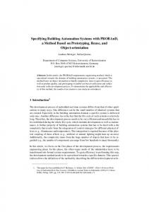
Figure 1a (left): Plume impact on taller downwind building. Figure 1b (right): Plume impact on taller upwind building.
Specifying Exhaust and Intake Systems By Ronald L. Petersen, Ph.D., Member ASHRAE, Brad C. Cochran, Member ASHRAE, and John J. Carter, Member ASHRAE
he design of exhaust stacks and air intakes needs careful consideration. Public concern has increased regarding air pollution in general. In addition, adverse exposure to air pollutants in the workplace can affect employee health and productivity. In some cases, releases of toxic pollutants may lead to litigation. The following newspaper article excerpts illustrate some of these issues.
T
Business Weekly (May 2, 1988): “Local residents were frightened. New pharmacology laboratories at the University of California at San Francisco were investigating everything from AIDS to parasitic diseases. Could disease organisms or toxic chemicals from those labs escape and harm citizens?” San Francisco Chronicle (September 5, 1996): “A barrage of letters and concerns about toxic chemicals have forced a circuit board manufacturer to drop, at least temporarily, plans to move next door to a peninsula high school.” Chicago Daily Herald (April 17,
30
1998): “Suspicions confirmed. Public health off icials say brain tumors at Amoco center more than coincidence.... A study of Building 503 at the Amoco Research Center in Naperville indicates a rash of malignant brain cancers…. Eighteen Amoco Research Center employees have developed brain tumors in the last 28 years.” Some challenges to specifying a good stack design include the existing building environment, aesthetics, building design issues, chemical use, source types, local meteorology and topography. For example, if a new laboratory building that
is being designed is shorter than surrounding buildings, it is difficult to design a stack so the exhaust will not impact neighboring buildings. The effect of a taller downwind or upwind building is illustrated in Figure 1. The figure shows how the plume hits the face of the taller building when it is downwind and how, when it is upwind, the wake cavity region of the taller building traps the exhaust from the shorter building. In either case, the plume impacts the face of the taller building. Figure 2 further illustrates problems that can be created by poor stack design. Fumes from the exhaust may reenter the building, enter adjacent buildings, or About the Authors Ronald L. Petersen, Ph.D., is vice president of Cermak Peterka Petersen Inc., Fort Collins, Colo. Brad C. Cochran is a senior project engineer for Cermak Peterka Petersen Inc. John J. Carter is a project engineer for Cermak Peterka Petersen Inc.
August 2002|ASHRAE Journal
Stack Design
impact pedestrians at unacceptable concentration levels. To avoid adverse air quality, taller stacks, higher volume flows and/or optimum locations on the roof may be necessary. In most cases, laboratory stack design is a balance between various constraints and obtaining adequate air quality at surrounding sensitive locations (air intakes, plazas, operable windows, etc.). The lowest possible stack height is desired for aesthetics, while exit momentum (exit velocity and volume flow rate) is limited by capital and energy costs, noise, and vibration. To determine the optimal exhaust design, predictions of expected concentrations of exhausted pollutants at sensitive locations are needed to compare against health limits and odor thresholds. These predictions can be accomplished with varying degrees of accuracy using three different methods: 1) a fullscale field program; 2) a mathematical modeling study; or 3) a reduced-scale study conducted within an atmospheric-boundary-layer wind tunnel. A full-scale field program may provide the most accurate prediction of concentration levels but can be expensive and time consuming. In addition, it is impossible to evaluate designs before construction is completed. Numerical models can be divided into two categories, analytical models and computational fluid dynamics (CFD) models. Analytical models assume a simplif ied building configuration and provide concentration estimates based on assumed concentration distributions, i.e., Gaussian. These models do not consider site-specific geometries that may substantially alter plume behavior. CFD models attempt to resolve the plume transport by solving the Navier-Stokes equations at finite grid locations. Windtunnel modeling, on the other hand, is much like conducting a field experiment where the concentrations are measured in a simulated flow at the points of interest over a scale model of the buildings under evaluation. This article describes a quantitative approach to accurately evaluate exhaust and intake designs to ensure acceptable air quality inside and around buildings. Also described for background purposes are various exhaust and intake design issues such as applicable standards and recommendations, analytical methods, plume rise, architectural screens, and entrained air exhaust stacks.
Figure 2: Illustration of potential air quality problems due to laboratory emissions.
4. Locate the air intake at the base of a relatively tall stack or tight cluster of stacks, if this location is not adversely affected by exhaust from nearby buildings. Intakes should not be located near the base of highly toxic stacks due to potential fan leakage.2 5. Avoid locating intakes near vehicle loading zones. Canopies over loading docks do not prevent hot vehicle exhaust from rising up to intakes above the canopy.2 6. Use High Efficiency Particulate Air (HEPA) filters or Ultra Violet Germicidal Irradiation (UVGI) systems of similar efficiency in isolation room exhaust streams.3 7. Combine several exhaust streams internally to dilute intermittent bursts of contamination from a single source, as well as producing an exhaust with greater plume rise. Additional air volume may also be added to the exhaust at the fan to achieve the same end.2 8. Group separate stacks together (where separate exhaust systems are mandated) in a tight cluster to take advantage of the increased plume rise from the resulting combined jet.2 Note that all the exhausts must operate continuously to take full advantage of the combined jet. 9. Avoid rain caps or other devices that limit plume rise on exhaust stacks. Conical rain caps often do not exclude rain, because rain does not fall straight down. Alternate design options are provided in Chapter 43 of the ASHRAE Handbook— HVAC Applications.2 10. Consider the adverse effect of architectural screens. A solid screen effectively decreases the stack height by 80%.4
Exhaust/Intake Design Issues
Analytical Methods
Applicable Standards and Recommendations
Chapter 43 of the ASHRAE Handbook—HVAC Applications discusses exhaust stack design in some detail.2 The chapter contains two primary types of information regarding stack design: 1) a geometric method of determining stack height; and 2) mathematical equations for predicting rooftop concentrations. In the geometric method, the recommended stack height is that for which the bottom edge of the exhaust plume will be above various recirculating and high turbulence zones. In general, this method is entirely inadequate for exhaust streams that contain toxic or odorous material, as it does not provide an estimated concentration at an air intake or other sensitive
Several organizations have published standards or recommendations regarding laboratory exhaust stack design as summarized here. 1. Maintain a minimum stack height of 10 ft (3 m) to protect rooftop workers.1 2. Locate intakes away from sources of outdoor contamination such as mobile traffic, kitchen exhaust, streets, cooling towers, emergency generators and plumbing vents.2 3. Do not locate air intakes within the same architectural screen enclosure as contaminated exhaust outlets.2
ASHRAE Journal|August 2002
31
Figure 3: Minimum recommended stack height above rooftop air intake using ASHRAE methods.
location. Hence, no information on the adequacy of the stack to avoid concentrations in excess of health or odor limits is provided. The analytical equations tend to be conservative for an isolated building or one that is significantly taller than the surrounding buildings and for air intakes on the roof level. Also, they are not appropriate for complex building shapes or when buildings of similar or taller height are nearby. Using the ASHRAE dispersion equations and a 400 µg/m3 per g/s ASHRAE design criterion, a graph can be generated giving the minimum recommended stack height to ensure that the design criterion is met, as shown in Figure 3.2,5 For example, assume an air intake is located 60 ft (18.3 m) away from an exhaust stack. The figure shows that a 20 ft (6.1 m) stack is needed if the volume flow rate is 1,000 cfm (0.47 m3/s), and a 10 ft stack (3 m) is needed with a 25,000 cfm (11.8 m3/s) volume flow rate. The figure clearly shows the benefit of higher volume flow rates. Plume Rise and Dispersion
Adequate plume rise is important to ensure that the exhaust escapes the high turbulence and recirculation zones on the building roof. Plume rise increases with increased exit momentum and decreases with increased wind speed.6 Reducing the diameter to increase exit velocity will enhance plume rise. However, a high exit velocity in itself does not guarantee adequate plume rise since the volume flow rate, and thus momentum, are factors as well. Plume rise is also degraded by increased atmospheric turbulence since the vertical momentum of the exhaust jet is more quickly diluted. If the ratio of exit velocity to approach wind speed is too low, the plume can be pulled downwards into the wake of the stack structure creating negative plume rise, a condition referred to as stack-tip-downwash. This downwash defeats some of the effect of a taller stack and can lead to high concentrations at the building surface. A rule of thumb for avoiding stack-tip-downwash is to have the exit velocity be at least 1.5 times the wind speed at the top of the stack.2 The wind speed exceeded 1% of the time is commonly used for estimating the minimum exit velocity required to avoid stack-tip-downwash.
32
Figure 4: Plume centerline height for conventional and entrained air exhaust systems.
ASHRAE provides a listing of 1% wind speeds for various metropolitan areas around the world.7 For a given stack design and receptor location, there is a “critical wind speed” causing the maximum concentration. Wind speeds lower than this critical speed result in greater plume rise; higher wind speeds provide more dilution due to the greater volume of air passing the exhaust stack. The critical wind speed increases with exit velocity, exhaust volume flow rate and stack height. Architectural Screens
Architects or building owners often want to hide their exhaust stacks using screening material. An ASHRAE funded research study was conducted to evaluate the effect of architectural screens on rooftop concentration levels.4 The study found that screens can significantly increase concentrations on the roof and, in effect, reduce the effective stack height. The study evaluated various enclosure sizes and heights but found that the main parameter affecting rooftop dispersion was the screen porosity. The results of the study provide a quantitative relationship between screen porosity and stack height. Entrained Air Exhausts
Entrained air exhaust manufacturers often quote an effective stack height for their system, which many designers consider when choosing the appropriate system. The effective stack height specification is based on a mathematical equation that predicts the height of the centerline of the emitted exhaust stream versus downwind distance.6 The effective stack height that is often presented is, in reality, the maximum height of the exhaust plume centerline at some large distance (say, 100 to 200 ft [30 to 61 m]) downwind of the stack and is not an effective stack height. What the manufacturers should supply as a specification is the “effective stack height improvement” over a conventional exhaust system. The stated improvement may not be as great as might be
August 2002|ASHRAE Journal
Stack Design
expected, as shown in the following analysis. Figure 4 shows the predicted plume centerline height (called effective stack height by some entrained air system suppliers) versus distance from the stack for a conventional exhaust system with a 15,000 cfm (7.1 m3/s) volume flow rate and a 3,000 fpm (15.2 m/s) exhaust velocity, and a typical entrained air system with a 25,000 cfm (11.8 m3/s) total volume flow rate and a 4,000 fpm (20.3 m/s) exit velocity. Plume centerline heights were calculated for 10 mph (4.5 m/s) and 20 mph (8.9 m/s) stack height wind speeds. The figure shows that the increase in plume centerline height (effective stack height improvement) for the entrained air system versus the conventional exhaust system is only 1 to 2 ft (0.3 m to 0.61 m) near the stack; and increases to 7 to 10 ft (2.1 to 3 m) at 100 ft (30.4 m) downwind. This analysis shows why the effective stack height specification is misleading. The manufacturers should be encouraged to delete this specification and add the specification of the “effective stack height improvement” over a conventional system. Recommended Analysis Approach The Basic Approach
The recommended approach to evaluating the air quality aspects of exhaust stacks is to perform dispersion modeling to demonstrate that expected concentrations do not exceed health limits or odor thresholds. The design recommendations and standards discussed earlier can be helpful in the design process, but they do not guarantee adequate air quality. The air quality acceptability question can be written: Cmax < Chealth ? (1) and Cmax < Codor ? (2) where Cmax is the maximum concentration expected at a sensitive location (air intakes, operable windows, pedestrian areas), Chealth is the health limit concentration and Codor is the odor threshold concentration of any emitted chemical. When a large number of potential chemicals are emitted from a building, a variety of mass emission rates, health limits and odor thresholds are examined. It then becomes operationally simpler to recast the acceptability question by normalizing (dividing) Equations 1 and 2 by the mass emission rate, m:
C C


![[PDF] Download The Scientific Design of Exhaust and Intake Systems ...](https://m.moam.info/img/260x300/pdf-download-the-scientific-design-of-exhaust-and-_6478a4b3097c4796708d0943.jpg)
![([PDF]) Scientific Design of Exhaust and Intake Systems - Google Sites](https://m.moam.info/img/260x300/pdf-scientific-design-of-exhaust-and-intake-system_64789eaa097c47a9708d087e.jpg)


![[PDF BOOK] Scientific Design of Exhaust and Intake ... - Google Sites](https://m.moam.info/img/260x300/pdf-book-scientific-design-of-exhaust-and-intake-g_6477f31b097c47a9708c4863.jpg)