SPEECH ENHANCEMENT FROM INTERFERING SOUNDS USING CASA TECHNIQUES AND BLIND SOURCE SEPARATION Tomasz Rutkowski, Andrzej Cichocki
Allan Kardec Barros
Lab. for Advanced Brain Signal Processing Brain Science Institute RIKEN Wako-shi - Saitama - JAPAN email: {tomek, cia}@bsp.brain.riken.go.jp http://www.bsp.brain.riken.go.jp/ ABSTRACT In this paper we propose novel biologically plausible model for segregation of one dominant speaker from the other concurrent speakers and environmental noise in real cocktailparty scenario. The developed method integrates two powerful techniques: computational scene analysis (CASA) and blind source separation (BSS) technique with bandpass preprocessing. Since each of these techniques applied alone has same limitations and drawbacks, we combine both methods in order to obtain improved performance. The computers simulations results show good performance for real room recordings, especially for the case where mixing convolutive (reverberant) system cannot be inverted by any of these method itself. 1. INTRODUCTION A fundamental problem in auditory and speech processing is the separation of speech produced by desired speaker from the concurrent speakers and acoustic environmental noise. This problem has been a focus of study using two approaches. The first approach is based on computational auditory scene analysis (CASA) techniques. This techniques are based on modelling auditory function of the human hearing. Recently also the problem of speech segregation has also been investigated with some limitations from the perspective of blind source separation by performing blind multichannel deconvolution in time or frequency domain [1, 2, 3, 4, 5]. Both of the above approaches have limitations and mostly problem of separation of speaker from reverberant mixture of many concurrent speakers, so called real cocktail party problem is still not solved. We introduce new model that incorporate the two above powerful techniques to solve the problem more efficiently be separating signals (correlograms) in time-frequency domain rather in time or frequency domain. Our simulations results show very good results for real room recordings, where mixing convolutive system cannot be in-
Depto. de Engenharia Eletrica Universidade Federal do Maranhao Sao Luis - MA - BRAZIL email:
[email protected]
verted using only single of incorporated methods. In many listening situations, the acoustic waveform reaching our ears is composed of sounds energy mixture from multiple sources. The fundamental task of auditory perception is to resolve such acoustic mixtures, in order to understand each or mostly one main sound source. Bregman [6] describes this problem of auditory function as an auditory scene analysis (ASA). From his studies, ASA is regarded as a two-stage process. The first stage, known as segregation, decomposes the acoustic mixture reaching the ears into a collection of sensory elements. In the second stage, known as grouping or streaming, elements that seems to be produced by the same source are combined together into streams, that later can be interpreted in higher level of auditory system processing units in the brain. Many studies shown [7, 8, 9] that ASA like preprocessing can improve speech separation results and also it is very helpful for proper segregation of audio features. Most of these studies have been motivated by the need for a front-end processor for robust automatic speech recognition in noisy environments. In our previous work [7, 8], we tried to separate signals by applying bank of bandpass filters with center frequencies around fundamental frequency F 0 and its harmonics of desired speaker, but problem becomes very difficult to attack, when speakers in mixtures have voices with very close F 0. Currently, computational ASA remains an unsolved problem for real-time engineering applications such as automatic speech recognition. The current state of the art in computational ASA stands in sharp contrast to the fact that humans and higher animals can perceptually segregate sound sources with apparent ease. It seems likely, therefore, that computational systems which are more closely modeled on the neurobiological mechanisms of hearing may offer performance advantages over current approaches. The model of our new approach to solve cocktail party problem is presented on Fig.1. We combined our previous model [7, 8] with CASA acoustic waveform preprocessing with its implementation indtroduced by
728
s1
x~1
x11
Auditory Filter Bank
M
Correlogram Frames
M
x21
BSE1
y1
M Correlogram Inversion
s2 ~ x2
Auditory Filter Bank
M
Correlogram Frames
x1N
Inversed Auditory Filter Bank
y = sˆ 1
yN
M x2N
BSEN
s3
Fig. 1. The conceptual model for speech segregation and enhancement . The blind signal extraction (BSE) is performed for correlograms in time-frequency domain rather in the time domain.
Slaney [10, 11]. The waveforms recorded using two microphones imitating human ears are split into subbands, which model cochlea style of acoustic stimuli accusation and the cochleagrams are created. In the next step depicted on Fig. 1 the correlograms are created from cochleagrams, to enhance periodical components of the speech. The outputs of correlograms are than processed using BSS units for every subband separately, so the separation units combine the function of separation and extraction (BSE). The only one output from every BSE unit is than reconstructed in the last part of our model, that performs auditory model inversion.
2.1. Cochleagram The Lyons auditory model puts particular attention on the behavior of the cochlea, which build the most important part of the human ear, and which is located in the inner ear. The way, cochlea preprocess auditory stimuli can be modelled as as a non-linear filter bank with overlapping subbands. In artificial implementations the behavior of cochlea can be simulated by a cascade filter bank. The bigger the number of these filters the more accurate is the model can be achieved but also the overall processing complicity increases. For our experiments we have considered a cascade of 66 filters for sampling rate of the signal 8kHz. For this purpose we employ cascade of ”gammatone” filters which have following impulse response: gi (t) = tn−1 exp(−2πbi t) cos(2πfi t + φi ) (1 ≤ i ≤ N ).
2. AUDITORY MODEL The auditory system of humans consists of various parts that interact converting the sound pressure waves entering the outer ear into neural stimulus. Understanding how these parts act has been the goal of many researches during the last years thus today it is possible to describe how signals are elaborated by the auditory system, but it is also possible to analyze signals using mathematical models that reproduce the auditory features. In this way we have the possibility to understand which kind of representations our higher levels in the brain use to isolate signals from noise, or to separate signals which have different pitches. If we want to reproduce the same operations, we have to be able to work on representations similar to those used by our brain. Beside that, we have also to be able to translate these representations in sound waves so that they can be objectively evaluated. As regards the auditory model, we have used Lyons passive cochlear model and its implementation presented by Slaney [10, 11, 12]. The model inversion was deigned with some slight modifications following the other work of Slaney et al. [13].
(1)
where N is the number of filter channels, n is the filter order and fi is the center frequency, φi is the phase and bi determines the rate of decay of impulse response. It was shown in many physiological studies of auditory nerve tuning curves that auditory filters are distributed in frequency according to their bandwidths, which increase quasilogographically with increasing center frequency. According to Glasberg and Moore [14] the filters are set to have equivalent rectangular bandwidth (ERB), a physiological measurement of critical bandwidth in human subjects ERB(f ) = 24.7(4.37f /1000 + 1).
(2)
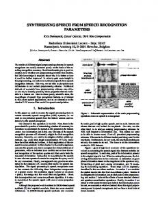
More precisely the decay rate for every subband can be defined [14] bi = 1.019ERB(fi ). (3) The exemplary frequency response for cascade filter bank is presented on Fig.2. To model the directional behavior of the inner ear cells (according to physiological results, that
729
20
channel #1
0
frequency bins
10 10
0
20 30 40 50
magnitude [dB]
−10
60 1250
−20
2500 time [ms]
3750
−30
1250
2500 time [ms]
3750
1250
2500 time [ms]
3750
frequency bins
channel #2
10
−40
0
−50
20 30 40 50 60
−60 2 10
3
10
1250
frequency [Hz]
Fig. 2. The frequency characteristics of band pass filters consisting 66 subbands emulating cochlea like signal acquisition. is how the hair cells in inner react for stimuli) the half wave rectifier (HWR) with soft saturation 12 (1+tanh(x+a)) was implemented [11]. The HWR drop the negative value of the waveform, cutting the energy of the signal by two. The next and important final step of cochlear preprocessing model consists of automatic gain control sections (AGC), that approximately represent the neural firing rates produced by the solicitation of various parts of cochlea caused by sound pressure waves entering the cochlea. The cochleagram is than a two dimensional map of subband processed signal in time with additional HWR and AGC postprocessing. The resolution of the cochleagram depends of the number of choosen subbands. In our case the filter bank divide the signal into 66 subbans, so we represent the signals in form of cochlear maps with dimensions 66 × signal length. The exemplary cochleagram of short sentence is presented on Fig.3.
2500 time [ms]
3750
Fig. 3. The cochleagrams for two channels of ”cocktail party problem” recordings. On the left side, there are two mixed waves from speech signals plotted in time domain and on the right side the cochleagrams for 66 channel auditory filter banks (the frequency bins numbering is descending for higher frequencies). where F and F −1 indicate the forward and inverse Fourier Transform and win(t) stands for smoothing filter window with assumption win(t) = 0 for t < 0 and t > T . The equation 4 can be rewritten: ZT c(t−s)win(s)c(t−s−τ )win(s+τ )ds. (5)
Rcc (τ, t) = 0
Finally it is also known, that correlogram is a function of position or frequency for every basilar membrane of the inner ear. So the most general form of the correlogram is written now using notation from the Fig.1: ZT ci,j (t − s)ci,j (t − s − τ )win(s)ds.
xi,j (τ, t) =
2.2. Correlogram
(6)
0
The correlogram is a short time autocorrelation made on all the outputs of the cochleagram subbbans. From the autocorrelation of a signal it is possible to extract the spectral power of the same signal, in fact the Fourier transform of its autocorrelation is equal to the square of its Fourier transform magnitude, that is: where is the autocorrelation of x(t). In the same way the magnitude or the STFT can be calculated from its STA. Therefore, by simple operations, we can obtain the magnitude of the short time Fourier transforms of all the output sequences of the cochleagram. The windowed autocorrelogram can be written ZT qt (s)qt (s + τ )ds = F −1 kF (q)k2
Rcc (τ, t) = 0
where qt (s) = c(t − s)win(s)
(4)
Finally autocorrelation is normalized to eliminate any indication of the relative power in different frequency channels. Since the autocorrelation doubles the dynamic range required to represent varying signal levels, Slanley and Lyon [11] suggested the normalization by the square root of power, so that the zero lag is equal to one: x ˆi,j (τ, t) =
xi,j (τ, t) . xi,j (0, t)1/2
(7)
The above autocorrelation produces non-negative output since the input is also non-negative after section of HWR representing hair cell activity. The correlogram is than again a two dimensional map constructed by computing described above autocorrelation with fixed delay for every row of cochleagram. The autocorrelation is computed based also on
730
sliding window of cochleagram with overlapping to correctly represent nonstationary behavior of speech signal. The correlogram described above represents function of time, frequency, and autocorrelation lag. The example of obtaining the correlograms from two channels recording is presented on Fig. 4. After computing correlograms of the sig-
frequency bins
channel #1, frame #1
channel #1, frame #2 10
10
20
20
20
30
30
30
40
40
40
50
50
50
60
60
60
50 100 150 200 250
50 100 150 200 250
frequency bins
10
10
20
20
30
30
30
40
40
40
50
50
50
60 50 100 150 200 250
ˆx x R i i
(11)
=
M 1 X xi (k)xTi (k), N
(12)
k=1
ˆx y R i i
channel #2, frame #3
20
wi∗ = wi /kwi k
where
50 100 150 200 250
channel #2, frame #2
10
60
ˆ −1 R ˆ y, wi = R xi xi x˜ i
channel #1, frame #3
10
channel #2, frame #1
P ei (k) = L where wi = [wi1 , . . . , wim ]T and y p=1 bip yi (k − p) is the output of correlogram channel with center frequency and bandwidth suitably chosen according to Lyon’s cochlea model. The coefficients bip are fixed during simulations and it can be shown that the weights of a signle BSE processing unit can be updated iteratively as follows
=
M 1 X xi (k)e yi (k). N k=1
4. SIGNAL RECONSTRUCTION FROM INDEPENDENT COMPONENTS
60 50 100 150 200 250
50 100 150 200 250
Fig. 4. The correlograms for two channels obtained from limited time cochleagrams presented on Fig. 3. Horizontal axis represents autocorrelation lag. nal in limited time windows we obtain three dimensional representation of every channel (frequency bins × autocorrelation lag × time). The dimension of the above representation is like signal duration 66 × window length × . (8) window length 3. BLIND SOURCE SEPARATION In order to separate the desired speaker speech representation in correlogram channels, we can use many algorithms from the BSS/ICA family [15, 16, 17, 1, 18, 19, 20, 21, 22, 2]. In our model we use modified blind source extraction (BSE) algorithm presented in [7]. Due to limit of space we present here only final algorithm without the theoretical justification. A single processing unit located in every correlogram channel (practically subband) process the number of input signals xi,j , (j = 1, . . . , m, i = 1, . . . , 66), where m is equal to the number of microphones and i stands for subbands bins. The internal outputs after separation in every BSEi unit (see Fig. 1) yi (k) = wTi xi (k) =
m X
wij xij (k) ,
(9)
j=1
εi (k) = yi (k) −
L X
bip yi (k − p)
p=1
ei , = wiT xi (k) − y
(10)
The correlogram components after separation usually are divided into ones showing more periodical structure, which gives information about fundamental frequency F0 and its harmonics. These components are taken for reconstruction while components carrying noise signals without any periodical structure are rejected. The decision is made by analyzing regularity of peaks distribution in correlograms for every channel. The correlogram components carrying periodical information with peaks suggesting also fundamental frequency F 0 and its harmonics obtained in previous stage of processing are taken into reconstruction. The parts of correlogram carry useful for speech signals component with enhanced target speaker information. The signal reconstruction procedure refers to problem of auditory model inversion. The reconstruction stage is divided into two substages: correlogram inversion and auditory filter bank inversion. 4.1. Correlogram inversion The process of correlogram inversion can be simplified by noting that each autocorrelation (every correlogram row) is related to a power spectrum by applying Fourier transform, so the process is similar to conversion back spectrograms into time domain signals. The techniques for conversion spectrograms without phase information are known and already successfully implemented [13]. The main problem rely on the fact that we have to reconstruct signals from the magnitude of their short time Fourier transform (STFT). It means that we have no information about their phases. To achieve this operation Slaney et al. [13] suggest to use the iterative algorithm of Griffin and Lim [23]. This algorithm, at each iteration, reconstructs the phase of the signal in order to decrease the square error between the STFT magnitude of the reconstructed signal and the STFT magnitude
731
a priori known. At each iteration the new signal is calculated using a procedure similar to the overlap-add method and the sequences to overlap and add are obtained with the inverse Fourier Transform of the STFT composed by the known magnitude, and by the phase of the STFT of the reconstruction of the previous iteration. 4.2. Cochleagram inversion The cochleagram inversion procedure is done by reverting the steps done for constructing it. First the AGC is divided out. The procedure is relatively simple as the samples of the signal have to be divided for a value that is computable from the output of the previous samples. Next the procedure of HWR have to be inverted. It means the negative values of the signal are reconstructed based on the convex projection method [13]. It this case two projections are done, one is in time domain by assigning to the signal its positive part and second on in frequency domain by filtering the signal with bandpass filter. We use same bandpass filters like in cochleagrams creating process. The above projections are done iteratively for every channel. Finally, the cochlear filters are inverted by running the filters backward, and than correcting the resulting spectral shape. Last stage performs summation of all channel outputs into single waveform.
frequency bins
original correlogram,channel #1
let as record sounds from many directions similarly as human being can sense using ears. Boundary microphones make the task more difficult, because they record more reverberated signals from surrounding than directional ones. The microphones were amplified by high class line amplifier and professional 20-bit multitrack digital recording system in PC class computer. The system allows us to record up to 8 channels simultaneously with 20-bit resolution and sampling frequency 44.1kHz. The following recordings were done using natural voices and sounds generated from speakers: (i) mixed man and woman voices talking different sentences in English in presence of heavy rain noise; (ii) 3 man voices talking simultaneously different sentences in English; (iii) mixed recordings of man and woman voices talking different frazes in English; (iv) mixed human and natural sound (rain, water fall) sounds or music. We conducted all experiments with target speaker positioned closer to microphones than other acoustic sources. Exemplary computer simulations of enhancement of one speaker voice in presence of heavy rain noise, that almost completely covers the conversation as shown in Fig. 6. For each experiment we have obtained essential enhancement of target speaker. Due to limit of space more details will be given during workshop’s presentation. For all performed experiments considerable speech enhancement has been achieved. More detailed audio experiment will be presented at conference.
20
channel #1, conversation during the rain
40 60 50
100
150
200
250
frequency bins
reconstructed correlogram after separation
20
enhanced speaker #1
40 60 50
100
150
200
250
frequency bins
original correlogram,channel #2
20
channel #2, conversation during the rain 40 60 50
100
150
200
250
Fig. 5. The comparison of two original correlograms and the reconstructed one after BSE units of our model for the same time slot.
5. EXPERIMENTS WITH SPEECH SIGNALS RECORDED IN REAL ENVIRONMENT The real room recordings were carried in the empty experimental room, without carpet and any sound absorbing elements, with many reverberations (easy to notice even during usual conversation). We used two cardioid condenser boundary microphones audio-technica PRO44, that can record sounds from half-cardioid space. Such configuration
Fig. 6. The result with enhancement of one speaker speech from conversation recorded during heavy rain using two microphones.
6. CONCLUSIONS AND DISCUSSION In this paper we use the well known concepts of cochleagrams (output of cochlear model) and correlograms (output of timing model) to represent sounds in two dimensional form (images). ICA/BSS is performed for such images (cor-
732
relograms) rather than for time domain standard signals frequency domain spectrograms. Such approach will allow us to build better sound understanding and separating systems. Besides of the critical bandpass filtering our model includes other auditory effects like HWR, AGC. The filter bank used here is a simulation of and real analog cochlea. There is neurophysiological evidence that sounds are represented in the auditory pathway of brain as two or three dimensional maps thus our model is biologically plausible. We have described CASA based system for extraction and enhancement of speech signal corrupted by other speakers and environmental acoustic interferences. Thus our current model is closer to human like processing of sounds. We strongly believe that future research concerning human auditory like preprocessing units will allow us to understand better our auditory system and we will be able to create more accurate synthetic systems. There are still open problems, concerning the choice of the most suitable separation techniques and procedure for masking/decision which allows us rigorously choose optimal components for reconstruction. 7. REFERENCES [1] S. C. Douglas, Microphone Arrays, chapter Blind Separation of Acoustic Signals, pp. 355–382, Digital Signal Processing. Springer, Berlin, 2001, M. Brandstein and D. Ward (eds.). [2] S. Ikeda and N. Murata, “A method of ICA in time-frequency domain,” Proceedings of International Workshop on Independent Component Analysis and Blind Signal Separation, pp. 365–371, January 1999. [3] S. Choi and A. Cichocki, “Adaptive blind separation of speech signals: Cocktail party problem,” Proceedings of International Conference on Speech Processing, pp. 617–622, August 26–28 1997. [4] R. Orglmeister T-W. Lee, A. Ziehe and T.J. Sejnowski, “Combining time-delayed decorrelation and ICA: towards solving the cocktail party problem,” Proceedings of IEEE International Conference on Acoustics, Speech and Signal Processing, vol. 2, pp. 1249–1252, May 1998. [5] P. Smaragdis, “Information theoretic approaches to source separation,” 1997, Masters Thesis, MAS Department, Massachusetts Institute of Technology, MA, USA. [6] A. S. Bregman, Auditory Scene Analysis - The Perceptual Organization of Sound, MIT Press, Cambridge, MA, 1990. [7] A. Kardec Barros, H. Kawahara, A. Cichocki, S. Kajita, T. Rutkowski, and N. Ohnishi, “Enhancement of a speech signal embedded in noisy environment using two microphones,” Proceedings of the Second International Workshop on ICA and BSS, ICA’2000, pp. 423–428, 19-22 June 2000, Helsinki, Finland.
[9] D. L. Wang and G. J. Brown, “Separation of speech from interfering sounds based on oscillatory correlation,” IEEE Transactions on Neural Networks, vol. 10, no. 3, pp. 684– 697, May 1999. [10] M. Slaney, “Lyon’s cochlear model,” Apple Technical Report #13, Advanced Technology Group, Apple Computer, Inc., 1988. [11] M. Slaney and R. F. Lyon, Visual Representations of Speech Signals, chapter On the importance of the time - temporal representations of sound, pp. 95–116, John Wiley & Sons Ltd, 1993, Martin Cooke, Steve Beet, and Malcolm Crawford (eds.). [12] M. Slaney, “Auditory toolbox version 2,” Tech. Rep. 1998010, Interval Research Corporation, 1998. [13] M. Slaney, D. Naar, and R.F. Lyon, “Auditory model inversion for sound separation,” Proceedings of IEEE International Conference on Acoustics, Speech and Signal Processig, vol. II, pp. 77–80, 1994, Adelaide. [14] B. R. Glasberg and B. C. J. Moore, “Derivation of auditory filter shapes from notched-noise data,” Hearing Research, vol. 47, pp. 103–138, 1990. [15] S. Amari and A. Cichocki, “Adaptive blind signal processing - neural network approaches,” Proceedings IEEE, vol. 86, no. 10, pp. 2026–2048, October 1998, (invited paper). [16] A. Belouchrani, K.A. Meraim, and J.-F. Cardoso, “A blind source separation technique using second order statistics,” IEEE Transactions on Signal Processing, vol. 45, pp. 434– 444, February 1997. [17] N. Delfosse and P. Loubaton, “Adaptive blind separation of independent sources: a deflation approach,” Signal Processing, vol. 45, pp. 59 – 83, 1995. [18] C. Jutten and J. Herault, “Blind separation of sources, part i: An adaptive algorithm based on neuromimetic architecture,” Signal Processing, vol. 24, pp. 1–20, 1991. [19] L. Molgedey and H.G. Schuster, “Separation of a mixture of independent signals using time-delayed correlations,” Physical Review Letters, vol. 72, no. 23, pp. 3634–3637, 1994. [20] B. A. Pearlmutter and L. C. Parra, “Maximum likelihood blind source separation: A context-sensitive generalization of ICA,” in Proceedings of NIPS’96, 1997, vol. 9, pp. 613– 619. [21] L. Tong, V.C. Soon, R. Liu, and Y. Huang, “Amuse: a new blind identification algorithm,” in Proceedings of ISCAS’90, New Orleans, LA, 1990. [22] S. Choi and A. Cichocki, “Blind separation of nonstationary sources in noisy mixtures,” Electronic Letters, vol. 36, pp. 848–849, April 2000. [23] D.W Griffin and J.S. Lim, “Signal estimation from modified short-time fourier transform,” IEEE Transactions on Acoustics, Speech and Signal Processing, vol. 32, no. 2, pp. 236–243, 1984.
[8] T. Rutkowski, A. Cichocki, and A. K. Barros, “Speech extraction from interferences in real environment using bank of filters and blind source separation,” Proceedings of the Workshop on Signal Processing Applications, p. paper #34, 14-15 December 2000, Brisbane, Australia.
733