International Journal of Computer and Electrical Engineering, Vol. 3, No. 6, December 2011
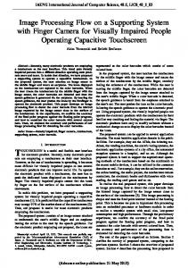
Speed Detection Camera System using Image Processing Techniques on Video Streams Osman Ibrahim, Hazem ElGendy, and Ahmed M. ElShafee, Member, IEEE
Abstract—This paper, presents a new Speed Detection Camera System (SDCS) that is applicable as a radar alternative. SDCS uses several image processing techniques on video stream in online -captured from single camera- or offline mode, which makes SDCS capable of calculating the speed of moving objects avoiding the traditional radars' problems. SDCS offers an en-expensive alternative to traditional radars with the same accuracy or even better. SDCS processes can be divided into four successive phases; first phase is Objects detection phase. Which uses a hybrid algorithm based on combining an adaptive background subtraction technique with a three-frame differencing algorithm which ratifies the major drawback of using only adaptive background subtraction? The second phase is Objects tracking, which consists of three successive operations, Object segmentation, Object labelling, and Object canter extraction. Objects tracking operation takes into consideration the different possible scenarios of the moving object like; Simple tracking, object has left the scene, object has entered the scene, object cross by another object, and object leaves and another one enters the scene. Third phase is speed calculation phase, which is calculated from the number of frames consumed by the object to pass-by the scene. The final phase is Capturing Object's Picture phase, which captures the image of objects that violate the speed limits. SDCS is implemented and tested in many experiments; it proved to have achieved a satisfactory performance. Index Terms—Image Processing, speed detection camera, radar, object recognition, object tracing.
I. INTRODUCTION The need to use radar systems is growing in importance. This is not only for military applications but also for civilian applications. The latter includes (but not limited to) monitoring speeds of vehicles on high ways, sport competitions, aeroplanes, etc [1-12]. The spread of use of radar systems is affected negatively with the high cost of radar systems and also with the increasing requirements on the accuracy of the outputs. This motivated the research on alternative technologies that offer both higher accuracy and be more cost effective. The field of image processing has grown considerably during the past decade. This has been driven by 1) the increased utilization of imagery in myriad applications, coupled with 2) improvements in the size, speed and cost
effectiveness of digital computers and related signal processing technologies. Image processing has found a significant role in scientific, industrial, space and government applications. Many systems nowadays can be replaced by image processing alternate systems that perform better than the former systems. An SDCS system is one of these systems that can replace traditional radars. An SDCS system is applicable as an alternative to current radar systems. This is better cost effective system than current ones. It also has accurate outputs as traditional radars or even better. SDCS system can be integrated with Automatic Number Plate Recognition (ANPR) system to form a complete radar system. ANPR system is a mass surveillance method that uses optical character recognition on images to read the license plates on vehicles. In the literal [1], authors introduce the primary steps towards developing the Speed Detection Radar. Here authors introduce a new approach in object detection technique, which is “adaptive background subtraction” as it proofs that it’s not sensitive to sudden illumination changes. Another feature is introduced here regarding object tracking by developing “object tracking categories”. Fully functional software is developed and captured windows are added in section IV. The rest of this paper is organized as follows. Section II presents the issues and system analysis of SDCS. Section III presents the novel design and theory of the system along with its implementation. Developed software snapshots are presented in Section IV. Section V concludes this paper. The system algorithms flowchart is presented in the Appendix. II. SSUES AND SYSTEM ANALYSIS This section discusses the problem definition, studying of traditional radar systems, then requirements and analysis of the proposed SDCS. A. Problem Definition Nowadays radars are extremely expensive. Nevertheless, their accuracy falls short of several potential applications. Consequently, they need to be replaced by automated system in order to have better accurate outputs, less expensive systems, and exclude human factor from the system. Recently there are two types of radars commonly used in Egypt: • High way radars: these radars are extremely expensive (about 200,000 – 300,000 LE). They calculate the speed of moving vehicles by means of sensors and capturing still image for vehicles violating limited speed. • Inner town radars: these radars are less expensive (about 70,000 LE). they calculate the speed of moving vehicles
Manuscript received May 4, 2011; revised August 5, 2011. Osman Ibrahim is with Informatique Corp, Cairo, Egypt, (e-mail:
[email protected]). Hazem ElGendy is with the Computer Science Dept., Ahram Canadian University, 6th October city, Giza, Egypt (e-mail:
[email protected]). Ahmed M. ElShafee is with the Network Dept., Ahram Canadian University, 6th October city, Giza, Egypt (e-mail:
[email protected]).
771
International Journal of Computer and Electrical Engineering, Vol. 3, No. 6, December 2011
• • • • • •
by means of sensors only and it needs an operator to capture the images for the vehicles violating speed limit. • Other technologies are being used to avoid detection by traditional radars; includes: • Laser detectors and radar detectors, which detect when the vehicle's speed is being monitored and warn the driver (these may be illegal in some areas). • Laser jammers and radar jammers, which "jam" the laser and radar by returning a scrambled signal which the speeding camera cannot process (these may be illegal in some areas). Thus, the need for another system to replace the traditional radars due to the disadvantages has become a necessity.
Specify the limited speed for objects. Specify the folder to save the images in. Detecting moving objects. Tracking moving objects. Shadow removal. Calculating speed of objects entered the scene and exit appropriately. • Marking the vehicle which violates the limited speed. The following are some of the system’s non functional requirements: • Interactive User Interface (GUI) • Troubleshooting for system inconsistencies • Portability • Performance Requirements(speed, response time) • Reliability of system with its functionality • Manageability and Ease of Use of the system main features • Scalability • Extensibility • Robustness
B. Systems Survey B.1 Gatso There are over 4,000 fixed Gatso speed cameras currently in use by police forces and local authorities across the UK [11]. The cost of installing a Gatso speed camera is approximately £20,000, but cost can go as high as £40,000 if located in a rural location, as the system requires a 240v power supply. The fixed Gatso camera has the ability to take up to 400 pictures. Gatso speed cameras can also distinguishes between cars/vans and HGVs separately. B.2 Truvelo [11] Truvelo system uses in the road, used to gain the vehicles speed and infrared flash light instead of visible flash light.. B.3 SPECS[11], [13] SPECS average speed camera systems utilize state of the art video system with Automatic Number Plate Reading (ANPR) digital technology. Consisting of a minimum of two cameras each fitted with infra red illuminators fitted on gantries above the road.
III. SYSTEM DESIGN, RESEARCH AND IMPLEMENTATION This section briefly discusses SDCS novel theory, system detailed design and project implementation. SDCS can be divided into four successive phases; these are • Objects detection • Objects tracking • Speed calculation • Capturing Object's Picture Detection of moving objects in video streams is known to be a significant, and difficult, research problem. Aside from the intrinsic usefulness of being able to segment video streams into moving and background components, detecting moving blobs provides a focus of attention for recognition, classification, and activity analysis, making these later processes more efficient since only “moving” pixels need be considered. The aim of object tracking is to establish a correspondence among objects or object parts in consecutive frames. It also aims to extracting temporal information about objects such as trajectory, posture, speed and direction. Tracking detected objects frame by frame, in video is a significant and difficult task. It is a crucial part of smart surveillance systems. This is because without object tracking, the system could not extract cohesive temporal information about objects. In such cases, higher level behaviour analysis steps would not be possible. On the other hand, inaccurate foreground object segmentation due to shadows, reflectance and occlusions makes tracking a difficult research problem. Since the output of object detection phase is considerably reliable and it handles sudden illumination changes and shadows. Therefore the foreground image is ready for segmentation, labelling and tracking. Also, the objects’ speeds can be calculated by detecting the first frame which the object has entered the scene at (Fr0) and keeping track of the object till it leaves the scene at frame (Frn). This is while neglecting the other unimportant objects such as people crossing the road.
B.4 Peek [11] Peek relies on radar technology, similar to a Gatso. They are also rear-facing due to the 'flash'. C. Primary Analysis After intensely analysis our problem domain and reviewing similar systems available nowadays, It was noticed that SPECS system is the nearest one to our system available nowadays. The main difference is that SDCS use only one digital camera and do analysis on videos in online or offline mode. The basic features that our system should include the ability to calculate the speed of moving objects avoiding the traditional radars’ problems. D. Requirements and Analysis Requirements may be either functional or non-functional requirements. Functional requirements specify the functionality that a system or component provide. • Supporting online and offline modes. • Categorization of inputted video in offline mode into predefined extension (avi). • Categorization of the camera to provide an online video stream in online mode. • Specify the distance captured.
A. Object Detection 772
International Journal of Computer and Electrical Engineering, Vol. 3, No. 6, December 2011
rate the difference between three successive frames will increase and if we use a high frame rate three frame differencing will act as two frame differencing with adding slightly more details.
A Hybrid algorithm for detecting moving objects [4] is used. It is based on combining an adaptive background subtraction technique with a three-frame differencing algorithm. This combination ratifies the major drawback of using only adaptive background subtraction. That is it makes no allowances for stationary objects in the scene that start to move. Although these are usually detected, they leave behind “holes” where the newly exposed background imagery differs from the known background model as shown in Figure 1.a While the background model eventually adapts to these “holes”, they generate false alarms for a short period of time. Frame differencing is not subject to this phenomenon; however, it is generally not an effective method for extracting the entire shape of a moving object as shown in figure 1.b.
Fig. 2. Motion matrix sample, a; sample scene with two moving objects, b; the constructed motion matrix represents the pixels which are in motion in the current frame ln.
(2)The masked subtraction Let Bn(x,y) be the corresponding background intensity value for pixel position (x,y) estimated over time from video images I0 through In-1. The foreground image F(x,y) can be formed by the formula:
F ( x, y ) =1 if | ln( x, y ) − Bn ( x, y ) | > Tn ( x, y ) 0 otherwise
This formula is being used by most of the background subtraction techniques. Our new formula is based on this formula and motion matrix which we discussed previously (sometimes referred to as the mask). This motion matrix can be used as a mask while subtracting the current frame In(x, y), the background Bn(x, y). The idea is that, if the pixel is not within the moving area, i.e. not in motion therefore we don’t need to apply background subtraction on it. In other words, if the pixel is not moving so we are going to neglect it since the probability of stationary pixel to be a part of an object is so low while the probability of another pixel which is in motion to be a part of object is so high. Ignoring other pixels will cause some loss of information, and will lead to un-connected objects. But, we combine the output of this operation with the result of the two frame temporal differencing (temporal differencing detect about 35-50% of the object). This is proven to give a very impressive result as shown in figure 2. So the foreground image F(x, y) can be formed by using our masked subtraction method, and the two frame differencing method.
Fig. 1.a. background subtraction leaves holes when stationary objects move. Fig. 1.b. frame differencing doesn’t detect entire object
To overcome these problems, we preferred to use the combination of the two methods. Object detection process, contains three different successive steps, these are (1)Constructing the motion matrix The main idea of this section is to construct a matrix corresponds to the current frame. This is being processed to decide what pixels are in motion and what are stationary. The moving pixels will have high probability to represent a foreground pixel while stationary pixels will have high probability to represent a background pixel. A three-frame differencing operation is performed to determine regions of legitimate motion as shown at figure 2 (we call that part “constructing the motion matrix”). It is followed by adaptive background subtraction to extract the entire moving region. Consider a video stream from a stationary (or stabilized) camera. Let In(x,y) represent the intensity value at pixel position (x,y), at time t=n. The three-frame differencing rule suggests that a pixel is legitimately moving if its intensity has changed significantly between both the current image (In) and the last frame (In-1), and the current image (In) and the next-to-last frame (In-2). That is, a pixel (x,y) is moving if
(| ln( x, y ) − ln −1 ( x, y ) |> Tn ( x, y )) and (| ln( x, y ) − ln −2 ( x, y ) |> Tn ( x, y ))
(2)
(1)
where Tn(x,y) is a Threshold describing a statistically significant intensity change at pixel position (x,y) (described below). The main problem with frame differencing is that at two frames differencing pixels interior to an object with uniform intensity aren’t included in the set of “moving” pixels [2]. Also, at three frame differencing is that its being high sensitive to noise. Nevertheless, if we use a low frame
Fig. (3). Masked subtraction sample, a: sample scene with moving object, b: foreground image constructed by masked subtraction, c: foreground image constructed using two frames differencing, d: final foreground image after combining both images
773
International Journal of Computer and Electrical Engineering, Vol. 3, No. 6, December 2011
Most of the foreground detection algorithms are susceptible to both shadows and sudden illumination changes which cause inaccurate foreground object segmentation. Since later processing steps like object classification and tracking depend on the correctness of object segmentation, it is very important to cope with shadow and sudden illumination changes in smart surveillance systems. After examining the properties of shadow one concludes that: 1. Shadow regions are darker. 2. Shadow regions represent the same background surface under a reduced illumination, and share similar textures to the background. There two approaches for shadow detection and removal, (1) using edge detection, (2) compare the intensities of pixel In(x,y), Bn(x,y). The drawback of the first approach simply is complexity, it is a time consuming approach but give an accurate results and can be used to differentiate between self shadow and cast shadow, but since our application main approach is speed while keeping quality in mind, we decided to use the second approach. Simply we need a robust and adaptive method to detect whether the current pixel In(x,y) is a foreground or shadow. After try and test we have concluded that: If 0.23 < In(x,y)/Bn(x,y)