May 21, 2013 - a supporting system to operate a capacitive touchscreen. In the proposed ... facilities. For example, they are the ATMs, the ticketing ma- chines ...
IAENG International Journal of Computer Science, 40:2, IJCS_40_2_03 ______________________________________________________________________________________
Image Processing Flow on a Supporting System with Finger Camera for Visually Impaired People Operating Capacitive Touchscreen Akira Yamawaki and Seiichi Serikawa
Abstract—Recently, many electronic products are employing a touchscreen as the user interface. This trend puts visually impaired persons into a difficult situation operating such products more and more. To tackle that situation, we have proposed a supporting system to operate a capacitive touchscreen. In the proposed system, the user attaches an image sensor to the middle finger and wears an earphone. The icons displayed on the touchscreen are replaced to the color barcodes. When the user traces the touchscreen by the middle finger with the image sensor, the color barcodes are detected and then the speech guidance is generated via the earphone. By hearing the speech guidance, the user pushes the icons by the forefinger to operate the electronic product. This paper develops an image processing flow to detect the color barcode from the blurred image captured by the image sensor close to the surface of the touchscreen. In the experiments, we confirm the accuracy of the fixed point program against the floating point program, and how to construct the color barcode with several colored bars. Then, we evaluate the accuracy and performance of our image processing flow for detecting the color barcodes. Index Terms—visually impaired, finger camera, touchscreen, supporintg system, color barcode.
I. I NTRODUCTION OUCHSCREEN is a useful and flexible user interface for electronic product. Recently, many electronic products are employing a touchscreen as their user interface. However, as the use of touchscreens is spreading, it becomes more difficult for visually impaired people to use several electronic products that can improve social life. To operate the electronic product with a touchscreen, the user has to push the dedicated icons displayed on the touchscreen by finger. The visually impaired people cannot feel the icons by finger on the flat surface of the touchscreen without unevenness. To tackle this problem, we have proposed a supporting system for visually impaired people operating a capacitive touchscreen [1]. It is predicted that the capacitive touchscreen may occupy 91% of the market share of the touchscreens [2]. Thus, our proposal is useful for most electronic products employing the touchscreen. The proposed system consists of an image sensor attached to underneath the user’s middle finger and an earphone issuing the action to the user by the speech guidance. For the electronic product employing our proposal, the icons are
T
Manuscript received April 19, 2013. This research was partially supported by the Telecommunications Advancement Foundation (TAF) of Japan. A. Yamawaki and S. Serikawa are with the Department of Electrical Engineering and Electronics, Kyushu Institute of Technology, 11, sensui, tobata, kitakyushu, fukuoka, 804-8550 JAPAN e-mail: {yama, serikawa}@ecs.kyutech.ac.jp.
represented as the color barcodes which consist of some colored bars. In the proposed system, the user touches the touchscreen by the middle finger with the image sensor and traces the surface of the touchscreen by the middle finger, certainly feeling the existence of the touchscreen. While the user is moving the middle finger, the color barcodes are detected from the images captured by the image sensor attached to the user’s middle finger. When a color barcode is detected, the speech guidance is heard from the earphone attached to the user’s ear. The user pushes the icon as the color barcode, following the speech guidance to operate the electronic product. Using proposed system, the visually impaired people can operate the electronic products with the touchscreen by their familiar way touching and feeling the material via finger. The electronic products have only to modify software without a mechanical change so as to display the color barcodes instead of the icons. The proposed system can be applied to several application domains. The most intuitive application domain is the public facilities. For example, they are the ATMs, the ticketing machines, the vending machines, the electric voting systems, the electronic application systems of a city office, the automated reception systems in a hospital, and so on. Although the proposed system is hard to support the sophisticated operating methods of the touchscreen based on the multitouch in the recent mobile devices, it can be utilized in the consumer domains as well. For example, they are the online reservation, the online banking, the audio players, the touchscreen remote controllers, the electronic books and dictionaries with voice reading, the trading card games and so on. To realize the real proposed system, this paper develops an image processing flow to detect the color barcode from the blurred image captured by the image sensor close to the surface of the touchscreen [3]. This image processing is simple and uses the fixed point number instead of the floating point. This is because we plan to implement this processing onto an embedded processor or hardware module in order to realize a wearable system with small size, low-power consumption and high performance. Through the preliminary experiment, we confirm the accuracy of the fixed point program against the floating point program, and how to construct the color barcode with several colored bars. Then, the accuracy and performance of the processing flow is evaluated for detecting the color barcodes. The rest of the paper is organized as follows. Section 2 clarifies the novelty of proposed system, comparing to the previous systems. Section 3 shows the overview of proposed system. Section 4 describes the processing flow proposed in
(Advance online publication: 21 May 2013)
IAENG International Journal of Computer Science, 40:2, IJCS_40_2_03 ______________________________________________________________________________________ this paper. Section 5 confirms the accuracy of the fixed point program against the floating point program, investigates how to organize the color barcode, and evaluates the accuracy and performance of the processing flow. Finally, Section 6 concludes our paper.
II. R ELATED W ORK Conventionally, several researchers have proposed supporting systems to help visually impaired people to operate the electronic products with a touchscreen. EdgeSonic [4] attempts to let the user imagine the shape of the image by the difference of sounds. A sound corresponding to the shape of the edge on the image is generated while the finger is tracing the touchscreen. Similarly, Timbremap [5] indicates the routes of finger, the button regions and the boundaries of the button regions by the difference of sounds. However, given only sound, it seems difficult that the user operates correctly the electronic product with the several icons and the hierarchy of screens. Some researchers have proposed to use the gestures of the finger instead of the icons [6], [7]. They map the finger gestures and the sequence of gestures with time duration to the operations of the electronic product. However, it seems difficult that the user memorizes all gestures with the time duration. The practice to correctly operate the electronic product by finger gestures must be required. The dedicated touchscreens instead of the traditional touchscreens have been proposed [8], [9]. The haptic display in [8] consists of many pins in an array fashion. According to the image to be displayed, the pins move up and down. Thus, the user can recognize the shape of image by finger tracing the touchscreen with unevenness. The haptic display in [9] use the electrobibration to indicate an unevenness of the touchscreen’s surface. These haptic displays show the feeling of touched part but cannot indicate the operations corresponding to the icons. Yamashita et al. have proposed a supporting system which consists of a stereo camera and an earphone in order to indicate kinds of icons and operations to the visually impaired user [10]. The stereo camera captures the finger and the touchscreen. The user moves the finger so as not to touch the touchscreen. The stereo camera traces the moving finger and measures the X-Y axis and the distance between the finger and touchscreen. Giving the speech guidance, the system indicates the kind of icons and shows the direction which has to move the finger. When the distance between the finger and touchscreen becomes zero, the system thinks the icon is pushed. This system need not modify a target electronic product in introducing the assisting feature. This merit is equal to ours. Also, this system is wearable as well as our proposed system. However, this system assumes that the stereo camera correctly captures the whole of the finger and touchscreen. It is difficult that the visually impaired people confirm this condition. Also, the user has to move the finger in the air without touching to the touchscreen. Thus, the user may feel uneasy about the operation of the electronic product.
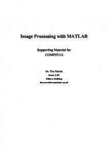
Fig. 1.
System Overview
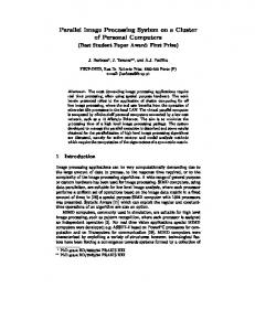
Fig. 2.
Examples of Captured Images by Image Sensor
III. P ROPOSED S YSTEM A. Overview Fig. 1 shows an overview of the proposed system. The user attaches the image sensor to the underneath of the middle finger and wears the controller to the back of the hand or the wrist. In addition, the user uses the earphone. The camera part consists of an image sensor and the start button. Some spacers may be equipped so that the image sensor does not directly touch to the touchscreen. The user moves the middle finger, pushing the camera part to the touchscreen. When the user touches the touchscreen by the middle finger, the start button is pushed. While the start button is pushed, the camera part captures the image and sends it to the controller. The controller recognizes the color barcode from the captured image sent by the camera part. According to the recognized result, the controller indicates the next action
(Advance online publication: 21 May 2013)
IAENG International Journal of Computer Science, 40:2, IJCS_40_2_03 ______________________________________________________________________________________
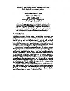
Fig. 3.
Button Organization
to the user by the speech guidance. The controller uses the database to decide next action and to trace the screen hierarchy according to the sequence of buttons the user has pushed. This database can be uploaded by any method, e.g. USB, WiFi, Bluetooth and UART, and so on. The speech guidance decided by the controller is sent to the speech guidance part. The speech guidance sent is represented by the sequence of the text data. Since the text data is small, the speech guidance can be sent via the wireless communication to avoid some obstacle caused by the wire connection for fitness. As shown in Fig. 1 (b), the touchscreen displays the color barcodes and button tags. The color barcode is within the button area which is margin for the forefinger pushing the button. The button area is not displayed on the touchscreen. The button tag can be used to indicate the meaning of the button to a non-handicapped person who supports the visually impaired user operating an electronic device. The supporting person can recognize the button by the button tag and can assist the user efficiently.
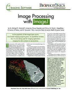
Fig. 4.
Image Processing Flow
meanings, for example literal, characters, the start point, and the end point. However, as shown in Fig. 2, since the blurred bars are fused, it will be difficult to represent some meanings by the differences of the width. Thus, we assume that the start point and the end point are represented by the back ground color like the black. Also, we assume that the width of the color barcode indicates only the number of bars. In addition, the colored bars in the captured image are mixed as shown in Fig. 2. Thus, the mixed color like yellow, magenta, cyan, and so on cannot be used for the colored bar. We assume that the colors of bar are red, green and blue. The number of buttons in a screen, N is expressed as Eq. 1.
B. Image Sensor To provide the smooth operational feeling, the distance between the middle finger and touchscreen has to be short as much as possible. Fig. 2 shows the examples of which a complementary metal oxide semiconductor (CMOS) image sensor module with different lens is put to the underneath of the middle finger. These pictures indicate that the long lens can capture the clear image but is not appropriate for providing the smooth touchscreen operation because the height of lens makes large distance between the middle finger and forefinger. Thus, we think that an image sensor with the short lens or non-lens is desired even if the captured image becomes blurred in the context of the natural operation. C. Barcode Organization As mentioned above, the captured image is blurred by using the image sensor with a short lens or without lens to reduce the gap between the middle finger and forefinger. The conventional 2D color barcode which consists of small cells may not be used. This is because the blurred image has not included the correct shape of each cell any longer. Thus, we assume that the color barcode consists of simple colored bars as same as the color code of the resistor, as shown in Fig. 3. In the conventional barcode that uses the black and white bars, the width of bar indicates several
N=
S∑ max
3i
(1)
i=1
Smax is the maximum number of slots. The hierarchy of multiple screens can express the buttons of N K at maximum. The K is the number of screens constructing the hierarchy. IV. I MAGE P ROCESSING F LOW Fig. 4 shows the image processing flow we have developed. The height of the captured image is limited to avoid the effect of the finger’s angle on the touchscreen. This image height is decided within the limit of which the accuracy of the barcode recognition is guaranteed. The captured image is blurred as shown in Fig. 2. The start and end points of the color barcode cannot be detected from such blurred image. Thus, a pixel whose value is lower than a threshold is set to zero at the phase shown in Fig. 4 (1). As a result, the start point and the end point of the color barcode would appear. After showing the start and end points of the color barcode, this flow tries to isolate the colored bars. However, since the colors of bars are mixed and the bars are fused, the red-green-blue (RGB) space is not suitable to isolate bars. Thus, the color space of the captured image is converted
(Advance online publication: 21 May 2013)
IAENG International Journal of Computer Science, 40:2, IJCS_40_2_03 ______________________________________________________________________________________ to the hue-saturation-value (HSV) color space at the phase shown in Fig. 4 (2). In the HSV space, the colors can be separated easily by using thresholds dividing the hue region, compared with the RGB space. In addition, the start point and the end point can be detected by using the saturation. This is because the start and end points are represented by the back ground color whose saturation is low. That is, the start and end points are within the invalid area where the colors of pixels lower than a saturation are erased. The button tags shown in Fig. 1(b) are drawn by a gray-scaled color with low saturation. So, the button tags are erased as well. Consequently, the RGB image is restored from the HSV image, by isolating colored bars of red, blue and green, according to the value of hue. In order to detect the existence of the color barcode and recognize the barcode, the histograms of the RGB and invalid colors are created from the restored image at the phase shown in Fig. 4 (3). Basically, the peaks of the histograms greater than thresholds are used to represent the colored bars. However, the noise at the boundaries between the colored bars and invalid area may happen like ringing. So, the filtering in Fig. 4 (4) eliminates such ringing and generates the smoothed wave forms. Finally, using the smoothed wave forms, the existence of the color barcode is detected by the histogram of the invalid color at the phase shown in Fig. 4 (5), and then the color barcode is recognized by the histograms of the RGB colors at the phase shown in Fig. 4 (6). Along the width direction, the colored bars are marked corresponding to the peaks continuously appearing. The start and end points that reside at the both edge of the image are marked similarly according to the width of the peaks. V. E XPERIMENT AND D ISCUSSION A. Experimental Setup Fig. 5 shows the overview of the experimental setup used in this experiment. We used the complementary metal oxide semiconductor (CMOS) image sensor, OV9655 of OmniVision. The resolution of the image sensor is 1280×1024 and its frame rate is 7.5 fps. The OV9655 outputs the pixel with 16 bit RGB. The G is 6bit. The R and B are 5bit. The OV9655 is connected to a field programmable gate array (FPGA) board, XUPV5 of Xilinx with the Virtex5 FPGA. The captured image is stored into the VRAM constructed of the embedded RAMs in the FPGA. The size of the captured image is limited to 1024×64 due to the limitation of the VRAM capacity. This experiment aims to perform a preliminary experiment for the color barcode recognition. So, the image processing shown in Fig. 4 processes the still image on the VRAM. The personal computer (PC) loads the stored image in the VRAM via UART and makes its bitmap file. This bitmap file is processed by the image processing developed. The color barcodes are displayed on the touchscreen of IPad2 of Apple. The width of the colored bar is 1 pixel. The number of colored bars is 3 since the OV9655 cannot capture the whole barcode with colored bars of 4 or more. B. Accuracy of Fixed Point Program We have designed the fixed point program of the proposed image processing flow shown in Fig. 4. In this flow, the main
Fig. 5.
Overview of Experimental Setup
Fig. 6.
Used Test Images
part of which the floating point is replaced with the fixed point is the color space conversion from RGB to HSV. We execute the fixed point version and floating point version of the color space conversion to the standard images, Lenna, Mandrill and Pepper shown in Fig. 6. The size of each image is 512 × 512. The size of a pixel is 24bit which consists of R, G, and B. The R, G and B are 8bit each. Then, the results of the fixed point and floating point programs are compared to confirm the accuracy of the fixed point program. Table I shows the experimental results. The MSE means mean square error between the fixed point program and the floating point program. The PSNR indicates the peak signalto-noise ratio between them. Table I indicates that our fixed point program has the same accuracy as that of the floating point one. TABLE I E XECUTION ACCURACY (F LOAT TO F IXED ) .
MSE PSNR
Lenna 0.32 56.0dB
(Advance online publication: 21 May 2013)
Mandrill 0.34 55.8dB
Papper 0.30 56.3dB
IAENG International Journal of Computer Science, 40:2, IJCS_40_2_03 ______________________________________________________________________________________ TABLE II R ESULT OF E VALUATION FOR C OLOR BARCODE O RGANIZATION .
Spacer with without
Number of barcodes Pass NG Total 31 8 39 16 23 39
C. Usable Barcode Since the number of colored bars is 3 in this experiment, the number of color barcodes is 39 according to Eq. 1. However, the degree of blurring and the performance of the used image sensor may practically limit the number of barcodes. So, we evaluate the recognition rate of 39 barcodes. Table II shows the experimental result. The spacer in Table II means the gap of 1 pixel between the colored bars. The result shows that the space can greatly improve the recognition rate. This is because the spacer separates colored bar more clearly. The false barcodes in this experimental setup are BGB, BRB, BRG, GBG, GRB, GRG, RBR, and RGR. This is because the middle bar or the side bars are disturbed by the other colored bar and disappeared. Henceforth, the spacers are inserted and the false barcodes are eliminated in this experiment.
Fig. 7.
Result of Performance Evaluation.
processing with the average filter and with the median filter mentioned in the previous section. Fig. 7 shows the result of the performance evaluation. The result shows that the case using the average filter outperforms that using the median filter by 3.23 times. This is because the median filter including sorting lengthens the execution time significantly, compared with the average filter. Consequently, we decide to use the median filter with the filtration degree of 32 to the images with the height of 8, for developing a prototype of the whole system shown in Fig. 1. VI. C ONCLUSION
D. Recognition Accuracy To reduce the processing time, lower height of the captured image is better. In contrast, the low height may lead to an inaccuracy for the recognition because the histogram with low height is weak to the impulsive noise. In addition, the filtering method to the histogram affects the recognition accuracy and the performance. To investigate the effects of them, this section evaluates the recognition rate, varying the image height, the filtering methods, and the filtration degrees. Table III shows the result of the recognition rate for 31 color barcodes selected in the previous section. Used filters are an average filter and a median filter. As a result, the median filter can achieve the perfect recognition rate in the lower image height compared with the average filter. However, the average filter outperforms the median filter in most filtration degrees of 8 to 16. This is because the large enough filtration degree extracted the performance of the average filter maximally. During the experiments, the finger rotation was within the natural angle in touching by the finger to the touchscreen. We have confirmed that the finger rotation to the color barcode does not affect the recognition result where the image height is lower than equal to 8. That is, without having to compensate the finger angle to the color barcode, the recognition can be performed correctly by setting the image height to 8 or below. As for the recognition rate of 100%, we think that the average filter with the height of 8 and the degree of 32, and the median filter with the height of 2 and the degree of 64 are candidates for the filtering. E. Performance Evaluation To optimize the performance of the proposed image processing flow, we have evaluated the performance of the image
We have proposed a supporting system for the visually impaired people operating a touchscreen. This system attaches the image sensor to the finger, recognizes the color barcodes as the icons by touching the touchscreen, and indicates the next action and the current situation by the audio speech. This paper has shown the image processing flow of the proposed system to recognize the color barcode from the blurred image that an image sensor close to the surface of the touchscreen captures. Through the preliminary experiments, we have confirmed that our fixed point program has the same accuracy as that of the floating point one. Also, we have investigated how to organize the color barcode, comparing two versions. The one has a space separating the colored bars and the other has no space. We have confirmed that the spacer of the background color inserted into the colored bars in the color barcode can increase the number of the usable color barcodes by improving the separation between colored bars. The evaluation of the recognition rate has been performed varying the image height, filtering methods and the filtration degrees. The used filters were a median filter and an average filter. The filterdation degrees were from 1 to 64. The result has indicated that a median filter with 32 degree is suitable to achieve the perfect recognition rate in this experiment using the images with height of 8 not suffering from the finger angle. In addition, the result of the performance evaluation indicates that the the average filter is better than the median filter in order to improve the performance. Consequently, we have decided to use the median filter with parameters mentioned above for progressing this research. As future work, we will develop the prototype of the whole system shown in Fig. 1. Then, we plan to perform the practical experiment by several testees.
(Advance online publication: 21 May 2013)
IAENG International Journal of Computer Science, 40:2, IJCS_40_2_03 ______________________________________________________________________________________ TABLE III R ESULT OF R ECOGINTION R ATE [%].
``` Filter `` Image height ````
None
1 2 4 8 16 32 64
15.1 30.9 33.3 57.8 86.2 94.7 100
Average Filter [degree] 8 48.6 87.1 80.2 92.4 98.9 99.6 100
16 66.9 96.6 92.6 97.9 99.5 100 100
32 78.0 92.6 99.5 100 100 100 100
64 74.6 85.1 96.4 100 100 100 100
Median Filter [degree] 8 48.2 73.2 74.0 88.5 98.4 99.6 100
16 71.7 90.6 88.4 96.2 99.1 100 100
R EFERENCES [1] A. Yamawaki and S. Serikawa, “A wearable supporting system for visually impaired people in operating capacitive touchscreen,” Applied Mechanics and Materials, vol. 103, pp. 687–694, 2011. [2] G. Walker, “Fundamentals of touch technologies and applications,” www.walkermobile.com/SID 2011 Short Course S4.pdf. [3] A. Yamawaki and S. Serikawa, “A color barcode detecting method in a supporting system for visually impaired persons operating capacitive touchscreen,” in Lecture Notes in Engineering and Computer Science: Proceedings of The International MultiConference of Engineers and Computer Scientists 2013, 13-15 March, Hong Kong, 2013, pp. 195– 199. [4] T. Yoshida, K. M. Kitani, H. Koike, S. Belongie, and K. Schlei, “Edgesonic: Image feature sonification for the visually impaired,” in Proc. of the 2nd Augmented Human International Conference, 2011, pp. 11:1–11:4. [5] J. Su, A. Rosenzweig, A. Goel, E. de Lara, and K. N. Truong, “Timbremap: Enabling the visually-impaired to use maps on touchenabled devices,” in Proc. of the 12th International Conference on Human Computer Interaction with Mobile Devices and Services, 2010, pp. 17–26. [6] S. K. Kane, J. P. Bigham, and J. O. Wobbrock, “Slide rule: Making mobile touch screens accessible to blind people using multi-touch interaction technique,” in Proc. of the ACM SIGACCESS Conference on Computers and Accessibility, 2008, pp. 73–78. [7] G. Yfantidis and G. Evreinov, “Adaptive blind interaction technique for touchscreens,” Universal Access in the Information Society, vol. 4, no. 4, pp. 328–337, 2006. [8] T. Handa, T. Sakai, M. Misono, T. Morita, and T. Ito, “Braille presentation method for tactile display,” in IEICE Technical Report, WIT2007-94, 2008, pp. 23–26 in japanese. [9] O. Bau, I. Poupyrev, A. Israr, and C. Harrison, “Teslatouch: Electrovibration for touch surfaces,” in Proc. of the 23nd ACM Symp. on User Interface Software and Technology, 2010, pp. 283–292. [10] A. Yamashita, S. Kuno, and T. Kaneko, “Assisting system of visually impaired in touch panel operation using stereo camera,” in Proceedings of the 2011 IEEE International Conference on Image Processing (ICIP2011), 2011, pp. 985–988.
(Advance online publication: 21 May 2013)
32 92.6 99.2 98.8 99.7 100 100 100
64 99.4 100 100 100 100 100 100