Bernardeschi C, Cassano L, Domenici A. SRAM-based FPGA systems for safety-critical applications: A survey on design standards and proposed methodologies. JOURNAL OF COMPUTER SCIENCE AND TECHNOLOGY 30(2): 373–390 Mar. 2015. DOI 10.1007/s11390-015-1530-5
SRAM-Based FPGA Systems for Safety-Critical Applications: A Survey on Design Standards and Proposed Methodologies Cinzia Bernardeschi 1 , Luca Cassano 2,∗ , Member, IEEE, and Andrea Domenici 1 1 2
Department of Information Engineering, University of Pisa, Pisa 56122, Italy Dipartimento di Elettronica, Informazione e Bioingegneria, Politecnico di Milano, Milano 20133, Italy
E-mail:
[email protected];
[email protected];
[email protected] Received December 21, 2013; revised October 10, 2014. Abstract As the ASIC design cost becomes affordable only for very large-scale productions, the FPGA technology is currently becoming the leading technology for those applications that require a small-scale production. FPGAs can be considered as a technology crossing between hardware and software. Only a small-number of standards for the design of safety-critical systems give guidelines and recommendations that take the peculiarities of the FPGA technology into consideration. The main contribution of this paper is an overview of the existing design standards that regulate the design and verification of FPGA-based systems in safety-critical application fields. Moreover, the paper proposes a survey of significant published research proposals and existing industrial guidelines about the topic, and collects and reports about some lessons learned from industrial and research projects involving the use of FPGA devices. Keywords
1
design verification, electronic design, safety-critical system, SRAM-based FPGA
Introduction
Since the first FPGA device was developed by Xilinx in 1984 with the XC2064 chip, the FPGA technology has enormously grown in terms of flexibility, reliability and computational power. Although it is still not comparable with ASIC technology in terms of either computational power or silicon area occupation, the FPGA technology has imposed itself in many application fields thanks to very good performance, low non-recurrent design cost and very short time to market. In particular, SRAM-based FPGA devices are employed in many application fields such as broadcast, wireless and wired communication systems[1] , cryptography and network security[2] , and consumer products, as well as in fields with stringent safety requirements, such as airborne[3] , aerospace and defense[4] , railways[5] , and industrial and nuclear power plant control[6] . This interest is due to the capability of SRAM-based FPGAs of being dynamically and partially reconfigured at run-time, which makes this technology much more
powerful and flexible than non-dynamically reconfigurable technologies, such as flash- and antifuse-based FPGAs. Using SRAM-based FPGAs and exploiting dynamic partial reconfiguration, a designer can adapt the functionality implemented by the system to changing environment and operational requirements. For example, dynamic partial reconfiguration has been used in a platform for satellite payload processing[7] . A satellite payload may perform different tasks in the course of its mission, such as acquiring data, processing it, and transmitting it to ground. FPGA devices may be reconfigured for each task, thus improving resource utilization. Nevertheless, SRAM-based FPGA devices are still seldom used in those parts of systems related with the safety of the system itself, due to the vulnerability to faults of the SRAM-based configuration memory[8] . On the other hand, in the last years, a number of dedicated conferences and workshops, such as the NASA/ESA Conferences on Adaptive Hardware and Systems and the Military and Aerospace Programmable Logic De-
Survey ∗ Corresponding Author ©2015 Springer Science + Business Media, LLC & Science Press, China
374
vices Workshops, demonstrate great interest in employing SRAM-based FPGA devices in safety- and missioncritical applications. In [9], the maturity of reconfigurable FPGA technologies for safety-critical applications is discussed. A safety-critical system is a system whose failure or malfunction may result in death or serious injury to people, loss or serious damage of equipment or environmental harm. In the IEC 615082 functional safety standard[10] , for safety related electric/electronic/programmable electronic systems (E/E/PE) operating in a low-demand mode of operation, the lower limit on the target failure measures is set at an average probability of 10−5 dangerous failures per hour of functioning. On the other hand, for E/E/PE safety-related systems operating in a high-demand continuous mode of operation, the lower limit is set at an average probability of 10−9 . As discussed in [11], testing alone cannot guarantee such requirement; combining fault tolerant approaches, such as replication and diversity, together with testing and other techniques such as Failure Mode and Effects Analysis (FMEA) and reliability analysis methods, can improve the reliability of the system, but the result is still far from the 10−9 goal. It is then necessary to complement the fault removal (i.e., testing) and fault tolerance strategies with a fault avoidance strategy, with the goal of producing high-quality systems, as free as possible of systematic faults. This goal can be achieved with rigorous development processes carried out according to standards that explicitly take into account the requirements of safety-critical systems. Many standards are available to developers of safety-critical systems, but most of them do not directly address the specific issues of the FPGA technology, or provide only limited guidance about them. There are two main differences between the ASIC and the FPGA design from the system designer point of view. The first difference is that the FPGA design flow is much more automated than the ASIC one, and thus it leads designers to rely much more on the CAD tools provided by the FPGA vendor and to pay less attention to verifying the correctness of the intermediate products of the various design phases and to trust too much the CAD tools[12] . The second difference is that the final product of the FPGA design is a software, i.e., the bitstream. Because of this, FPGAs are often perceived by designers as easy to modify and correct late in the development process, and thus FPGA-based systems are often designed with development methods more similar
J. Comput. Sci. & Technol., Mar. 2015, Vol.30, No.2
to a code and fix approach than a true hardware design process, and methods that would not be accepted for the design of more costly and less flexible technologies, such as ASICs or microprocessors[13] . In [13], Cercone et al. discussed how FPGA programming has not evolved much beyond the classical sequential development methodology of specifying requirements, creating the design, coding, simulating and testing. Often the documentation and testing of an FPGA project is left as an “end of project” task. The authors discussed how logic and functional testing is often completed only for known operational conditions, thus ensuring that the device does what it is supposed to do, but not ensuring that it does not perform unrequested functions. The paper strongly endorses the necessity of adapting verification and validation methodologies relying on modern design processes to the FPGA design, incorporating verification techniques as integral parts of the entire design process. Habinc[14] , as well as Fern´andez-Le´on[12] and Gibbons and Ames[15] , discussed how many problems and failures in space applications involving FPGA devices are the result of applying inadequate development, verification and validation methodologies. The authors observed that since the FPGA technology became sufficiently mature, it is being employed more and more heavily in space applications, performing more and more complex and critical tasks. Gibbons and Ames[15] discussed the failure of the NASA Wide Field Infrared Explorer (WIRE) project, which was due to the indeterminate state of the output of a control FPGA device, during the power-up phase. The authors focused on that experience, arguing that a robust design process of an FPGA-based safety-critical system must rely on a great experience of designers in any aspect of the specific FPGA technology employed. Finally, Fern´andez-Le´on[12] discussed the results of an audit of FPGA-based designs conducted by the European Space Agency, which revealed that the overall design methodology and the quality control applied to these designs were often poorly defined and in some cases even risky or negligent. Taking these issues into account, designers of FPGA-based systems often borrow the standards and guidelines from more traditional technologies and adapt them to the needs of FPGA-based development. Moreover, because of the lack of specific regulations and standards, a number of guidelines, such as [16], and lessons learned from research and industrial projects, such as [12-13, 15], have been published over the years.
Cinzia Bernardeschi et al.: SRAM-Based FPGA Systems for Safety-Critical Applications
Our work intends to present a brief overview of the existing standards for the use of FPGAs in safetyrelated systems, and, in general, hardware-based systems development, and to survey proposed techniques, guidelines and lessons learned about the design, verification and validation of FPGA-based safety-critical systems. This work is meant for both practitioners and researchers working in the field of design and verification of FPGA-based safety-critical systems. In particular, practitioners could exploit the present work to get a quick overview of the existing standards as well as to enrich their background through lessons learned from industrial and research projects involving the development of FPGA-based systems. On the other hand, researchers approaching the novel design and verification techniques could obtain from the present work a first picture of the existing trends. Since the design of an FPGA-based system has many steps in common with the ASIC design flow and since there is not yet a comprehensive and specific standard for the development of FPGA-based systems, in the following sections, we report general information, requirements and guidelines specific of ASIC designs but also applicable to FPGA designs, and, when available, activities and requirements specific of the FPGA design flow. The remainder of this paper is organized as follows: in Section 2, we briefly describe the main features of the FPGA technology; in Section 3, we quickly review the standards in force for FPGAs in safety-critical application fields; in Section 4, we present a survey of the research proposals, guidelines and lessons learned for FPGA-based system design and verification in safetycritical application fields; Section 5 presents the main techniques for the analysis of the effects of radiation on SRAM-based FPGA systems; Section 6 reports on some published case studies; Section 7 discusses open issues; finally, Section 8 concludes the paper. 2 2.1
FPGA Technology FPGA Programming
An FPGA is a prefabricated array of programmable blocks, interconnected by a programmable routing architecture and surrounded by programmable input/output blocks. Fig.1 shows the basic architecture of an FPGA chip. Programmable blocks may be simple combinatorial logic (soft logic blocks) or memories, multiplexers, ALUs and other kinds of prefabricated circuitry (hard
375
logic blocks). Logic blocks may be programmed to implement a certain functionality, the routing architecture may be programmed to interconnect various blocks, and I/O pads may be programmed to ensure off-chip connections.
Logic Block
Connection Box
Logic Block
Connection Box
Connection Box
Switch Box
Connection Box
Switch Box
Logic Block
Connection Box
Logic Block
Connection Box
Connection Box
Switch Box
Connection Box
Switch Box
Fig.1. Basic FPGA structure.
The purpose of the logic block is to provide the basic computational and storage element for the construction of the complete logic system. The programmable routing architecture, composed of wires and programmable switches, provides connections among logic blocks and I/O blocks to complete a user-designed circuit. Finally, the I/O architecture is composed of I/O pads disposed along the perimeter of the FPGA device, each one implementing one or more communication standards. FPGA programming consists of downloading to the device a programming code, called bitstream, that directly defines the hardware structure of the FPGA device by enabling or disabling gates in logic blocks to implement a certain function and of enabling or disabling connections between wires to connect or disconnect logic blocks, or to connect or disconnect logic blocks to/from I/O pads. Three FPGA programming technologies exist: static memory (SRAM) based, non-volatile memory (flash and EEPROM) based and antifuse-based[17] . In the static memory based programming technology, the bitstream is downloaded in the configuration memory of the device. This technology allows an indefinite number of device reprogrammings and has the best ratio of the device area for user resources to the area used by configuration memory, because static memory is realized with the same standard CMOS used for
376
FPGA devices. On the other hand, SRAM-based FPGAs need a supporting non-volatile memory to store the configuration data while the device is not powered. Further, FPGA devices based on SRAM are the most susceptible to the adverse effects of radiations. The flash/EEPROM programming technologies grant a limited number of reprogramming processes and have a worse real-estate utilization, because flash/EEPROM cells are fabricated with a nonstandard CMOS production process. On the other hand, these technologies do not need any supporting non-volatile memory. Further, flash/EEPROM-based FPGAs are much less susceptible to the effects of radiations, and, in particular, almost immune to single event upsets in the configuration memory. The antifuse programming technology does not allow any reprogramming of the device. Like flash/EEPROM-based FPGAs, also antifuse-based ones have bad real-estate utilization, but, again, they do not need any supporting non-volatile memory. Finally, antifuse-based FPGAs have no configuration memory, and are thus immune from long-term effects of SEUs (single event upsets). The FPGA device performance both in terms of computational speed and silicon area occupation is proportional to the size and complexity of the basic logic block, but the simpler the structure of the logic block itself, the higher the degree of flexibility and programmability offered to the designer, and thus a trade-off between performance and flexibility must be found. Likewise, the higher the number of switch boxes and long wires in the routing architecture and the number of communication standard implementable in a single I/O pad, the higher the flexibility level, but at the same time, the worse the computational speed and the area occupation performance. Modern FPGAs are extremely complex and powerful devices. They can be configured to host a complete microprocessor, or even a System-on-Chip, i.e., a complete system, composed of processor, memory and peripherals, all placed on the same chip. There are many embedded processors that can be placed on FPGA devices, among which we can mention the Xilinx MicroBlaze and PicoBlaze, and the Altera Nios and Nios II, provided by the FPGA vendors themselves. Further, apart from the previously mentioned soft-CPUs, more complex and powerful cores, such as the ARM CortexM1 core or the Gaisler LEON4 CPU, can be placed on modern, high-performance, FPGA devices.
J. Comput. Sci. & Technol., Mar. 2015, Vol.30, No.2
More detailed discussions about FPGA architectures can be found in [17]. 2.2
Advantages and Issues Related to FPGABased Designs
As has been analyzed in depth by Kuon and Rose[18] , FPGA-based designs are usually larger, slower and much more energy-consuming than full-custom designs. Nevertheless, they are more and more widely employed in all application fields and the interest in using FPGA devices in safety-related applications, such as space missions or railways systems, is growing. This is basically due to the two main factors of low cost and short time to market[17] . A full-custom design needs very expensive CAD tools for simulation, verification, synthesis, and floorplanning. Further, a full-custom design needs a large number of engineers working for many months. Finally, full-custom designs require the use of masks, which may cost several millions dollars, to drive the lithographic process. On the other hand, the cost of an FPGA device ranges between some tens and one thousand dollars. Further, licenses of CAD tools for FPGA-based designs are much cheaper than those of tools for full custom designs. The only large cost related to FPGA-based designs is the cost of the development team. Thus, especially for low-scale, and medium-scale productions, FPGAs are often the best technological choice. From the time to market point of view, after the completion of a full custom design process, the designing company must send the obtained masks to a silicon foundry (often located in a different country or even continent) to physically produce the chips, which may be sent back to the customer up to three months later. Then, the chips have to be tested and, if modifications to the design are needed, the design process has to iterate one of the previously performed design activities, after which a new fabrication process will be performed. A full custom design may need up to three fabrication iterations and thus up to twelve or even eighteen months between the product conception and its availability to customers. FPGA-based designs, instead, do not require fabrication delays. Design errors can be identified much more easily during the prototyping phase and thus the time to market of an FPGA-based design generally ranges between three and six months. The main issues related to the design of FPGAbased systems and their adoption in safety-critical application fields are the lack of standards specifically ad-
Cinzia Bernardeschi et al.: SRAM-Based FPGA Systems for Safety-Critical Applications
dressing the FPGA technology and the severe susceptibility of FPGA devices to the effects of radiations. As we have already discussed in the introduction of this paper, given the relative youth of the FPGA technology, and its not yet wide acceptance in safety-related application fields, there are very few design standards specifically addressing the FPGA technology. This, together with the ease and the low cost of prototyping and fixing defects, often led designers to underestimate design issues, thus causing projects failures. In order to overcome the lack of standards and to guide designers, several industrial guidelines and lessons learned from projects have been published. Radiations, both in space and at ground level, may cause a system to fail. In particular, radiations hitting the silicon surface of digital circuits may alter the content of memory elements. Radiation hitting SRAMbased FPGA devices may have even worse effects, since they could permanently corrupt the contents of the configuration memory (until a device reconfiguration), thus changing the functionality implemented in the device. 3
Standards Regulating the Design of Hardware Systems in Safety-Critical Systems
A general framework for the design and development of hardware and software safety-critical systems is the IEC 61508 standard, and in particular the IEC 61508-2[10] and the IEC 61508-3[19] for hardware and software systems respectively. Currently a specific regulation on FPGA design in safety-critical systems exists only in the aerospace application field: the ECSS-Q-ST60-02C[20] . Moreover, in the airborne application field, the RTCA/DO-254 standard[21] can be applied to the design and development of electronic systems and thus also to FPGA-based systems. In all the other application fields, the regulations in force require adopting the standard for the design and development of both software and hardware systems. In particular, in the automotive application field, the reference standards are the ISO/DIS 26262-5[22] and the ISO/DIS 26262-6[23] , and in the railways application field, the CENELEC EN 50128[24] and the CENELEC EN 50129[25] . Since the design of modern VLSI systems always involves the use of high level hardware description languages, all the standards agree on the application of a V-shaped design flow, which is inspired by the classical software design flow. Fig.2 shows the V-shaped design flow taken from the IEC 61508-2[10] standard for the
377
ASIC development lifecycle. Note that, although the figure representing the V-shaped lifecycle seems to be specifically related to ASIC designs, the same lifecycle has to be taken into account also when the design of an FPGA-based system is addressed[10] . In the V-shaped lifecycle, in each phase of the development (the left-hand branch of the V), requirements are defined and sub-products are produced to fulfill the requirements. Moreover, after each phase, the intermediate products of the phase are verified against the requirements specified in the previous phase: for example, the adequacy of the hardware architecture in fulfilling the requirements specification must be verified, the adequacy of the designed modules and their integration in fulfilling the architecture must be verified and so on. In the validation phase of the lifecycle (the righthand branch of the V), all the products of the development phase are evaluated in order to ensure correctness and consistency with respect to the global requirements. In other words, it must be verified that the obtained FPGA-based system fulfills the functional and safety requirements specified in the requirement specification phase and does not contain undesired functionalities. In some cases, this final validation shall be carried out by an independent party. The ECSS-Q-ST-60-02C standard requires that the system verification is performed in a realistic application environment. Thus, a system breadboard shall be designed and used by covering all the operating modes and conditions of the device. Also radiation testing shall be performed on the prototype if the required radiation-hardening level is not yet granted by the used technology. In the following of this section, we present a brief summary of the requirements imposed by the previously mentioned safety standards, and for each phase of the V-shaped design lifecycle, we place particular emphasis on the requirements imposed by the ECSS-Q-ST-6002C standard for FPGAs. 3.1
Development Process
3.1.1 System Safety Requirements Specification In this phase, starting from the requirements specification document of the whole system (named “E/E/EP system safety requirement specification” in the figure), requirements for the FPGA-based system are extracted and analyzed. In particular, it is recommended to identify those requirements that involve functionalities that
378
J. Comput. Sci. & Technol., Mar. 2015, Vol.30, No.2
E/E/PE System Safety Requirements Specification
E/E/PE System Architecture
ASIC Safety Requirements Specification
ASIC Validation
Validation Testing
Validated ASIC
Verification of Complete ASIC
ASIC Architecture
Module Integration Testing
ASIC Design and Behavioural Modelling
Module Testing
Module Design
Synthesis, Placement and Routing
Post-Layout Simulation
Output Final Coding
Verification
Fig.2. ASIC development lifecycle (the V-shaped model)[10] .
allow the system to reach and maintain a given safety level, those functions that allow the system to detect, identify and handle faults and those functions related to performance- and time-critical operations. The specification of the system requirements shall contain details relevant to the design to achieve the safety integrity level and the required target failure measure for the safety function, as specified by the E/E/PE system safety integrity requirements specification. In particular, the ECSS-Q-ST-60-02C standard imposes the following additional requirements related to the occurrence of faults due to radiation: • error handling, • test device on ground and flight, • proof of required fault coverage during tests. Moreover, the standard imposes the production of a feasibility study in order to estimate the requested power consumption, speed and radiation tolerance. At the end of this phase, a document that completely collects and defines the requirements for the FPGA-based system is produced. This document is required to be complete, unequivocal, clear and precise, verifiable and testable.
An interesting point is that all the standards highly recommend the use of semi-formal methods, such as logic/function block diagrams, sequence diagrams, data flow diagrams, and of formal methods, such as finite state machines, timed Petri nets, LOTOS, OBJ and Z, for the specification, the analysis, and the verification of high-level system requirements. 3.1.2 System Architecture In this phase, the overall architecture of the system is defined. In particular, the high-level components that will compose the system are identified, the interfaces among them are specified and the input and the output of the system are defined. Moreover, the decision on how to partition the system into its hardware and software components shall be taken during this design phase. A significant effort shall be paid in identifying a hardware architecture able to fulfill the previously defined safety requirements: for example, architectural-level fault-tolerance schemes are selected in this phase. Moreover, in this phase, it must be defined which components of the architecture will be developed from scratch and which ones will be purchased as the third party intellectual properties.
Cinzia Bernardeschi et al.: SRAM-Based FPGA Systems for Safety-Critical Applications
Desired qualities of the produced architecture are modularity, testability, maintainability, and low complexity. The produced architecture shall be verified according to the previously defined requirements. To ensure that the architectural design captures the information necessary to allow the subsequent development activities to be performed correctly and effectively, the architectural design shall be described with appropriate levels of abstraction by using semi-formal and formal notations. 3.1.3 System Design and Behavioral Modeling In this phase, the previously defined architecture is refined into a number of sub-components. The highlevel behavioral specification of these components is defined in this phase. All the standards agree on requiring the use of hardware description languages (behavioral VHDL/Verilog) to describe the behavior of the components and about the observance of coding guidelines. Furthermore, proven-in-use design environments and simulators shall be used. 3.1.4 Module Design During the module design, the high level behavioral model of the design is translated into a structural description composed of the hardware modules in accordance with the architectural design. In this phase, the use of behavioral/structural hardware description languages is highly recommended. Moreover, in this phase area, power consumption and timing constraints of the defined modules are specified. The ECSS-Q-ST-60-02C standard places particular emphasis on the definition of time constraints and of a detailed pin plan for FPGA designs. After each module has been designed, it must be tested in order to determine if it is fit for use. The purpose is to verify the implementation by testing every possible operational mode of the module. Static analysis tools are used to facilitate this process. After all modules have been designed and integrated in the complete system, integration testing shall be performed. In integration testing, the separate modules will be tested together to expose faults in the interfaces and in the interaction between integrated components. Testing is usually black-box as the code is not directly checked for errors. 3.1.5 Synthesis, Placement, and Routing After the detailed design has been completed, it must be synthesized so as to generate the gate-level
379
netlist implementing the system. During this phase, proven-in-use simulation, synthesis tools, and technological libraries must be used. In the placement and routing phase, the synthesized netlist is placed on the chip and routing information is defined in order to meet the timing constraints. Moreover, the power and clock distribution is performed. 3.1.6 Final Coding In the FPGA programming phase, the placed and routed design is translated into the programming bitstream, the FPGA device is programmed and the resulting prototype is tested. The design validation will be performed on the produced prototypes of the system. 3.2
Validation Process
After the development phase, the implemented design must be validated. The first validation step is the post-layout simulation. At this stage, 1) estimated delays shall be verified, 2) gate-level simulations, formal verification, and static timing analysis shall be performed, 3) key parameters such as voltages, noise, frequencies, bandwidth, power consumption, shall be verified, and 4) functional verification shall be performed. Moreover, the ECSS-Q-ST-60-02C standard asks to verify the effectiveness of the implemented radiationhardening mechanism. Finally, the standard places particular emphasis on the use of IP-cores: when such modules are purchased and used, great attention must be paid to the verification of the IP-core itself and to the verification of the correct integration of the IP-core into the architecture under design. In particular, it must be verified that the third-party IP-core exactly performs the functionalities declared by the vendor and does not implement hidden unwanted functionalities. Post placement and routing verification shall be performed: electrical properties and cross-talk sensitivity shall be evaluated; I/O timing and power distribution shall be checked; it must be verified whether the obtained post place-and-route netlist is functionally consistent with the gate-level netlist; timing performance shall be evaluated; clock skew and clock latency shall be estimated. Complete system testing will compare the system specifications against the actual system implementation. After the integration test is completed, the next test level is the system test. In the lower-level tests, testing is done against technical specifications, while system tests look at the system from the perspective of the customer and the future user. The testers
380
J. Comput. Sci. & Technol., Mar. 2015, Vol.30, No.2
validate whether the requirements are completely and appropriately met. Many functions and system characteristics result from the interaction of all system components, and consequently, they are only visible on the level of the entire system and can only be observed and tested there. 4
FPGA Research Proposals, Guidelines, and Lessons Learned
In this section, we propose a survey of research proposals, industrial and academic guidelines, and lessons learned from real-world projects regarding the design and verification of FPGA-based systems in safetycritical application fields. We have organized the survey following the structure of the V-shaped lifecycle previously presented. For each phase of the design process, we report activities that should be carried out as well as proposed techniques and tools. 4.1
Safety Requirements Specifications
In accordance to the standards, in [14] and [16], it is confirmed that the risk analysis should be carried out during the concept and requirements definition phase, along with the feasibility study and the requirements specification. According to these two studies, the feasibility study should: 1) analyze the availability and quality levels of the existing FPGA technologies and identify a set of candidate FPGA target devices taking into account the amount of available logic blocks and I/O pins, the maximum reachable operating frequency and the power consumption level; 2) conduct a preliminary worst-case timing analysis of external interfaces and clock domains; 3) check the availability and reliability of all required design tools and libraries. The requirements specification document should discuss the following aspects of the design: 1) identify details of the operating environment, such as temperature, humidity, and dust; 2) discuss safety-related requirements, such as self-test and auto-diagnostic capabilities, reliability, testability, maintainability, and observability requirements and radiation-hardening level; 3) identify requirements on the interfaces with external devices and the protocols that have to be followed between the device under design and any external devices; 4) determine the power budget and the operating frequency range of the system; 5) identify the timing, size, and electrical constraints of the system.
The risk analysis should identify the critical issues of the design and identify the possible backup solutions, including, but not limited to: 1) maturity of the foreseen FPGA device family, including CAD tools, libraries and vendor support; 2) suitability of the chosen technology for the intended mission; 3) undetermined I/O behavior and internal initial state during power-up. In [12], Fern´andez-Le´on stressed that a designer should implement a reliable development methodology for the definition, design, verification, physical implementation, and validation phases. Moreover, the author pointed out that designers should assess and document the radiation threats to the circuit. The effects of radiation on the circuit shall be identified, and countermeasures shall be properly designed, implemented and verified. In [26], an innovative FPGA requirements specification process for the design of safety-critical systems based on programmable devices is presented. It is suggested that the design process should start with a requirements specification redacted using the formal specification language Z. Then, using the INFORMED design method, the boundary between hardware and software components of the system is identified. Any basic computation is then partitioned, by deciding what shall be implemented in hardware and what shall be implemented in software. For those functionalities that shall be implemented in hardware, a manual refinement using Synchronous Receptive Process Theory (SRPT) is performed, and then each hardware module is compiled into Pebble, and subsequently in VHDL. Software components shall be implemented in SPARK Ada and they will interact using the Ravenscar tasking subset. The main Ada program, and the FPGA device will then communicate through a veneer component, sending data to and from the FPGA via a method appropriate to the particular system, such as shared memory or dedicated bus. Fig.3 shows the overall development process proposed in [26]. In [8], Sutton underlines the need of machinereadable formalisms for requirements specification in order to guarantee that all the requirements have been addressed during the design process. 4.2
System Architecture
At this stage of the design life-cycle, the target device shall be chosen and consequently the vendor’s CAD tool shall be chosen and purchased. The choice of older and more stable and reliable CAD tool instead of newer
Cinzia Bernardeschi et al.: SRAM-Based FPGA Systems for Safety-Critical Applications
ones, with better performance but lower reliability, is recommended. The use of hardware description languages, such as Verilog or VHDL, and of CAD tools to produce the architectural design is highly recommended. Specification (Z) INFORMED Boundary Design Partition
Ravenscar Processes
PLD Specification (Z) Refinement
SPARK Design Develop
SRPT Model
Proof
SPARK Code
CPU Target
Veneer
Compile PowerPC obj
Transform
ParSpark Compile
Pebble Compile VHDL
Fig.3. Development process proposed by Hilton et al.[26]
The guidelines proposed in [14] and [16] give also suggestions about the architectural design phase. In [14], Habinc gave recommendations about the architectural design phase of an FPGA employed in a safety-critical system. They were learned from the analysis of a great number of FPGA designs for space projects, many of which show problems related to the FPGA device itself. In particular, Habinc focused on four main issues: reset, clocks, power, and interfaces. While asynchronous reset allows an immediate reset of the flip-flop, it most often poses tight timing requirements on the routing of the reset signal. Because of this, the solution proposed in [14] is to assert the internal reset signal asynchronously and to de-assert it synchronously. For outputs that are critical for the system operation, it is recommended that the corresponding flip-flops are reset asynchronously. Finally, the state during and just after a reset should be documented in detail. Clocks should control all storage elements, i.e., the design should be fully synchronous. The number of
381
clock regions should be minimized since FPGA devices normally have only a few dedicated clock buffers. Since the choice between synchronous or asynchronous design is made at the HDL description phase, the use of simple HDL source code templates that are available from the FPGA vendors is highly recommended in order to avoid coding errors that would lead to an asynchronous architecture, while the desired architecture is synchronous, or vice versa. Clock gating techniques should be avoided. Concerning power consumption, Habinc[14] suggested avoiding clock signal manipulations that are in conflict with synchronous design methods. Careful attention to the power up and down sequences of FPGA devices should always be paid, since some technologies exhibit uncontrollable behaviors on their input and output pins during these phases. The power-up/power-onreset sequence should be carefully defined and documented, following the vendor guidelines. About I/O interfaces, Habinc suggested placing a Schmitt trigger inverter between the analog input sources and the FPGA inputs pins to reduce the risk of violating the rise and fall times. Moreover, Habinc recommended much attention in ensuring that bus contention cannot occur, internally as well as externally to the FPGA. FPGA devices have several special pins that are often not used by the application. Nevertheless, these pins need careful consideration during the design of the board on which the device will work. In general, it should be ensured that all special pins, test pins, and unused pins are properly terminated, strictly following the FPGA vendor guidelines. Unused pins should normally be left unconnected. It is not recommended to connect unused pins directly to power or ground. Finally, the state of the unused pins shall be properly documented. In [27], a large number of formalisms for high level architectural system modeling are presented, such as finite state machines, Petri nets and all their extensions, Statecharts and UML. Similarly, many languages and techniques for the verification of designed modules are discussed in [28]. The main approaches are: 1) the e language, an object-oriented language for testbench design, giving designers the chance to easily generate sets of input stimuli, specify constraints and properties, and assess the simulation coverage; 2) OpenVera, a testbench language similar to e, with a C-like syntax; 3) ForSpec, a temporal logic based specification and modeling language developed at Intel; and 4) Property Specification Language (PSL), originally developed in
382
J. Comput. Sci. & Technol., Mar. 2015, Vol.30, No.2
2004 by Accellera, and then standardized in 2005 by IEEE, which allows the designer to specify complex properties, combine them, and then verify the final properties. 4.3
Behavioral Modeling and Module Design
In this phase, a detailed description of the high level functional blocks defined in the previous phase shall be produced, implementing the defined functionalities, interfaces, interconnections, and interactions[14] . In this phase, the use of a hardware description language, such as Verilog or VHDL, and of CAD tools is also highly recommended. A strict coding standard should be used to avoid systematic faults due to coding errors: it is suggested to avoid non-synthesizable code and coding instructions that would lead to the insertion of latches. The use of constants and parameters is highly recommended. Naming, indenting, spacing, and commenting standards are useful to easily detect coding errors and to improve code understandability[16] . In [29], a VHDL guidance for safe and certifiable FPGA design is reported. Conmy et al.[31] recommended avoiding states with encodings that differ by just one bit when designing finite state machines: in this way, a single event upset could not cause the machine to jump into an unwanted state. Moreover, they strongly suggested limiting the size of each VHDL module in order to improve module testability and maintainability. Finally, they suggested careful attention to the development of operations involving floating point numbers since they are particularly difficult to manipulate on an FPGA. A very large number of alternative high level hardware programming languages have been proposed as intermediate languages between the architectural design and the description of the device structure in a hardware description language. Most of these languages are derived from C, such as Handel-C and SPARK, from C++, such as Streams-C and ASC, or from Java, such as Sea Cucumber. SystemC should be mentioned particularly, which is widely employed as a high-level design language for electronic systems. Alternative approaches are: ELLA, which allows abstraction and formal reasoning about the design; Esterel, a synchronous language used for programming reactive systems that can be automatically compiled in VHDL or Verilog; LAVA, a relational language designed to express circuit designs by describing the relative placement of building blocks of the circuit itself.
Finally the MATCH compiler and the AccelFPGA compiler allow translating MATLAB programs in VHDL and Verilog code for FPGAs. After the implementation of all HDL modules, the module integration phase shall be performed, gradually integrating the HDL modules in order to compose the whole system. Compliance to the required coding standards and guidelines must be verified[16] . Test benches shall be designed, in order to perform behavioral simulations of each module, to check both external interactions and interfaces and internal data flows. For complex designs, it is important to use self-checking test benches that can perform the test activity, automatically check the results, and produce a test report, without requiring a visual inspection of the waveforms. It is important at this phase to have automated test vector generators, in order to generate input sequences that can stimulate each part of the component at least once and as randomly as possible[16] . Also boundary value tests shall be performed in order to evaluate the robustness of the design. In [12], the necessity of inspecting and simulating the synthesized netlist in order to verify its correctness is emphasized. Moreover, SEU simulation and emulation are recommended. Finally, it is required to check whether the designed fault tolerance techniques have been properly implemented and synthesized, without any unwanted extra logic insertion or redundant logic resources removal by CAD tools. 4.4
Synthesis, Placement and Routing, and Final Coding
A number of studies presenting alternative placeand-route algorithms able to increase the robustness of a given design against faults have been published in the last years. In [30], the Reliability-Oriented Routing Algorithm (RoRA) for TMR-based designs is presented. The work starts from the consideration that the XTMR tool from Xilinx fails in some cases to protect the design from single event upsets due to the presence of common causes of failure in the routing of the design. RoRA heuristically places and routes the three replicas of the design and the voting circuit in such a way that the four components of the design do not share any routing resource. The algorithm proposed in [31] tries to keep the length of wires as short as possible in order to reduce the likelihood of open/short faults and to reduce the common regions between two nets in order to reduce the likelihood of bridge faults. In [32], an alternative cost function for an existing place-and-route
Cinzia Bernardeschi et al.: SRAM-Based FPGA Systems for Safety-Critical Applications
algorithm is presented. While legacy place-and-route algorithms try to optimize the timing or the area occupied by the design, the algorithm proposed in [32] tries to minimize the error propagation probability of the design. In [33], a place-and-route algorithm that aims at minimizing the number of configuration bits used by the routing resources of the design is presented. Finally, the problem of multiple cell upsets (MCUs) (bit flips of multiple configuration memory elements due to a single particle strike) in TMR-based designs is addressed in [34]. The paper presents PHAM, a placement algorithm that exploits the knowledge of the physical layout of the configuration memory of the device to maximize the distance between configuration memory cells belonging to different replicas of the design. After the synthesis, place-and-route and bitstream generation, the correct functionality of the system coded in the bitstream shall be verified, as discussed in [12, 16]. Moreover, the correctness and trustworthiness of externally purchased IP-cores shall be assessed. Nevertheless, verifying the correctness of a system at the bitstream level is an extremely hard task. FPGA vendors do not provide any detail about the structure of the bitstream, and the problem of verifying third-party IP-cores is made harder by the fact that very often these cores are provided as obfuscated or encrypted netlists. Thus, designers generally perform testing activities on the programmed device, spending great effort in designing sufficiently effective test cases. Nevertheless, testing cannot be exhaustive for medium/large scale designs. Recently, Luna Inc. has developed a software platform called Change Detection Platform (CDP)[37] . This environment is able to reconstruct the logic and postplace-and-route netlists, as well as the behavioral description of the system, starting from the bitstream. In this way, it is possible to verify that the translation tool provided by the FPGA vendor did not introduce bugs in the bitstream. Further, it is possible to verify whether the purchased netlist-level IP-cores do not contain defects, unwanted functionalities, or security flaws. 5
Radiation Effects Analysis and Mitigation
Radiations may produce system malfunctions[36] . In particular, radiations affecting digital circuits may cause changes in the contents of memory elements and in the value of signals. Radiations on SRAM-based FPGA devices have even worse effects, since when affecting the configuration memory, they could permanently change the functionality implemented in the device (until reconfiguration)[37] . The above mentioned
383
effect is known as single event upset (SEU). Other effects of radiations on digital circuits are the total ionizing dose (TID), i.e., the accumulation of charge in the interface between the metal and the oxide layers that cause an increase of power consumption and a decrease of circuit speed, and single event transients (SETs), i.e., transient impulses on wires in the circuit. Neither TID nor SETs have been widely studied in SRAM-based FPGAs since these devices are much more susceptible to SEUs, but they must be considered when other FPGA technologies are used[38-39] . Although the effects of radiation are much more intense in space, it has been demonstrated that radiation may corrupt the behavior of digital circuits also at ground level[40] . The ECSS-Q-ST-60-02C requires that the radiation hardening techniques implemented in the design are assessed through radiation testing and the SEU sensitivity of the system is analyzed. Moreover, techniques for mitigation of SEUs are either highly recommended or mandatory, depending on the safety level. A number of techniques have been proposed to this purposes. In the remainder of this section, we will first present the main techniques for the analysis of the effects of SEUs on SRAM-based FPGA systems, and then some SEU mitigation techniques. 5.1
SEU Effects Analysis Techniques
The sensitivity to SEUs of SRAM-based FPGA systems can be analyzed according to four main approaches: accelerated radiation ground testing, fault emulation boards, analytical computation, and fault simulation. Accelerated radiation ground testing[41] emulates the radioactive environment in which the system will work by exposing a prototype of the FPGA-based system to a flux of radiations. During the exposure to the radiation flux, the prototype is fed with a set of input patterns, and its behavior is monitored. The drawbacks of accelerated radiation testing are: 1) the impossibility of injecting SEUs only in the configuration memory of the FPGA, since the whole chip area will be irradiated (including user resources); 2) a possibility that the device be permanently damaged after the experiment; and 3) high cost. A number of fault emulation boards have been developed to evaluate the effects of SEUs in the configuration memory of SRAM-based FPGAs systems[42-43] . These boards emulate the occurrence of SEUs by modifying the bitstream of the target system whose behavior
384
is then dynamically evaluated. Fault emulation can be performed either before downloading the bitstream on the device under test, or at run time exploiting partial dynamic reconfiguration. Unlike radiation testing experiments, fault emulation allows focusing specifically on SEUs in the configuration memory of the FPGA, leaving out any other resources. Moreover, fault emulation avoids the risk of damaging the device under analysis. The drawbacks of SEU emulation are: 1) high cost; 2) complex usability; and 3) strong chip and vendor dependence. Analytical approaches, such as those presented in [44-46], have been developed to avoid the high cost of radiation testing and the long experimental time of fault emulation. In [44], a model based on the structure of the design implemented on the FPGA is built, and the topological modifications induced by SEUs in each configuration bit are deduced, thus discovering which SEUs affect the design. In [45], a model for the identification of sensitive paths to SEUs is presented. The model combines the error probability of all nodes of the circuit with the error propagation probability of each path of the circuit. Finally, in [46], a probabilistic model to estimate the reliability of SRAM-based FPGA system is presented. Given the probability of occurrence of an SEU, the model estimates the probability of having a system failure after a given amount of time. The drawback of these approaches is that, since the analysis is carried out without taking into account the input patterns fed into the system, they are able to provide a worst-case analysis while they are not able to provide information about the behavior of the system in its normal operating conditions. A large number of fault simulators for digital circuits can be found in the literature, but very few of them target the analysis of the effects of SEUs. Moreover, an even smaller number of simulators that specifically address the FPGA technology can be found. In [47-48], two simulators of SEUs affecting digital circuits have been proposed. Both simulators work at the gatelevel representation of the circuit, thus ensuring accurate results, but neither one takes into account any details specific of the FPGA technology. The only simulator targeting SEUs in FPGAs is SST[49] that works on the register transfer level representation of the system. Because of this, SST can only emulate the effects of SEUs in logic resources, e.g., flip-flops and memories, and it cannot reproduce the effects of SEUs in the configuration memory. Recently, a simulator of SEU effects in SRAM-based FPGAs, based on the stochas-
J. Comput. Sci. & Technol., Mar. 2015, Vol.30, No.2
tic activity networks formal specification language, has been proposed[50-51] . 5.2
SEU Mitigation and Correction Techniques
Many SEU mitigation techniques are discussed in the literature. In [52], SEU mitigation techniques are classified into two main families: fabrication process based and design-based. Fabrication process based techniques aim at reducing the effects of radiation through the use of nonstandard CMOS logic gates, such as the silicon-oninsulator (SOI) technology from IBM[53] and radiationhardened memory cells[54] . The approach proposed by IBM in [53] relies on the placement of a thin layer of silicon on top of an insulator during the manufacturing process. All the transistors of the device are then built on top of this silicon layer, which is characterized by a reduced capacitance, and then by a reduced susceptibility to the effects of radiations. Radiation-hardened memory cells rely on providing standard memory cells with feedbacks devoted to restore the correct value when the content of the cell is corrupted. These techniques are able to alleviate the long-term effects of radiation exposure (i.e., TID), and to reduce, but not to eliminate, SEUs. The main drawback of such solutions is the high cost due to the non-standard CMOS fabrication process. Design-based techniques rely on hardware redundancy, i.e., the use of extra components of the FPGA device (duplication or triplication) and voting systems to detect (when duplication is used) or correct (when triplication is used) the occurrence of SEUs[55] . A generalization of hardware redundancy is device redundancy, that is, using multiple independent FPGA devices performing the same functionality, whose output is then checked by a voting system. Designbased techniques are widely accepted because they are much cheaper than fabrication process based techniques. Hardware redundancy exploits the spare components (when available) of the FPGA device, and thus its cost (apart from the increased power consumption) is actually null. When device redundancy is used, the cost of multiple devices is always lower than the cost of non-standard CMOS devices. An additional advantage of design-based techniques is that they can be applied to different levels of design abstraction and can address different fault types. Finally, SEUs may be corrected by exploiting the partial dynamic reconfiguration capabilities of modern
Cinzia Bernardeschi et al.: SRAM-Based FPGA Systems for Safety-Critical Applications
FPGA devices through readback and reconfiguration[56] or memory scrubbing[57] . Both techniques are applied at run time, during the system normal operation. Readback and reconfiguration consist in periodically reading, either partially or totally, the contents of the configuration memory, comparing it to a golden copy of the bitstream and reconfiguring the device in order to correct any detected fault. Memory scrubbing is similar to memory readback and reconfiguration, and the main difference is that reconfiguration occurs at regular intervals. With blind scrubbing, the whole bitstream is reloaded, irrespective of the occurrence of faults, whereas with selective scrubbing, readback operations make it possible to identify faults and correct them with partial reconfigurations.
thus allowing the verification of safety properties in the presence of faults. The main safety property is that no more than one valve is closed at the same time, since this condition could block the hydraulic system. The property has been verified by model checking combined with FTA and FMEA under several fault hypotheses. The Esterel model has then been automatically translated into VHDL, leading to the FPGA implementation. The authors compare the automatic generation of VHDL code from Esterel with handwritten and optimized code, and conclude that the overhead of the automatically generated code is acceptable for the application, given the resource availability afforded by the FPGAs. 6.2
6
Reactor Trip System
Case Studies
In this section, we cite studies that report on FPGA applications in different industrial fields and address development issues. 6.1
385
Hydraulic Leakage Monitoring
Hydraulic systems are used in aircraft to actuate highly critical components, such as control surfaces and landing gear. Leakages may cause pressure losses, which may lead to catastrophic failures, and thus a hydraulic leakage monitoring (HLM) system is used to detect leakages and isolate defective sections of the hydraulic system by operating shut-off valves. Hammarberg and Nadjm-Tehrani[58] reported on the development of the electronic components of an HMS (white boxes in Fig.4), based on formal specifications written in the Esterel language. Esterel modules are used both for the system and the fault model,
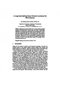
Andrashov et al.[59] described the development and V&V (verification and validation) process used for the control logic of reactor trip systems (RTS) implemented with FPGA technology. The RTS is the central and most critical part of a nuclear powerplant’s protection system. It samples sensor signals measuring physical magnitudes (e.g., temperature, pressure, or neutron flux), compares them with the allowed operating values, and shuts down the reactor if the prescribed limits are exceeded. Fig.5 shows the considered RTS, consisting of three signal channels feeding a two-out-of-three voter. The adopted development process is an adaptation of the V-lifecycle, where the development branch of the V is divided into two main phases, FPGA design and FPGA implementation. The design phase consists of the preliminary electronic design subphase, where the system is modeled at the diagram level and verifica-
Check Result
Sensors High Side Sensors Low Side
PLD 1
HS 1 Sensors
1B
1C HS 1 & HS 2
Value Sensors
H-ECU PLD 2
Shut-Off High Side
Value Blocks 2B
HS 2 Sensors Shut-Off Signals
Fig.4. Hydraulic monitoring system[58] .
Shut-Off Low Side
2C
386
J. Comput. Sci. & Technol., Mar. 2015, Vol.30, No.2
tion is done by design review, and the detailed electronic design subphase, where system is modeled at the schematics and VHDL level, and verification is done by simulation and static analysis. The implementation phase consists of the subphases of logic synthesis, placement and routing, and bitstream generation, where the system is modeled at the register transfer, netlist, and floorplan level, respectively. Verification is done by gate simulation and time simulation.
Operator's Control Panel of Main Control Room
Signal Forming Cabinet 1
Signal Forming Cabinet 2
Signal Forming Cabinet 3
2 out of 3 Cross Output Cabinet
considered BCU has been designed as a centralized FPGA controller replacing a number of electronic control units. The BCU includes a MicroBlaze processor, thus supporting the implementation of different functional parts of the application in software or in hardware. The adopted development process is centered on model-based design, for both hardware and software. The BCU functions are modeled with Simulink and Stateflow diagrams, from which HDL code (for hardware modules) and C code (for software) are automatically generated. The code is then synthesized for the Xilinx Spartan 3 FPGA. The authors reported data on resource requirement for different architectural approaches. An interesting result is that for some functional modules, a hardware implementation may require more FPGA resources than a software implementation using the MicroBlaze processor. 7
Open Issues
Output Control Signals
Fig.5. Reactor trip system[59] .
Special emphasis is placed on testing the RTS algorithms, i.e., the logic functions performed by the basic RTS subsystems. Thirty-four algorithms have been identified and tested by simulation with a 100% coverage of input value combinations chosen with the boundary value criterion. 6.3
Car Body Controller
Traub et al.[60] described the development of an FPGA-based body controller unit (BCU) (Fig.6), in charge of controlling a car’s electrically operated windows, rear-view mirrors, and other components. The
Many issues are still unsolved and make the application of SRAM-based FPGA devices in the safetyrelated parts of systems still problematic. Three main points remain open. The first is the lack of methods and tools for the formal verification of netlists at both the logic and the post-place-and-route level: what designers can do is just to simulate the obtained netlist trying to apply a sufficiently effective set of tests. This lack of methods has a twofold negative result: on the one hand, it is very difficult to verify the functional equivalence of the synthesized netlist with respect of the original high-level behavioral specification, which forces designers to trust the correctness of the synthesis process implemented by the vendor tool; on the other hand, it is unfeasible to verify the functional correctness and the absence of unwanted functionalities of the
LIN
CAN
Right Door
Rear Right
Power Window
Rear-View Seat Mirror Switch
Power Window
Power Window
Seat Rear-View Switch Mirror
Power Window
LIN Convertible Roof Control
Body Control
LIN
Roof
CAN
LIN
Left Door
Fig.6. Body controller unit[60] .
Rear Left
Cinzia Bernardeschi et al.: SRAM-Based FPGA Systems for Safety-Critical Applications
third-party IP-cores provided at the netlist-level, which forces designers to rely on the correctness of the purchased netlist. The second open point is the lack of open-source, freely modifiable and usable tools for the verification of the functional equivalence and the absence of unwanted functionalities of the obtained bitstream with respect of the previously verified netlist. For example, the Change Detection Platform of Luna Inc. is a highend tool developed in a research project of the US Defense Advanced Research Projects Agency, specifically addressed to the contractors of the US Department of Defense and not freely available. The lack of such tools, again, forces designers to rely on the correctness of the translation tool provided by the device vendor and on the trustworthiness of the IP-core provider. Finally, partial dynamic reconfiguration in safetycritical applications represents a still open point. Modern devices largely support partial dynamic reconfiguration. This allows the system to both activate a given functionality only when needed and deactivate functionalities when not needed (thus saving space), and to adapt its behavior to the changes in the working environment or in the user requirements[61] . On the other hand, the use of partial dynamic reconfiguration in safety-critical systems imposes hard requirements to the design, as discussed in [61]. In particular, the reliability of the data transfer is required if the new bitstreams are dynamically sent to the system when required, or a highly reliable persistent memory has to be used to store the unused bitstreams if the system is equipped with all the bitstreams since power-up. Furthermore, it must be ensured that the partial reconfiguration process does not affect the correct operation of the non-reconfigured part that may be required to keep working transparently. An additional open issue is related to the assessment of the sensitivity to SEUs. Radiation testing may entail too high a cost for small-scale designs and fault emulation takes a very long time for real-world designs. This gets even worse when a number of iterations of design and sensitivity analysis are required before achieving an acceptably robust design. To alleviate these problems early, assessment techniques have been proposed, in order to estimate the sensitivity of the system before implementing a prototype and thus allowing early corrections[44-46] . On the other hand, a number of techniques aiming at identifying the untestable faults in a design have been proposed[62-63] . The identification of those faults that can never be tested allows reducing the
387
number of faults that must be taken into account during the fault emulation process, thus speeding it up. On the other hand, what is still lacking is a unified framework of tools and techniques integrated in the standard design flow that may be used by designers at the various stages of the design. 8
Conclusions
This paper summarized the design standards for the development of FPGA-based systems in safety critical applications together with the literature proposals, industrial and academic guidelines, and lessons learned from real projects. Three main points about the design of FPGA-based systems in safety-critical application field can be identified. The first point is that it is strongly recommended to start the design of a safety-critical FPGA-based system only after a well-structured and well-documented design flow has been identified. The second recommendation is never to completely trust the CAD tools provided by the FPGA device vendor, and is always to verify the intermediate products of all phases of the design process using external tools (both simulation tools and formal methods). Finally, even if the design and development process of an FPGA-based system is very much like the design and development process of a software system, the designer must know in depth all the technological details of the final target device that will host the system, such as special I/O pins, working frequency range, temperature, voltage and humidity ranges. Tools and methodologies addressing these issues will boost the application of SRAM-based FPGA devices in safety-critical systems. References [1] Cardells-Tormo F, Valls-Coquillat J, Almenar-Terre V, Torres-Carot V. Efficient FPGA-based QPSK demodulation loops: Application to the DVB standard. In Proc. the 12th Int. Conf. Field-Programmable Logic and Applications, Sept. 2002, pp.102-111. [2] Mazzeo A, Romano L, Saggese G P, Mazzocca N. FPGAbased implementation of a serial RSA processor. In Proc. Conf. Design, Automation and Test in Europe, March 2003, pp.582-587. [3] Christophersen H B, Pickell W J, Koller A A, Kannan S K, Johnson E N. Small adaptive flight control systems for UAVs using FPGA/DSP technology. In Proc. the 3rd American Institute of Aeronautics and Astronautic (AIAA) Unmanned Unlimited Technical Conf., Workshop, and Exhibit, Sept. 2004, pp.1-8.
388 ´ V¨ [4] L´ edeczi A, olgyesi P, Mar´ oti M, Simon G, Balogh G, N´ adas A, Kusy B, D´ ora S, Pap G. Multiple simultaneous acoustic source localization in urban terrain. In Proc. the 4th Int. Symp. Information Processing in Sensor Networks, April 2005, Article No. 69. [5] Dobias R, Kubatova H. FPGA based design of the railway’s interlocking equipments. In Proc. the Digital System Design EUROMICRO Systems, Aug. 31–Sept. 3, 2004, pp.467-473. [6] She J, Jiang J. Application of FPGA to shutdown system No.1 in Candu. In Proc. the 6th American Nuclear Society Int. Topical Meeting on Nuclear Plant Instrumentation, Control, and Human-Machine Interface Technologies, April 2009, pp.1562-1573. [7] Sterpone L, Violante M. Analysis of the robustness of the TMR architecture in SRAM-based FPGAs. IEEE Transactions on Nuclear Science, 2005, 52(5): 1545-1549. [8] Sutton A. No room for error: Creating highly reliable, high-availability FPGA Designs, April 2012. http://www.synopsys.com / Solutions / IndustrySegmentSolutions/MilAero/Documents/FPGA-high-rel.pdf, Nov. 2014. [9] Sabena D, Sterpone L, Sch¨ olzel M, Koal T, Vierhaus H, Wong S, Glein R, Rittner F, Stender C, Porrmann M, Hagemeyer J. Reconfigurable high performance architectures: How much are they ready for safetycritical applications? In Proc. the 19th IEEE European Test Symp., May 2014. [10] International Electrotechnical Commission (IEC). 61508-2 ed2.0: Functional safety of electrical/electronic/programmable electronic safety-related systems — Part 2: Requirements for electrical/electronic/programmable electronic safety-related systems, April 2010. http://webstore.iec.ch/webstore/webstore.nsf/Artnum PK/43983, Nov. 2014. [11] Bowen J P, Stavridou V. Safety-critical systems, formal methods and standards. Software Engineering Journal, 1993, 8(4): 189-209. [12] Le´ on A F. Field programmable gate arrays in space. IEEE Instrumentation Measurement Magazine, 2003, 6(4): 4248. [13] Cercone J A, Beims M A, McGill K G. Verification and validation of programmable logic devices. In Proc. the 7th Military and Aerospace Programmable Logic Devices Int. Conf., September 2004. [14] Habinc S. Lessons learned from FPGA developments. Technical Report, FPGA-001-01, Gaisler Research, Sept. 2002. http://microelectronics.esa.int/asic/fpga 001 01-02.pdf, Nov. 2014.
J. Comput. Sci. & Technol., Mar. 2015, Vol.30, No.2 Report 578. http://www.nordtest.info/index.php/technical-reports/item/guideline-fordesign-and-safety-validationof-safetycritical-functions-rea lized-with-hardwaredescription-language-nt-tr-578.html, Nov. 2014. [17] Kuon I, Tessier R, Rose J. FPGA architecture: Survey and challenges. Foundations and Trends in Electronic Design Automation, 2008, 2(2): 135-253. [18] Kuon I, Rose J. Measuring the gap between FPGAs and ASICs. IEEE Transactions on Computer-Aided Design of Integrated Circuits and Systems, 2007, 26(2): 203-215. [19] International Electrotechnical Commission (IEC). 615083 ed2.0: Functional safety of electrical /electronic /programmable electronic safety-related systems — Part 3: Software requirements, April 2010. [20] European Cooperation for Space Standardization (ECSS). Q-ST-60-02C space product assurance: ASIC and FPGA development, July 2008. http://everyspec.com /ESA/ECSS-Q-ST-60-02C 48182/, Nov. 2014. [21] Radio Technical Commission for Aeronautics (RTCA). DO-254 design assurance guidance for airborne electronic hardware, April 2000. http://www.faa.gov/regulationspolicies/advisorycirculars/index.cfm/go/document.information/documentID/22211, Nov. 2014. [22] International Organization for Standardization (ISO). 26262-5: Road vehicles — Functional safety — Part 5: Product development at the hardware level, November 2011. https://global.ihs.com/doc detail.cfm?document name=ISO%2026262-5, Nov. 2014. [23] International Organization for Standardization (ISO). 26262-6: Road vehicles — Functional safety — Part 6: Product development at the software level, November 2011. https://global.ihs.com/doc detail.cfm?document name=ISO%2026262-6, Oct. 2014. [24] European Committee for Electrotechnical Standardization (CENELEC). EN 50128: Railway applications — Communications, signaling and processing systems — Software for railway control and protection systems, November 2011. [25] European Committee for Electrotechnical Standardization (CENELEC). EN 50129: Railway applications — Communications, signaling and processing systems — Safety related electronic systems for signaling, February 2003. [26] Hilton A J, Townson G, Hall J G. FPGAs in critical hardware/software systems. In Proc. the 11th ACM/SIGDA International Symposium on Field Programmable Gate Arrays, Feb. 2003, p.244 [27] Gomes L, Barros J P, Costa A. Modelling formalisms for embedded system. In Embedded Systems Handbook, Zurawski R (ed.), CRC Press, Boca Raton, FL, 2006, pp.134168.
[15] Gibbons W, Ames H. Use of FPGAs in critical space flight applications — A hard lesson. In Proc. the Military and Aerospace Applications of the Programmable Devices and Technologies Conf., 1999.
[28] Gupta S, Dutt N, Gupta R, Nicolau A. Spark: A highlevel synthesis framework for applying parallelizing compiler transformations. In Proc. the 16th Int. Conf. VLSI Design, Jan. 2003, pp.461-466.
[16] S¨ oderberg A, H´ erard J, Mortensen L B. Guideline for design and safety validation of safety-critical functions realized with hardware description language. Technical
[29] Conmy P, Pygott C, Bate I. A VHDL guidance for safe and certifiable FPGA design. In Proc. the 5th IET Conference on System Safety, October 2010, pp.1-6.
Cinzia Bernardeschi et al.: SRAM-Based FPGA Systems for Safety-Critical Applications [30] Sterpone L, Reorda M S, Violante M. RoRA: A reliabilityoriented place and route algorithm for SRAM-based FPGAs. In Proc. PhD Research in Microelectronics and Electronics, Vol.1, July 2005, pp.173-176. [31] Zarandi H R, Miremadi S G, Pradhan D K, Mathew J. SEUmitigation placement and routing algorithms and their impact in SRAM-based FPGAs. In Proc. the 8th Int. Symp. Quality Electronic Design, March 2007, pp.380-385. [32] Huang W, Meyer F, Park N, Lombardi F. Testing memory modules in SRAM-based configurable FPGAs. In Proc. Int. Workshop on Memory Technology, Design and Testing, Aug. 1997, pp.79-86.
389
over post synthesis netlist. In Proc. the 8th Military and Aerospace Programmable Logic Devices Int. Conf., September 2005. [44] Sterpone L, Violante M. A new analytical approach to estimate the effects of SEUs in TMR architectures implemented through SRAM-based FPGAs. IEEE Transactions on Nuclear Science, 2005, 52(6): 2217-2223. [45] Asadi G, Tahoori M B. An analytical approach for soft error rate estimation of SRAM-based FPGAs. In Proc. the 7th Military and Aerospace Programmable Logic Devices Int. Conf., Sept. 2004.
[33] Golshan S, Bozorgzadeh E. Single-event-upset (SEU) awareness in FPGA routing. In Proc. the 44th ACM/IEEE Design Automation Conf., June 2007, pp.330-333.
[46] Heron O, Arnaout T, Wunderlich H J. On the reliability evaluation of SRAM-based FPGA designs. In Proc. Int. Conf. Field Programmable Logic and Applications, August 2005, pp.403-408.
[34] Sterpone L, Battezzati N. A new placement algorithm for the mitigation of multiple cell upsets in SRAM-based FPGAs. In Proc. Conf. Design, Automation and Test in Europe, March 2010, pp.1231-1236.
[47] Schulz S, Beltrame G, Merodio-Codinachs D. Smart behavioral netlist simulation for SEU protection verification. In Proc. the 9th European Conf. Radiation and Its Effects on Components and Systems, September 2008, pp.406-411.
[35] Graf J. Change detection platform for FPGA trust. In Proc. Government Microcircuit Applications and Critical Technology Conf., March 2011.
[48] Calienes Bartra W, Reis R. SET and SEU simulation toolkit for LabVIEW. In Proc. the 12th European Conf. Radiation and Its Effects on Components and Systems, Sept. 2011, pp.829-836.
[36] Baumann R. Radiation-induced soft errors in advanced semiconductor technologies. IEEE Transactions on Device and Materials Reliability, 2005, 5(3): 305-316. [37] Graham P, Caffrey M, Zimmerman J, Sundararajan P, Johnson E, Patterson C. Consequences and categories of SRAM FPGA configuration SEUs. In Proc. the 6th Military and Aerospace Applications of Programmable Logic Devices, September 2003. [38] Wang J J, Cronquist B, McCollum J, Hawley F, Yu D, Chan R, Katz R, Kleyner I. Total dose and SEE of metalto-metal antifuse FPGA. In Proc. the 2nd Military and Aerospace Applications of Programmable Devices and Technologies Conf., September 1999. [39] Rezgui S, Wang J J, Sun Y, Cronquist B, McCollum J. Configuration and routing effects on the SET propagation in flash-based FPGAs. IEEE Transactions on Nuclear Science, 2008, 55(6): 3328-3335. [40] Normand E. Single event effects in avionics and on the ground. Int. Journ. High Speed Electronics and Systems, 2004, 14(2): 285-298. [41] Carmichael C, Fuller E, Fabula J, Lima F D. Proton testing of SEU mitigation methods for the Virtex FPGA. In Proc. Military and Aerospace Applications of Programmable Logic Devices, September 2001. [42] Alderighi M, Casini F, D’Angelo S, Pastore S, Sechi G, Weigand R. Evaluation of single event upset mitigation schemes for SRAM based FPGAs using the FLIPPER fault injection platform. In Proc. the 22nd IEEE Int. Symp. Defect and Fault-Tolerance in VLSI Systems, September 2007, pp.105-113. [43] Aguirre M, Tombs J N, Mu˜ noz F, Baena V, Torralba A J, Fern´ andez-Le´ on A, Tortosa-L´ opez F. FT-UNSHADES: A new system for SEU injection, analysis and diagnostics
[49] Guti´ errez D G. Single event upsets simulation tool functional description. Technical Report, TEC-EDM/ DGG-SST2, European Space Agency, 2004. http://microelectronics.esa.int/asic/SSTFunctionalDescription1-3.pdf, Nov. 2014. [50] Bernardeschi C, Cassano L, Domenici A, Sterpone L. Accurate simulation of SEUs in the configuration memory of SRAM-based FPGAs. In Proc. IEEE Int. Symp. Defect and Fault Tolerance in VLSI and Nanotechnology Systems, October 2012, pp.115-120. [51] Bernardeschi C, Cassano L, Domenici A, Sterpone L. ASSESS: A simulator of soft errors in the configuration memory of SRAM-based FPGAs. IEEE Transactions on Computer-Aided Design of Integrated Circuits and Systems, 2014, 33(9): 1342-1355. [52] Kastensmidt F L, Carro L, Reis R. Fault-Tolerance Techniques for SRAM-Based FPGAs. Secaucus, USA: SpringerVerlag New York, Inc., 2006. [53] IBM. SOI technology: IBM’s next advance in chip design, January 2000. http://wwwibm.com/chips/bluelogic/showcase/soi/soipaper.pdf, Oct. 2014. [54] Calin T, Nicolaidis M, Velazco R. Upset hardened memory design for submicron CMOS technology. IEEE Transactions on Nuclear Science, 1996, 43(6): 2874-2878. [55] Carmichael C, Fuller E, Blain P, Caffrey M. SEU mitigation techniques for Virtex FPGAs in space applications. In Proc. Military and Aerospace Programmable Logic Devices Int. Conf., September 1999. [56] Gokhale M, Graham P, Johnson E, Rollins N, Wirthlin M. Dynamic reconfiguration for management of radiationinduced faults in FPGAs. In Proc. the 18th Int. Parallel and Distributed Processing Symp., April 2004, pp.28-38.
390 [57] Heiner J, Collins N, Wirthlin M. Fault tolerant ICAP controller for high-reliable internal scrubbing. In Proc. IEEE Aerospace Conf., March 2008. [58] Hammarberg J, Nadjm-Tehrani S. Formal verification of fault tolerance in safetycritical reconfigurable modules. Int. J. Softw. Tools Technol. Transf., 2005, 7(3): 268-279. [59] Andrashov A, Kharchenko V, Sklyar V, Siora A, Reva L. Verification of FPGA-based NPP I&C systems: General approach and techniques. In Proc. the 19th Int. Conf. Nuclear Engineering in Osaka, October 2011. [60] Traub M, Sander O, Rathner A, Becker J. Generating hardware descriptions from automotive function models for an FPGA-based body controller: A case study. In Proc. MathWorks Automotive Conf., April 2008. http://www.mathworks.it/automotive/macde2008/proceedings/day2/ 04daimlergenertinghwdescriptionswithhdlcoderpaper.pdf, Oct. 2014. [61] Osterloh B, Michalik H, Habinc S, Fiethe B. Dynamic partial reconfiguration in space applications. In Proc. NASA/ESA Conf. Adaptive Hardware and Systems, July 29-August 1, 2009, pp.336-343. [62] Bernardeschi C, Cassano L, Domenici A. SEU-X: A SEU un-eXcitability prover for SRAM-FPGAs. In Proc. the 18th IEEE Int. On-Line Testing Symp., June 2012, pp.25-30. [63] Bernardeschi C, Cassano L, Domenici A, Sterpone L. Unexcitability analysis of SEUs affecting the routing structure of SRAM-based FPGAs. In Proc. the 23rd ACM Int. Conf. Great Lakes Symp. VLSI, May 2013, pp.7-12.
Cinzia Bernardeschi received her Laurea degree and Ph.D. degree in computer science in 1987 and 1996 respectively, both from the University of Pisa. She is an associate professor with the Department of Information Engineering of the University of Pisa. Her research interests are in the area of software engineering, dependable systems and application of formal methods for specification and verification of safety-critical systems. Her most recent work is related to the application of theorem proving and model checking techniques for fault simulation and reliability analysis of electronic circuits and systems.
J. Comput. Sci. & Technol., Mar. 2015, Vol.30, No.2
Luca Cassano received his B.S. and M.S. degrees both in computer engineering in 2006 and 2009 respectively from the University of Pisa, Italy. In 2013, he received his Ph.D. degree in information engineering from the Department of Information Engineering of the University of Pisa. During his Ph.D. course, Dr. Luca Cassano spent a visiting period at the Department of Automation and Informatics of the Politecnico di Torino, Italy, under the supervision of Dr. Luca Sterpone, and a visiting period at the Cognitive Interaction Technology — Center of Excellence (CITEC) of the University of Bielefeld, Germany, under the supervision of Prof. Mario Porrmann. Dr. Cassano is currently a postdoctoral research fellow at the Department of Elettronica, Informazione and Bioingegneria, Politecnico di Milano, under the supervision of Prof. Cristiana Bolchini. His research interests cover the analysis of the effects of SEUs in the configuration memory of SRAM-based FPGA systems, fault simulation, test and untestability analysis of digital circuits and systems, the use of machine learning techniques for fault testing and diagnosis for digital circuits and systems as well as the energy analysis of automatic weather stations.
Andrea Domenici obtained his Ph.D. degree in information engineering from the University of Pisa, Italy, in 1992. He has been an assistant professor at the Sant’Anna School of University Studies and Doctoral Research, Pisa, and is currently at the Department of Information Engineering of the University of Pisa, where he teaches software engineering and does research in the fields of dependable systems and application of formal methods in the development of safety- and mission-critical systems. He has also been active in object-oriented design and grid architectures. In this latter field, he took part in the European Datagrid Project and in the Enabling Grids for E-sciencE (EGEE) project, in cooperation with the European Organization for Nuclear Research (CERN) and the Italian National Institute of Nuclear Physics (INFN).