Journal of Multidisciplinary Engineering Science and Technology (JMEST) ISSN: 3159-0040 Vol. 1 Issue 5, December - 2014
STABILISATION OF HVDC TRANSMISSION SYSTEM USING PI CONTROLLER M. Ramesh Associate Professor &HOD,EEE, Dept Medak College of Engineering and Technlogy, Kondapak Medak Dist, Research Scholar, EEE Dept., JNTU, Anantapur-515002, Telangana, India Marpuramesh223@ gmail.com
Dr. A. Jaya Laxmi Professor, Dept. of EEE& Coordinator Centre for Energy Studies, Jawaharlal NehruTechnological University, College of Engineering, Kukatpally, Hyderabad-500085, Telangana, India
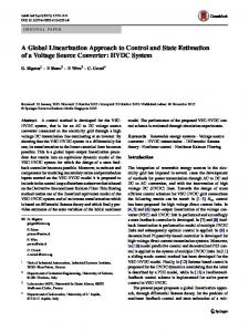
Abstract—The Stability of power systems is of predominate importance so as to take care of the integrity of power offer to the grid. There has been an incredible increase in power demand throughout the previous couple of years. Transmission of bulk power over long distances and interconnection of asynchronous AC systems is achieved using HVDC Transmission Systems considering economic factors, Technical performance and reliability. The inherent nonlinearity concerned in an HVDC link operation makes it trouble to design acceptable controllers under different normal and abnormal Situations. The performance of HVDC Transmission System and control of converters as an area of HVDC Transmission System is very important. The HVDC Transmission System is essentially controllable; thus, different kinds of control techniques are employed in order to possess effective and stable utilization and to extend the flexibleness of power Control. The HVDC Transmission System historically uses the PI controller to regulate the converter systems. This paper presents the CIGRÉ model united of the traditional strategies and new complementary characteristics are additional to boost its Stability and damping rate of Voltage and Current oscillations throughout the disturbance within the AC Systems and to extend the efficiency of the proposed model.
HVDC Transmission System and control of converters as an area of HVDC Transmission System is very important. The HVDC Transmission System is essentially controllable; thus, different kinds of control techniques are employed in order to possess effective and stable utilization and to extend the flexibleness of power Control. The HVDC Transmission System traditionally uses the PI controller to regulate the converter systems. This paper presents the CIGRÉ model united of the traditional strategies and new complementary characteristics are additional to boost its Stability and damping rate of Voltage and Current oscillations throughout the disturbance within the AC Systems and to extend the efficiency of the proposed model. From the start of Electric power history, HVDC Transmission lines and cables are more cost-effective and a lot of advantageous than AC Transmission. As power demand is increasing, so as to handle the majority power, one have to be compelled to utilize the savings that HVDC Transmission offers. Not only used for long distance power Transmission but in addition to enhance the Stability of the system [1-4]. Recently, as a result of advancement of power electronics Technology, High Voltage Direct Current (HVDC) Transmission Technology has been accustomed Enhance power System Stability. The HVDC is incredibly reliable, versatile and value effective [5, 6]. The HVDC technology that is predicated on thyristor valve has been developed since Nineteen Seventies. Principally as a result of price thought, the HVDC with thyristor valve is usually used for big point-to-point Transmissions, usually over long distances across land or under water. However, it exits commutation failure disadvantage, thyristors cannot be off instantly, and it in addition wants 40~60% reactive power provide of active power Transmitted. To beat the higher than shortcomings, IGBT switches are going to be used during this study. The benefits of IGBT over thyristor include [5, 6]. (i) IGBT Will turns out and on instantly (ii) there’s no commutation failure drawback (iii) no telecommunication is needed between 2 stations of VSC (Voltage supply Converter)-based HVDC system (iv) active and reactive power controlled severally (v) reactive power compensation is not needed, (vi) no restriction on multiple in-feeds, and etc. Thus, in this paper, the HVDC with IGBT switches that is termed HVDC are going to be projected and Analyzed to
Keywords—HVDC Transmission, CIGRÉ Benchmark model, Faults in HVDC System, Proportional Integral (PI) Controller. I.
INTRODUCTION
The Stability of power systems is of predominate importance therefore on pay attention of the integrity of power provide to the grid. There has been an amazing increase in power demand throughout the last few years. Transmission of bulk power over long distances and interconnection of asynchronous AC systems is achieved using HVDC Transmission Systems considering economic factors, Technical performance and reliability. The inherent non-linearity concerned in an HVDC link operation makes it trouble to design acceptable controllers under different normal and abnormal Situations. The performance of
[email protected]
www.jmest.org JMESTN42350228
188
Journal of Multidisciplinary Engineering Science and Technology (JMEST) ISSN: 3159-0040 Vol. 1 Issue 5, December - 2014
boost power grid stability. The control of associate HVDC Transmission system is greatly influenced by the AC/DC system strength. The AC/DC system strength is defined by the relative term "Short Circuit Ratio [SCR]"[7]. The SCR can be usually expressed as:
SCR =
Short Circuit MVA of AC System DC Converter MW Rating
An SCR value of 3 or higher than indicates the strong AC system, the SCRs of weak and very weak AC Systems range between 3 and 2 and below 2, respectively. The SCR is not a constant value because the AC System short circuit capacity and the ac system power change with operating conditions. Nonlinearities involved in the AC/DC systems can change the system operating point [8]. The standard fixed-gain Proportional Integral (PI) Controller within the HVDC Transmission System is optimized for a rated condition. a large vary of controller operation is not satisfactory for a fixed-gain controller. The standard controller suffers from longer recovery time and commutation failure once the HVDC Systems are connected to the weak DC Systems. CIGRÉ model has been introduced in 1991 [9]. This identified model is acceptable for the simulation of power systems [7]. In this model, the control strategy is predicated on the Voltage and Current coinciding Control and therefore the frequencies of two AC Systems are considered constant. Therefore, the frequency deviations don't play any role as a result of the disturbance occurs. In this paper, the CIGRÉ model is extended in such how that additionally to Voltage and Current, the frequencies of two AC systems (connected to every alternative by HVCD link) are considered as the parameters of the control system. In the proposed model, the frequency deviation is used (created during fault occurrence) as an additional control signal and the control system changes the DC Power so as to realize frequency stabilization and to enhance DC Current and DC Voltage waveforms. To achieve that goal, a benchmark system for HVDC Transmission System, referred to the CIGRÉ Benchmark Model, was proposed in 1985 [9, 10 and 11] and a benchmark system for HVDC Control study was additionally proposed II.PRINCIPLE OF HVDC CONTROL The power control is achieved by one among the subsequent three alternatives [12]. The diagram of an HVDC Transmission system is illustrated in Fig. 1
Fig.1 Schematic diagram of an HVDC Transmission System
(A). Constant Vd and Variable Id This technique has some disadvantages during short circuit on DC side. In this scenario, the Current Id increases sharply to high values. Also, the AC Voltage at AC systems varies with load Therefore to stay up constant DC Voltage, the tap-changer should be quickly controlled. However, this technique has benefits throughout low loads. During this condition, Id is small so RI2d loss result is low [12]. This technique is not widely used. (B). Constant Id and Variable Vd In this methodology Id is constant despite load. As a result, RI2d loss is constant and corresponds to rated Id. As Vd is variable .it will vary over a large vary, even the permissible limits of corresponding AC Voltages. A very large tap-changer may not permit such a large variation in Vd and Vac (AC bus bar Voltage) [12]. This methodology is not satisfied and is not employed in present HVDC Transmission Systems. (C). Hybrid Method of controlling Id by changing difference between Vd1 and Vd2 appropriately This methodology is employed within the fashionable HVDC Systems. In this method, both Vd and Id are controlled appropriately. This method provides practical solution to control problems and can improve the disadvantages of method (A) and (B) [12]. III. HVDC SYSTEM OPERATION MODE A two poles point-to-point HVDC System has been simulated under the environment of MATLAB.The operation mode of HVDC Transmission depends on the control mode of Rectifier and Inverter. In this study, we use Constant Current Control in Rectifier and Constant Extinction angle control in Inverter. The characteristic curve of Voltage Current Control is operated through the Constant Current control of a Rectifier and a constant extinction angle control of an Inverter in steady state, as show in Fig. 2.
www.jmest.org JMESTN42350228
189
Journal of Multidisciplinary Engineering Science and Technology (JMEST) ISSN: 3159-0040 Vol. 1 Issue 5, December - 2014
equivalent T network, which might be tuned to harmonic to produce a troublesome resonant condition for the modeled system (C) Converter
Fig. 2 Characteristic of the constant current control of the rectifier and a constant extinction angle control of inverter
In Fig. 2, QP and QU lines are the control characteristic of Rectifier side. QU is the result of Constant Current Control and belongs to Constant Current part; PQ represents the linear relation between Vdc (Direct Current Voltage) and Idc (Direct Current) when the Extinction angle keeps constant. RS and RT lines are the control characteristic of inverter side, and RT is constant part; RS is extinction angle part. [13] According to the above statement, it is easy to know that the operating point of this operation mode is nodal Z between QU and RS line. The Constant Current Control (QU) is that the Control that keeps this of SR line uniform. The firing angle alpha is adjusted with Current error, to take care of the SR Current Constant. Therefore, we have a tendency to use the firing angle (α) as a result of output of Rectifier Current Controller, whose inputs are Current error (e) and derivative error ( ∆ e). IV. CONVENTIONAL CIGRÉ HVDC BENCHMARK SYSTEM The conventional CIGRÉ HVDC benchmark system shown in Fig. 3 was planned in [12]. The system may be a monopolar 500 kV, 1000 MW HVDC link with twelve pulse converters on each Rectifier and Inverter sides, connected to weak AC Systems (short circuit ratio of 2.5 at a rated frequency of 50 Hz) that causes a substantial degree of problem for DC Controls. Filters and capacitive reactive compensation are also provided on either side. The power circuit of the convertor consists of the subsequent sub circuits: (A) AC Side
The convertor stations are drawn by 12-pulse configuration with 2 six pulse valves series. In the actual convertor, every valve is made with several thyristors serial each valve incorporates a di/dt limiting inductor and every thyristor has parallel RC snubbers. The control model principally consists of firing angle (α) and Angle Extinction (γ) measurements and generation of firing pulse for every Inverter and Rectifier. The used controllers in the control schemes as given below: • Extinction Angle Controller. • DC Current Controller. • Voltage Dependent (VDCOL) [14].
Current
Order
Limiter
(D) Rectifier control The rectifier control system uses Constant Current Control (CCC) Technique. The reference for Current limit is obtained from the Inverter side. This is done to make sure the protection of the converter in situations when Inverter side doesn't have sufficient DC Voltage support (due to a fault) or doesn't have sufficient load demand (load rejection). The reference Current employed in Rectifier control depends on the DC Voltage obtainable at the inverter side. DC Current on the Rectifier side is measured exploitation correct Transducers and therefore the obtained Current is responded to necessary filters before they're compared to supply the error signal. The error signals is then tried and true a PI controller that produces the required firing angle order [14]. It is desired to maintain the DC link Current constant by using a Current Controller at the Rectifier. This controller can perform its function by generating a control Voltage which then controls the firing pulses, at some delay alpha angle, to the rectifier valves. The relationship between DC Current Id and delay angle α is obtained as follows: The dc voltage at the rectifier is given by
= Vdr Vdor * cos α − X cr * I d ........................(1)
The AC sides of the HVDC System incorporates provide network, filters, and Transformers on each side of the convertor. The AC supply provides network is drawn by a Thevenin equivalent Voltage supply with equivalent supply impedance. Filters are added to absorb the harmonics generated by the converter additionally on provide reactive power to the convertor (B) DC Side
Where Vdr = DC line Voltage. Vdor=open circuit DC Voltage. And Xcr = equivalent impedance of converter transformer. For constant Id , and small changes in alpha, we have
The DC side of the device consists of smoothing reactors for each inverter and therefore the Rectifier side. The DC Transmission line is described by an
∆Vd = −Vdo *sin α ...............(2) ∆α
www.jmest.org JMESTN42350228
190
Journal of Multidisciplinary Engineering Science and Technology (JMEST) ISSN: 3159-0040 Vol. 1 Issue 5, December - 2014
The relationship between DC Current Id and alpha is given by
V *cos α − Vdoi *cos γ I d = dor ........................(3) Rcr + X cr − Xci
Where Vdor = open circuit Rectifier DC Voltage. Vdoi = open circuit Inverter DC Voltage. α = Rectifier firing (delay) angle. γ =Inverter extinction angle. Rdc= DC line resistance. Xcr= equivalent resistance of Rectifier, Xci= equivalent resistance of Inverter. Eq. (3) is only valid under steady-state conditions due to assumptions made in its derivation, and therefore the plant dynamics are not indicated. If the Inverter DC Voltage is maintained constant by controlling gamma (CEA control) then the DC Current is a function of Cos α i.e. a non-linear relationship. This implies that the loop gain will be lowest for a = 90 degs. resulting in nonoptimal dynamic properties for nominal values of α = 12 to 18 degs. Attempts to adapt the gain as a function of the operating angle have been used sparingly in the industry. This is partly due to the influence of other external parameters such as AC system strength and damping angle which are not considered in the above equations.
V. PI CONTROLLER The HVDC Transmission system historically uses the PI controller to regulate the converter systems. In a two terminal system, the Current margin rule is used, where the Rectifier is supplied with a Current Controller (CC) and also the Inverter side is supplied with a Constant Extinction Angle (CEA) Controller The Inverter system additionally incorporates a Current Controller in parallel with a CEA. An error signal, Ie that is that could be a distinction between the reference Current, Iref and measured Current, Id from the system is fed to the PI-Controller. The error output of the controller is acted upon by the PI gains to supply the desired alpha order for the HVDC Converter. The optimal gain calculation of the PI controller is difficult due to the fact that the HVDC Transmission system is uncertain and nonlinear. Consequently, combined field tests and simulation studies are conducted to fine tune these gains [15-16]. Fig.4 shows the structure of Proportional Integral (PI) Controller 1
Vmeas
1
U
K Ts 1
Vmeas
2
flag
forced_alpha
fault
z-1
GIE
fault
Product
U
GIE
t
pic
Clock fault
GU
dcfault
ec
GCE
dec
PI tunner
GCE delta_R Delta
K (z-1) Ts z
(E) Inverter Control
GCE
Discrete Derivative 3
Current_error
The Angle of Extinction Control or (γ) Control and Current Control are enforced on the Inverter side. The Constant Current Control (CCC) with Voltage Dependent Current Order Limiter (VDCOL) are used here through PI Controllers. The measured Current is then deducted from the reference limit to supply an error signal that's sent to the PI controller to supply the desired angle order. The Angle of Extinction Control (γ) uses another PI controller to supply gamma angle order for the Inverter. The two angle orders are compared, and the minimum of the two is used to calculate the firing instant. Fig. 3 shows Rectifier and Inverter control system [14].
-C-
error
Id_mar
e_R GU
GU
Fig.4 Structure of PI Controller
alpha_ord (deg)
PulsesY
Vabc (pu)
PulsesD
1
Pulses Vabc_R alpha_CC_R
Block
Freq
Max_Limit
12-pulse Firing Control
180 180
min
alpha_ord_R
MAX Forced Alpha
PI Control
In
Limiter
MIN
S1
Current_Error
Min_Limit
1
VdL_R
Max alpha
VdL_R a_ord_i Min alpha
Block
180
a_ord_v
180
a_ord_g
alpha_ord
mode
Mode_R
Protection and VDCOL Max_i
Min_i
Block
Control Mode
Fig. 5 HVDC system with PI Controller
VI. SIMULATION OF CIGRÉ HVDC SYSTEM MODEL The full three-phase model of the CIGRÉ HVDC benchmark system system is obtainable as associate degree example go into MATLAB Laboratory Data for the CIGRÉ HVDC benchmark system [9], [17]. Fig. 3 Single-line diagram of the CIGRÉ benchmark HVDC system
(A). Power Circuit Modeling
www.jmest.org JMESTN42350228
191
Journal of Multidisciplinary Engineering Science and Technology (JMEST) ISSN: 3159-0040 Vol. 1 Issue 5, December - 2014
(i) Converter Model: The converters (Rectifier and Inverter) are modeled using six-pulse Graetz bridge block, which incorporates an internal Phase Locked Oscillator (PLO), Firing and valve block controls, and Firing Angle α angle of extinction γ measurements. It also includes built-in RC snubber circuits for each thyristor. Thyristor valves are modeled as ideal devices, and therefore, negative turn-off and firing due to large dv/dt or di/dt are not considered.
smoothing reactors as shown in Fig 6. The converter Transformers devices (Wye grounded/Wye/Delta) area unit sculptured with Three-Phase Transformer (Three-Winding) blocks. The Transformer tap changers are not simulated. The tap position is rather at a fixed position determined by a multiplication factor applied to the primary nominal Voltage of the converter Transformers (1.01 on the Rectifier side, 0.989 on the Inverter side).
(ii) Converter Transformer Model: Two Transformers on the Rectifier side are modeled by three-phase two winding Transformer, one with grounded Wye–Wye connection and the other with grounded Wye–Delta connection. The models use saturation characteristic and tap setting arrangement. The Inverter side Transformers uses a similar model. (iii) DC Line Model: The DC line is modeled using an equivalent-T network with smoothing reactors inserted on both sides. (iv) Supply Voltage Source: The supply Voltages on both Rectifier and Inverter sides have been represented through three phase AC Voltage sources. (v) Filters and Reactive Support: Tuned filters and reactive support are provided at both the Rectifier and the Inverter AC sides, as shown in Fig. 3 (B). Control System Model The control model principally consists of α γ measurements and generation of firing signals for each the Rectifier and Inverter. The PLO is used to build the firing signals. The output signal of the PLO could be a ramp, synchronized to the phase-A commutating bus line-to-ground Voltage that is employed to come up with generates the firing signal for Valve 1. The ramps for other valves are generated by adding 60 to the Valve 1 ramp. As a result, an equidistant pulse is realized. The actual firing time is calculated by comparing the order to the value of the ramp and using interpolation [18] Technique. At the same time, if the valve is pulsed but its Voltage is still less than the forward Voltage drop, this model has logic to delay firing until the Voltage is exactly equal to the forward Voltage drop. The firing pulse is maintained across each valve for 120.The α and γ measurement circuits use zero-crossing information from commutating bus Voltages and valve switching times and then convert this time difference to an angle (using measured PLO frequency). Firing angle α (in seconds) is the time when valve turns on minus the zero crossing time for valve i. Extinction angle γ (in seconds) for valve i is the time at which the commutation bus Voltage for valve i crosses zero (negative to positive) minus the time valve i turns off. VII. SIMULATION RESULTS The Rectifier and therefore the Inverter area unit 12-pulse converters exploitation two Universal Bridge blocks connected in nonparallel. The converters are interconnected through a 850-km line and 0.597H
Fig.6 Simulink diagram of the HVDC Circuit
The HVDC Transmission link uses 12-pulse thyristor converters. Two sets of 6-pulse converters are required for the implementation stage. AC filters and DC filters are needed to attenuate harmonics. The firing-angle control system is organized supported two 6-pulse converters in series, one in all that is operated as a changed HVDC bridge. The HVDC power converters devices with thyristor valves are going to be assembled in an exceedingly converter bridge of 12 pulse configuration. This is accomplished by star-star affiliation and star-delta affiliation. Reduction of harmonic effects is another factor of investigation. Here, MATLAB/SIMULINK program is employed because the simulation tool two 6-pulse Graetz bridges are connected nonparallel to make a 12-pulse converter. The two 6-pulse bridges are 345Kv, 50 Hz totally identical except there is an in phase shift of 58.4° for the AC supply voltages. Some of the harmonic effects are cancelled out with the presence of 60° phase shift. The harmonic reduction can be done with the help of filters. The firing angles area unit forever maintained at nearly constant or as low as attainable so that the Voltage Control will be carried out. Six or eight of equal rating bridges are the best way to control the DC Voltage More Than these numbers of series bridges are not preferred attributable to the rise in harmonic content. The control of power can be achieved by two ways i.e., by controlling the Current or by controlling the Voltage It is crucial to take care of the Voltage within the DC link constant and only adjust the Current to reduce the power loss. The Rectifier station is liable for Current Control and Inverter station is employed to regulate the DC Voltage. Firing angle at Rectifier station and extinction angle of extinction at Inverter station area unit varied to look at the system
www.jmest.org JMESTN42350228
192
Journal of Multidisciplinary Engineering Science and Technology (JMEST) ISSN: 3159-0040 Vol. 1 Issue 5, December - 2014
performance and therefore the characteristics of the HVDC System. Both AC and DC filters act as large capacitors at fundamental frequency. The filters give reactive power compensation for the Rectifier consumption as a result of the firing angle. (A).Without Fault
Fig.9 shows the change process of the active power of HVDC System without fault with PI Controller. It is clear that for no fault, the PI controllers perform well and gives a better transient performance and quite a low overshoot. (B).With Faults
Fig. 10When DC fault occurs on rectifier
Fig. 7 Voltage and Current on the DC side at Rectifier
Fig. 11When DC fault occurs on Inverter
Fig. 8 Voltage and Current on the DC side at Inverter.
Fig.7 and Fig.8 shows the system with no fault in Voltage and Current waveforms at Rectifier and Inverter respectively, using the traditional PI controller. From the simulation results, it is observed that DC Voltage and Current reaches the reference value of 1.0Pu at 0.5 second, i.e. about 0.1 seconds later after starting HVDC System. When PI Control strategy is applied to the HVDC System, it reaches stable state after 0.55 sec.
Fig.10 and Fig.11 shows the Fault situated at the centre of the DC line at Rectifier and Inverter respectively. The fault starts at 0.6Sec and lasts for duration of 0.05s. The DC Voltage has gone all the way down to zero (the small oscillation is as a result of the energy stored in the capacitor), and a momentary transient DC Current has been determined. However, Control response forces Rectifier α and Inverter γ to reach maximum and Inverter α to reach minimum, thereby reducing the Current flow. VDCOL forces the Current to remain minimum till the DC Voltage scenario is improved. Once the fault is cleared, the DC Voltage is recovered, and therefore the control system brings the system back to traditional operation. It is seen that the developed HVDC Transmission System will recover the initial state when the DC fault is eliminated.
Fig. 9 Active powerat Rectifier
www.jmest.org JMESTN42350228
193
Journal of Multidisciplinary Engineering Science and Technology (JMEST) ISSN: 3159-0040 Vol. 1 Issue 5, December - 2014
PI Controller performs well but gives a better transient performance and quite a low overshoot.
Fig. 12 Active power when DC fault occurs
Fig.12 shows the change process of the active power of HVDC System after a DC fault is occurred with PI Controller. It is clear that for DC fault, the PI controllers perform well and gives a better transient performance and quite a low overshoot.
Fig. 13Voltage and Current waveforms when 20% change in load occurs on rectifier
Fig. 15 Active power when 20% change in load occurs
Fig.15 shows the change process of the active power of HVDC System when 20% change in load occurs with PI Controller. It is clear that for a 20% step change, PI Controllers perform well and gives a better transient performance and quite a low overshoot.
Fig. 16 When a line-to-ground fault occurs on Rectifier side
Fig.17 When a line-to-ground fault occurs on Inverter side Fig. 14 Voltage and Current 20%change in load occurs on Inverter
waveforms
when
A step modification of 20% is applied to the reference current and Voltage at Rectifier and Inverter side respectively. Fromthe simulated results (Fig. 13 and Fig. 14), it is clear that for a 20% step change, the
In Fig.16 and Fig.17, it is observed that a line-toground fault occurs on Rectifier and Inverter side of HVDC system respectively. The PI Controller activates and clears the fault. During fault, the DC Voltage has gone all the way down to zero (neglecting oscillation because of capacitor energy storage), the
www.jmest.org JMESTN42350228
194
Journal of Multidisciplinary Engineering Science and Technology (JMEST) ISSN: 3159-0040 Vol. 1 Issue 5, December - 2014
DC Current faces a momentary overshoot, and then goes to minimum limit with some oscillation present (due to the oscillation of DC Voltage).Rectifier α, inverter α, and inverter γ reach to maximum value, thereby blocking the system for the fault duration. Once the fault is cleared, at t=2 Sec. the system comes back to its normal operation.
Fig. 20 When a Three-phase fault occurs on Rectifier side
Fig.18 When a line-to-line fault occurs on Rectifier side
Fig. 21 When a Three-phase fault occurs on Inverter side
Fig. 19 When a line-to-line fault occurs on Inverter side
In Fig.17 and Fig.19, it is observed that a line-toline fault occurs on Rectifier and Inverter side of HVDC system respectively. The PI Controller activates and clears the fault. During fault, the Voltage has gone down to zero (neglecting oscillation due to capacitor energy storage) the Current faces a momentary overshoot, and then goes to minimum limit with some oscillation present (due to the oscillation of Voltage). Rectifier α, Inverter α, and inverter γ achieve to maximum value, thereby blocking the system for the fault period. Once the fault is cleared, at t=2 Sec. the system comes back to its traditional operation.
In Fig.20 and Fig.21, it is observed that a Threephase fault occurs on Rectifier and Inverter side of HVDC system respectively. The PI Controller activates and clears the fault. During fault, the DC Voltage has gone down to zero (neglecting oscillation due to capacitor energy storage) the DC Current faces a momentary overshoot, and then goes to minimum limit with some oscillation present (due to the oscillation of DC Voltage). Rectifier α, Inverter α, and inverter γ reach to maximum value, thereby blocking the system for the fault duration. Once the fault is cleared, at t=2 Sec the system comes back to its normal operation.
Fig. 22 Active powers when a line-to-ground fault occurs
www.jmest.org JMESTN42350228
195
Journal of Multidisciplinary Engineering Science and Technology (JMEST) ISSN: 3159-0040 Vol. 1 Issue 5, December - 2014
Fig.22 shows the change process of the active power of HVDC System after a line-to-ground fault is occurred with PI Controller. It is clear that for a line-toground fault, PI Controllers perform well and gives a better transient performance and quite a low overshoot.
contingencies in the power systems. Any oscillations observed after fault clearing are sufficiently damped. The Simulation results suggest that the stability of the system after a DC Transmission line fault is improved when longer HVDC Transmission lines are used. The constant gamma Control at the Inverter bus should be operated at the minimum extinction angle in order to enhance the power System Stability and reduce losses. Moreover, one potential good thing about the HVDC System is its capability to enhance the complete system dynamic Stability. As will been seen from Simulation results, the developed HVDC system will recover the initial state severally and obtained the Stability is good. Appendix 'A' Following are the parameters of the HVDC System chosen for the simulation studies: CIGRE HVDC Benchmark System Data
Fig.23 Active power when a line-to- line fault occurs
Fig.23 shows the change process of the active power of HVDC System after a line-to-line fault is occurred with PI Controller. It is clear that for a line-toline fault, PI Controllers perform well and gives a better transient performance and quite a low overshoot.
Parameters
Rectifier
Inverter
AC Voltage Base
345kv
230kv
Base MVA
100MVA
100MVA
Transformer tap(HV side)
1.01pu
0.989pu
Voltage source
1.088
∠22.180
0.935∠ − 23.140
Nominal DC Voltage
500kv
500kv
Nominal DC Current
2KA
2KA
REFERENCE [1] Guojie Li, T. T. Lie, G. B. Shrestha, and K. L. Lo, “Coordinated Optimal Control for Power System Enhancement”, Electric Machines and Power Systems, 27:1097-1112, 1999. Fig.24 Active power when a Three Phase fault occurs
Fig.24 shows the change process of the active power of HVDC System after a Three Phase fault is occurred with PI Controller. It is clear that for aThree Phase fault, PI Controllers perform well and gives a better transient performance and quite a low overshoot. VIII.CONCLUSION In this paper, the CIGRÉ model is developed for raising the performance of the System. For HVDC links where very large transient conditions are involved in the plant operation, it is more convenient to improve the PI Control Strategy rather than to work complicated dynamic models which require Sophisticated Control Strategies. In the paper, PI Control theme is planned a meant to enhance the performance of the HVDC Transmission System. The Simulation results presented in this paper show that the HVDC Control System will meet the required dynamic performance, even during severe
[2] G.J. Li, T. T. Lie, G. B. Shrestha, and K. L. Lo, “Implementation of Coordinated Multiple FACTS Controllers For Damping Oscillations”, International Journal of Electrical Power and Energy Systems, Vol. 22, pp. 79-92, 2000. [3] G.J. Li, T. T. Lie, C. B. Soh, and G.H. Yang, “Design and Implementation of a Class of Robust H∞ Control for Stability Enhancement in Power Systems”, Electric Machines and Power Systems, 28:839-860, 2000. [4] G.J. Li, T. T. Lie, C. B. Soh, and G.-H. Yang, “Decentralized Nonlinear H-Infinity Control for Stability Enhancement In Power Systems”, IEE ProceedingsGeneration, Transmission, and Distribution, Vol, 146, No. 1, pp. 19-24, January 1999. [5] Asplund. G., Eriksson. K, Svensson, K: “DC Transmission based on Voltage Source Converters”, CIGRE SC14 Colloquium on HVDC and FACTS in South Africa, 1997.
www.jmest.org JMESTN42350228
196
Journal of Multidisciplinary Engineering Science and Technology (JMEST) ISSN: 3159-0040 Vol. 1 Issue 5, December - 2014
[6] Asplund. G., Eriksson. K, Druggle. B, “Electric Power Transmission to Distant Loads by VSC HVDC”, Distribution 2000, Sydney, Australia, 1997. [7] K. Meah and A.H.M. SadrulUla, “Simulation study of the CIGRE HVDC benchmark model with the WSCC nine-bus power system network,” in: Proc. PSCE, pp. 1-5, 2009. [8] Jos Arrillaga, High Voltage Direct Current Transmission, 2nd Edition,PB LN MN MP MP LP The Institute of Electrical Engineers, Power and Energy Series 29, ISBN 0 85296 941 4, 1998. [9] M. Szechtman, T. Wess, and C.V. Thio, “A benchmark model for HVDC system studies,” in: Proc. International Conferene on AC and DC Power Transmision, pp. 374-378, 1991. [10] J. D. Ainsworth, “Proposed benchmark model for study of HVDC controls by simulator or digital computer,” in Proc. CIGRE SC-14 Colloq. HVDC With Weak AC Systems, Maidstone, U.K., Sep. 1985. [11] , “A benchmark model for HVDC system studies,” in Proc. Int. Conf. AC/DC Power Transmission, Sep. 17–20, 1991, pp. 374–378. [12] S. Rao, “EHV-AC, HVDC, transmission and distribution engineering,” KhannaPublilishers, Third Edition, 1999. [13] Zhou, Xiao-Xin, The Analysis and Control of AC/DC Power System, 2004. [14] M.O. Faruque, Yuyan Zhang, and V. Dinavahi, “Detailed modeling of CIGRÉ HVDC benchmark system using PSCAD/EMTDC and PSB/SIMULINK,” IEEE Trans. Power Del., Vol. 21, No. 1, pp. 378- 387, Jan. 2006. [15] V.K. Sood, N. Kandil, R.V. Patel, Khorasani, "Comparative evaluation of neural based and PI current controller for transmission," IEEE Transactions on Electronics, Vol. 9, No. 3, May 1994.
and K. network HVDC Power
[16] K.G. Narendra, V.K. Sood, K. Khorasani, R.V. Patel, "Investigation into artificial neural network based on-line current controller for an HVDC transmission link” IEEE Transactions on Power Systems, Vol. 12, No.4 November 1997. [17] “A benchmark model for HVDC system studies,” in Proc. Int. Conf. AC/DC Power Transmission, Sep. 17–20, 1991, pp. 374–378.
[18] G. D. Irwin, D. A. Woodford, and A. Gole, “Precision simulation of PWM controller,” in Proc. Int. Conf. Power System Transients, Rio de Janeiro, Brazil, 2001, pp. 301–306. Authors M Ramesh is working as a Associate Professor and HOD,EEE Dept, Medak College of Engineering and Technology, KondapakMeadkDist, and pursuing Ph.D. at JNT University, Anantapur.He is B.Tech in Electrical& Electronics Engineering and M.Tech in Advanced Power Systems, JNTU,Kakinada.He has many research publications in various international and national journals and conferences. His current research interests are in the areas of HVDC and Power System Dr. A. Jaya Laxmiwas born in Mahaboob Nagar District, Andhra Pradesh, on 07-11-1969. She completed her B.Tech. (EEE) from Osmania University College of Engineering, Hyderabad in 1991, M. Tech.(Power Systems) from REC Warangal, Andhra Pradesh in 1996 and completed Ph.D.(Power Quality) from Jawaharlal Nehru Technological University College of Engineering, Hyderabad in 2007. She has five years of Industrial experience and 13 years of teaching experience. She has worked as Visiting Faculty at Osmania University College of Engineering, Hyderabad and is presently working as Professor, JNTUH College of Engineering and Coordinator,Centre for Energy Studies,JNTUH, Kukatpally, Hyderabad. She has 40 International Journals to her credit. She has 100 International and National papers published in various conferences held at India and also abroad. Her research interests are Neural Networks, Power Systems & Power Quality. She was awarded “Best Technical Paper Award” for Electrical Engineering in Institution of Electrical Engineers in the year 2006. Dr. A. Jaya laxmi is a Member of IEEE and IAO, Life Member of System society of India, Fellow of Institution of Electrical Engineers Calcutta (M.I.E), Life Member of Indian Society of Technical Education (M.I.S.T.E), Life Member of Institute of Electronic &Telecommunication Engineers (MIETE),and Member of Indian Science Congress
www.jmest.org JMESTN42350228
197